
An Automated Approach of Test Case Generation for Concurrent
Systems from Requirements Descriptions
Edgar Sarmiento, Julio C. S. P. Leite, Noemi Rodriguez and Arndt von Staa
Department of Informatics, PUC-Rio, Rio de Janeiro, Brazil
Keywords: Requirements, Testing, Concurrency Testing, Scenario, Lexicon.
Abstract: Concurrent applications are frequently written, however, there are no systematic approaches for testing them
from requirements descriptions. Methods for sequential applications are inadequate to validate the reliability
of concurrent applications and they are expensive and time consuming. So, it is desired that test cases can be
automatically generated from requirements descriptions. This paper proposes an automated approach to
generate test cases for concurrent applications from requirements descriptions. The Scenario language is the
representation used for these descriptions. Scenario describes specific situations of the application through a
sequence of episodes, episodes execute tasks and some tasks can be executed concurrently; these
descriptions reference relevant words or phrases (shared resources), the lexicon of an application. In this
process, for each scenario a directed graph is derived, and this graph is represented as an UML activity
diagram. Because of multiple interactions among concurrent tasks, test scenario explosion becomes a major
problem. This explosion is controlled adopting the interaction sequences and exclusive paths strategies.
Demonstration of the feasibility of the proposed approach is based on two case studies.
1 INTRODUCTION
Initial requirements descriptions are appropriate
inputs to start the testing process, by reducing its
cost and increasing its effectiveness (Heumann,
2001; Heitmeyer, 2007; Denger and Medina, 2003).
UML models are widely used to specify
requirements; however test cases generated from
these models are usually described at high level, and
commonly it is necessary to refine them because
external inputs (conditions required to execute test
scenarios) are not explicit. And, most of them do not
deal with concurrency problems. In concurrent
applications, tasks interact with each other and
problems can arise from these interactions.
Although concurrent applications are frequently
written, there are no systematic approaches for
testing them. Methods for sequential applications are
inadequate to validate the reliability of concurrent
applications because of particular characteristics
such as interactions among tasks: synchronizations,
communications and waits (Katayama et al., 1999).
Due to multiple interactions among concurrent
tasks, it is difficult to derive and exercise all test
scenarios. Some path analysis methods (Shirole and
Kumar, 2012; Katayama et al., 1999; Sapna and
Hrushikesha, 2008; Yan et al., 2006) generate
sequential test paths and combine them to form
concurrent test scenarios. Because of irrelevant
combinations, test scenario explosion becomes a
major problem and besides, not all concurrent test
scenarios are feasible.
The execution of concurrent test scenarios makes
explicit potential problems raised by interactions
between tasks (Katayama et al., 1999; Sapna and
Hrushikesha, 2008). There is an interaction when 2
(or more) tasks T1 and T2 access or modify a shared
resource “v”, then, the execution order of T1 and T2
will impact the final result. If a test scenario is
executed with an expected output, test case passes. If
a test scenario is not executed or executed with
unexpected output, test case fails, and it could hide
interaction problems between tasks.
In this context, the Scenario language (Leite et
al., 2000) could be used to describe concurrent
applications through concurrent episodes; relevant
words or phrases of the application (Lexicon)
referenced into scenario: (1) make explicit input data
and conditions from initial requirements
descriptions, (2) represent shared resources accessed
or modified by concurrent tasks, (3) make explicit
the interactions by shared resources between
concurrent tasks. This information can be also used
339
Sarmiento E., C. S. P. Leite J., Rodriguez N. and von Staa A..
An Automated Approach of Test Case Generation for Concurrent Systems from Requirements Descriptions.
DOI: 10.5220/0004899703390347
In Proceedings of the 16th International Conference on Enterprise Information Systems (ICEIS-2014), pages 339-347
ISBN: 978-989-758-028-4
Copyright
c
2014 SCITEPRESS (Science and Technology Publications, Lda.)
to derive and reduce the number of test scenarios.
This paper proposes an automated approach to
generate test cases for concurrent applications from
requirements descriptions written on Scenario and
Lexicon languages. In this process, for each scenario
a directed graph is derived (represented as an UML
activity diagram). This diagram is used for the
generation of test scenarios using graph-search and
path-combination strategies, irrelevant test scenarios
are filtered adopting the interaction sequences and
exclusive paths strategies (See Section III).
The details of our proposal are presented in 6
Sections, from the description of the languages, the
strategy we propose and the case study, to the
related work and conclusions.
2 SCENARIO AND LEXICON
In this section we will describe the languages
proposed by Leite et al., (2000) and used in
requirement engineering to model requirements.
Language Extended Lexicon (LEL) is a language
designed to help the elicitation and representation of
the language used in the application. This model is
based on the idea that each application has a specific
language. Each symbol in the lexicon is identified by
a name or names (synonyms) and two descriptions:
Notion explains the literal meaning - what the
symbol is, Behavioral Response describes the effects
and consequences when the symbol is used or
referenced in the application. Symbols are classified
into four types: Subject, Object, Verb and State.
Table 1 shows the properties of a LEL symbol.
In (Gutiérez et al., 2006; Binder, 2000) and
(Sparx, 2011), relevant terms of the application are
described only by the name attribute as operational
variables and as project glossary terms.
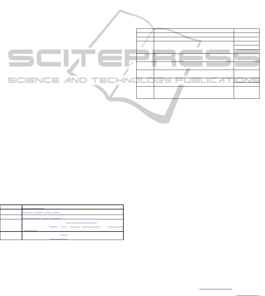
Table 1: Symbol definition in lexicon language.
Name
Symbol of LEL
Type
Subject/Object/ Verb/State
Synonymous
Term of LEL/Entry/Symbol
Notion
Word or relevant phrase of the Universe of Discourse.
It’s described by Name, Type, Notion, Synonymous and Behavioral
Response.
Behavioral
Response
Its description contains the Type.
It has zero or more Synonymous.
Scenario is a language used to help the
understanding of the requirements of the application,
it’s easy of understand by the developers and clients.
Scenarios represent a partial description of the
application behavior that occurs at a given moment
in a specific geographical context - a situation (Leite
et al., 2000; Letier et al., 2005).
There are different models of scenario (Leite et
al., 2000; Letier et al., 2005). In this work, the
scenario model is based on a semi-structured natural
language (Leite et al., 2000), and it is composed of
the entities described in Table 2.
Use case (Cockburn, 2001) is a particular model
of scenario; however, use case represents specific
situations between the user and the system through
interface. Scenario describes: situations in the
environment and the system; interactions among
objects or modules; procedures or methods. Table 2
explains how a scenario (Leite et al., 2000) can be
also used as a use case (Cockburn, 2001).
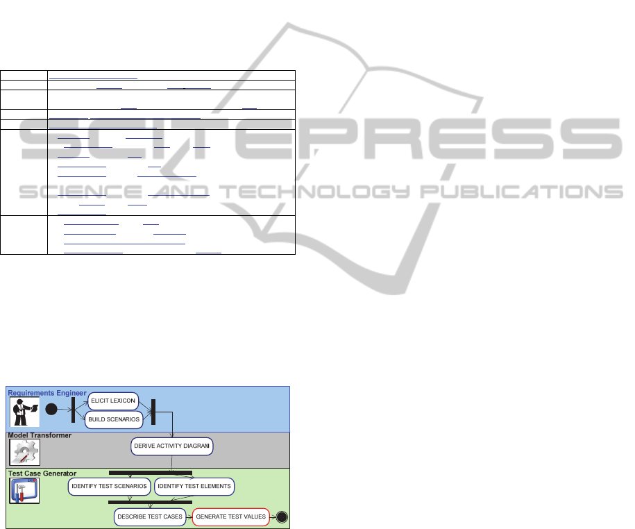
Table 2: Comparing scenario and use case.
Scenario Description Use Case
Title Identifies the scenario. Must be unique. Use Case #
Goal Describe the purpose of the scenario. Goal In Context
Context Describes the scenario initial state.
Must be descri
b
ed through at least one of these options:
precondition, geographical or temporal location.
Scope
Level
Preconditions
Resources Passive entities used by the scenario to achieve its goal.
Resources must appear in at least one of the episodes.
Trigger
Actors Active entities directly involved with the situation.
Actors must appear in at least one of the episodes.
Actors
Episodes Sequential sentences in chronological order with the
participation of actors and use of resources.
Description
Exception Situations that prevent the proper course of the scenario.
Its treatment should be described.
Extensions
Sub-Variations
Constraint Non-functional aspects that qualify/restrict the quality
with witch the goal is achieved. These aspects are
applied to the context, resources or episodes.
A scenario must satisfy a goal that is reached by
performing its episodes. Episodes represent the main
course of actions but they also include alternatives.
Episodes are: Simple episodes are those necessary to
complete the scenario; Conditional episodes are
those whose occurrence depends on a specified
condition (IF <Condition> THEN <Episode
Sentence>); Optional episodes are those that may or
may not take place depending on conditions that
cannot be detailed ([<Episode Sentence>])
A sequence of episodes implies a precedence
order, but a non-sequential order can be bounded by
the symbol “#”, it is used to describe parallel or
concurrent episodes (#<Episode Series>#).
While performing episodes, exceptions may
arise. They (Cause[(Solution)]) are any event arose
from an episode and treated by a Solution, it hinders
the execution of the episodes. An alternative flow
can be represented as a conditional episode (IF
THEN), or as an exception, where cause is the
condition and the solution is described as a simple
sentence or in other sub-scenario (alternative flow).
Scenarios are related to other scenarios by sub-
scenarios, which describes complex episodes,
solutions to exceptions, constraints, pre-conditions
and alternative flow of actions.
Lexicon symbols are referenced into scenario
descriptions; underlined UPPERCASE words or
phrases are other scenarios and underlined lowercase
ICEIS2014-16thInternationalConferenceonEnterpriseInformationSystems
340
words or phrases are lexicon symbols.
Table 3 describes a scenario of an ATM system
(Khandai et al., 2011). Here, an ATM machine
interacts with two other entities: The Customer and
the Bank. The customer starts the request by
inserting his/her card. The ATM must verify the card
and the personal identification number (PIN) to
proceed. If the verification fails the card is ejected.
Otherwise, the customer can perform some
operations and the card is retained in the machine
until the user finishes the transactions. Card
verification and PIN entering are done concurrently.
Table 3: Balance withdraw scenario of ATM system.
Title
BALANCE WITHDRAW
Goal
Withdraw the balance from a valid bank account.
Context
Geographical location: an ATM machine
Pre-conditions: The bank Customer must possess a bank card.
Resources
ATM Card, PIN, Account operation, Balance
Actors
Customer, ATM Machine, Bank.
Episodes
1. Customer inserts an ATM Card
2. # ATM machine verifies the Card in the Bank
3. Customer inserts the PIN. #
4. ATM machine verifies the PIN.
5. ATM machine displays customer account and prompts the customer to
choose a type of Transaction.
6. ATM machine verifies the Account operation.
7. verify balance in the Bank.
8. ATM machine display pick cash
Exceptions
2.1. Card is not valid (Eject Card).
4.1. PIN is not valid (Notify to Customer).
6.1. Account operation = Account affirm(Show account details).
7.1. Balance is not Ok (Display insufficient balance).
3 PROPOSED APPROACH
This section describes the activities for automation
of test case generation process from requirements
descriptions (Figure 1).
Figure 1: Workflow of our test case generation approach.
Requirements engineers start it by describing
requirements as scenarios and the relevant words or
phrases of the application as lexicon symbols (Leite
et al., 2000). Initially, scenarios are described using
natural language; these scenarios are transformed in
activity graphs. Graph paths are generated from
interactions among episodes, exceptions and
constraints of a scenario. This graph is used for the
generation of initial test scenarios using graph-
search and path-combination strategies. Scenario
descriptions reference lexicon symbols and they
represent the input variables, conditions and
expected results of test cases. The generation of test
values is not covered by this work.
State machine derivation from scenario
facilitates the validation of models because the
user/client can monitor the requirements execution
(Damas et al., 2005; Letier et al., 2005), and the
derivation of consistent test cases because
behavioral models increase the test coverage (Sparx,
2011; Katayama et al., 1999).
3.1 Building Lexicon and Scenarios
These tasks are carried out by requirements
engineers, which start to elicit and describe relevant
words or phrases of the application from different
information sources. Scenarios are DERIVED and
DESCRIBED from the lexicon of the application
(actors); after it, scenarios are VERIFIED,
VALIDATED and ORGANIZED. These tasks are
not strictly sequential due to feedback mechanism
present. There is a feedback when scenarios are
verified and validated with the users/clients and are
detected discrepancies, errors and omissions
(DEOs), returning to DESCRIBE task.
3.2 Deriving Activity Diagram
This sub-section describes the steps to transform a
scenario description in an activity diagram. Let AD
= {A,B,M,F,J,K,T,a
0
} be an activity diagram derived
from scenario C={Title, Goal, Context, Resources,
Actors, Episodes, Exceptions, Constraints}. AD
represents the visual behavior of C (AD ⇔ C).
Where A={a
1
,a
2
,...,a
i
} is a finite set of actions;
B={b
1
,b
2
,...,b
u
} a set of branches; M={m
1
,m
2
,...,m
v
} a
set of merges; F={f
1
,f
2
,...,f
y
} a set of forks;
J={j
1
,j
2
,...,j
x
} a set of joins; K={k
1
,k
2
,...,k
w
} a set of
final nodes; T={t
1
,t
2
,...,t
z
} a set of transitions which
satisfies
∀
t∈T, t=<c>e ˅ t=e where c∈C, e∈E,
C={c
1
,c
2
,...,c
l
} is a set of guard conditions,
E={e
1
,e
2
,...,e
s
} a set of edges of AD; and a
0
is the
unique initial state of AD.
According to (Sabharwal et al., 2011; Shirole
and Kumar, 2012), an activity diagram is a directed
graph G=(V,E) where V={A,B,M,F,J,K,a
0
} is a
union of vertices and E={T} is a set of transitions.
Figure 2 shows excerpt from the algorithm to
transform a scenario description in an activity
diagram. It starts by creating the initial node; it
creates decision nodes for constraints defined in
context and resources. For each episode of the main
AnAutomatedApproachofTestCaseGenerationforConcurrentSystemsfromRequirementsDescriptions
341
flow: it creates an action node (action described in
the episode), it creates decision nodes for
constraints, it creates decision nodes (causes) and
action node (solution) for exceptions, it creates
decision and merge nodes for conditional and
optional episodes, it creates fork-join structures for
concurrent episodes bounded by the symbol”#”.
Lexicon symbols (type: state) referenced into a
scenario will allow the creation of decision nodes
and transitions (and guard conditions) in the graph:
Conditions/options in conditional/optional episodes;
causes in exceptions and constraints in the context,
resources and episodes.
Input: A scenario C={Title,Goal,Context,Resources,Actors,Episodes,Exceptions,Constraints}
Output: An activity diagram AD={V,E} where V={A,B,M,F,J,K,a
0
} and E={T}
/*a
n
∈A; b
u
∈B; m
v
∈M; f
y
∈F; j
x
∈J; k
w
∈K; t
z
∈T; V={A,B,M,F,J,K,a
0
} and E={T}*/
1: Create the “initial state node” a
0
and the first transition t
z
∈T;
2: if constraints in Context is NOT empty then
Create a decision node b
u
∈B after a
0
, and transitions t
z ,
t
z+1
∈T;
3: if constraints in Resources is NOT empty then
Create a decision node b
u
∈B after previous node (b
u-1
or a
0
) , and transitions t
z ,
t
z+1
∈T;
4: for each episode ∈ Episodes do /*Iterate episodes*/
4.1: if episode starts with symbol “#” then Create a fork node f
y
∈F;
4.2: Create an action node a
n
∈A; whose name is the episode sentence;
4.3: if constraints in episode is NOT empty then
Create a decision node b
u
∈B after action a
n
, and transitions t
z ,
t
z+1
∈T;
4.4: if exceptions in episode is NOT empty then
for each exception ∈ exceptions in episode do /*Iterate episode’s exceptions*/
Create a decision node b
u
∈B after previous node, and transitions t
z ,
t
z+1
∈T;
4.5: if episode is CONDITIONAL then
Create a decision node b
u
∈B before previous action a
n,
and transitions t
z ,
t
z+1
∈T;
4.6: if episode is OPTIONAL then
Create a decision node b
u
∈B before previous node a
n
, and transitions t
z ,
t
z+1
∈T;
4.7: if episode is SIMPLE then Link nodes after and before action node a
n
∈A
4.8: if episode ends with symbol “#” then Create a join j
x
∈J and Link concurrent sub-paths;
5: Create the “final state node” k
w
∈K and the last transition t
z
∈T;
Figure 2: Deriving activity diagram from scenario.
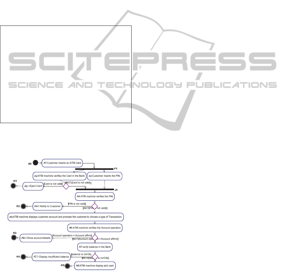
Figure 3 depicts the activity diagram derived from
scenario described in Table 3.
Figure 3: Activity Diag of ATM system balance withdraw.
3.3 Generating Test Cases
A test case is composed of a test scenario, input
variables or conditions exercise a test scenario and
verify that the result satisfies a specific goal.
3.3.1 Identifying Test Scenarios
If AD={V,E} is an activity diagram derived from a
scenario C, the different paths p
i
∈P between the
initial state and the final nodes of AD represent the
finite set of test scenarios, so, a test scenario (ts) is a
sequence of vertices and transitions of AD:
ts = path = p
i
= a
0
t
0
a
1
t
1
... a
n
t
n
k where:
a
i
∈
V \ K ˄ t
i
∈
E ˄ k
∈
V ∩ K, i=1,2,…,n.
For instance, p
2
is a test scenario of Figure 3:
p
2
:A
0
-A1-F1-A2<Not(Card is not valid)>J1-A4<PIN is not valid> A4.1-K2
A DFS (Depth-first search) algorithm can be used to
scan the finite set of sequential paths P on AD.
These paths execute sequential test scenarios;
however, for concurrent applications, the DFS must
generate a set of paths P, and for each p
i
∈P (p
i
contains concurrent action nodes) must generate one
or more finite set of concurrent sub-paths SP
i,j
,
where “i” is the number of path p
i
and “j” is the
number of fork-join structure on p
i
. A sub-path sp∈
SP
i,j
is a sequence of vertices and transitions of AD
between a fork “f” and a join “j” node:
sub-path = sp
=
t
x
a
y
t
z
where: a
y
∈
V \K ˄ t
x
, t
z
∈
E ˄ sp
⊆
p
i
For instance, in the Figure 3, SP
2,1
={sp
1
,sp
2
} is a set
of concurrent sub-paths (between F1: fork and J1:
Join) related to path p
2
, ⇒
sp
1
: - A2 - <Not(Card is not valid)>
sp
2
: - A6 -
Paths p
i
execute concurrent sub-paths sp as
sequential test scenarios (independent processes).
The combination of sub-paths sp
∈
SP
i,j
(between
same fork-join nodes) and the replacement of them
into p
i
can generate concurrent test scenarios
(Sabharwal et al., 2011; Katayama et al., 1999; Yan
et al., 2006). If N
sp
is the number of sub-paths of
SP
i,j
, then the number of combinations of size N
sp
is:
N
sp
!. The number of combinations could be reduced
when the interactions among sub-paths is specified.
There is an interaction when two (or more) sub-
paths sp
m
and sp
n
access or modify a shared resource
“v”. Interactions are: (1) Syncs denote a set of all
triplets of simultaneous execution of sp
m
and sp
n
in
SP (Synchronization), (2) Comms denote a set of all
triplets of communications from sp
m
to sp
n
in SP and
(3) Waits denote a set of all triplets where sp
m
waits
sp
n
in SP. So, the set of interactions is defined as
(Katayama et al., 1999):
Interactions(SP)= {Syncs(SP),Comms(SP),Waits(SP)}={(sp
m
, sp
n
, v)|sp
m
, sp
n
∈SP}
So, the proposed test scenarios derivation process
depends on the number of concurrent sub-paths,
ICEIS2014-16thInternationalConferenceonEnterpriseInformationSystems
342
which interacts each other (h). See Figure 5.
In concurrent applications described by
scenarios, lexicon symbols (type: object) can be
referenced by concurrent episodes. This Symbol(s)
is a shared resource “v” and usually, the value of “h”
is the number of concurrent episodes which
reference a shared resource “v”.
Let SP
i,j
be a set of sub-paths, N
sp
= the number
of sub-paths of SP
i,j
and GSP
i,j
the set generated of
the combination of the elements of SP
i,j
. Then, the
combination (variation) V(N
sp
,h) of elements of SP
i,j
will generate: |N
sp
|
h
combinations of size h.
If h is known, the number of combinations is
reduced from N
sp
! to N
sp
!/(N
sp
– h)! ⇒ |N
sp
|
h
≤ N
sp
!
If h = 1, then there are not interactions among
concurrent processes (parallelism). When we don’t
know the interactions among processes: h = N
sp
.
For instance, in the Figure 3 SP
2,1
={sp
1
,sp
2
} is a
set of concurrent sub-paths (between F1: fork and
J1: Join) related to path p
2
, h = 2 because the
interactions are unknown, and N
sp
=2, so, the
number of combinations is: V(N
sp,
h) = V(2
,
2) = 2. ⇒
GSP
2
,
1
= {gsp
1
, gsp
2
}
gsp
1
: -A2<Not(Card is not valid)>A3-
gsp
2
: -A3-A2<Not(Card is not valid)>
If GSP
2,1
is the set of combined sub-paths on SP
2,1
,
which must be replaced in path p
2
. So, p
2
will
generate 2 new paths (concurrent test scenarios):
p
21
:A
0
-A1-A2 <Not(Card is not valid)> A3-A4 <PIN is not valid> A4.1-K2
p
22
:A
0
-A1-A3-A2 <Not(Card is not valid)> A4 <PIN is not valid> A4.1-K2
The number of combinations is also reduced when 2
or more sub-paths are arisen from a decision node;
they cannot run concurrently and thus cannot be
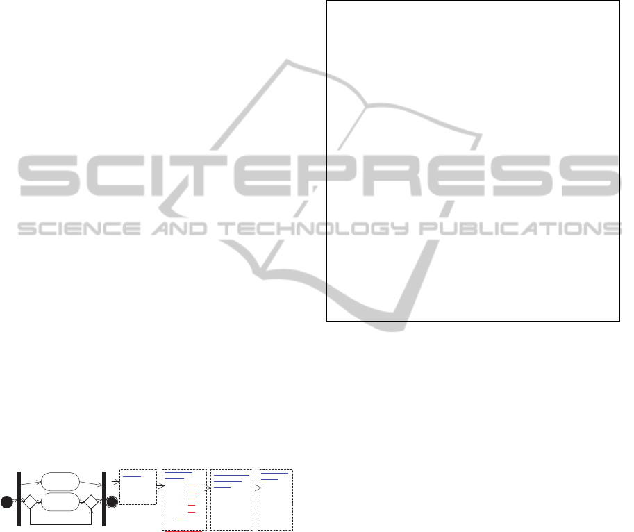
combined (exclusive sub-paths). For example, in
Figure 4, paths p
2
and p
3
contain the same decision
node b, then they are exclusive paths and the number
of combined paths can be reduced from 6 to 4.
A
B
[X>5]
[X<5]
PATHS:
p1: A
p2: X > 5 -B
p3: X < 5
COMBINED
PATHS:
p1 - p2 - p3
p1 - p3 - p2
p2 -p1 -p3
p2 -p1 -p3
p3 -p1 -p2
p3 - p2 -p1
Exclusive paths
REMOVE LAST
EXCLUSIVE
PATHS
p1 - p2
p1 - p3
p2 -p1
p2 -p1
p3 -p1
p3 - p1
COMBINED
PATHS
p1 - p2
p1 - p3
p2 -p1
p3 -p1
Figure 4: Exclusive paths.
Figure 5 shows the algorithm (adapted from
Katayama et al., 1999) to generate test scenarios for
concurrent applications described by an activity
diagram. It starts by scanning all sequential paths on
AD by DFS; if a path contains fork-join nodes, it
scans once more by BFS in order to get concurrent
sub-paths between fork-join. Concurrent sub-paths
obtained in previous step must be combined and
replaced into sequential path obtained in first step.
This algorithm implements the described
restrictions; and, it satisfies the concurrent programs
coverage and adequacy criteria (Katayama et al.,
1999; Sapna and Hrushikesha, 2008; Yan et al.,
2006], and described to follow: (1) Path Coverage
Criterion; each path in a model is executed at least
once in testing. (2) Interaction Coverage Criterion;
all interactions of a concurrent program are executed
at least once in testing.
Input: An activity diagram AD={V,E} where V={A,B,M,F,J,K,a
0
} and E={T};
H = { h
1
, h
2
,..., h
n
}, a set of number of concurrent sub-paths
accessing shared resources for each set of sub-paths SP;
Output: P = {p
1
, p
2
,..., p
n
}, a set of test scenarios.
0: P = ∅ ; /*Set of paths or test scenarios*/
FJP = ∅ ; /*Temporal set of paths containing Fork&Join nodes*/
1: p = Find next path from the initial a
0
to a final node k ∈ K by DFS on AD;
2: sp = Find next sub-path which the first node is a fork f and the last node is a
join j and sp ⊆ p; /*Concurrent tasks*/
2.1: if sp is NOT empty then
SP = Find all sub-paths sp
j
between the nodes f and j
by BFS on AD;
h = Get next in H;/*Num. of sub-paths accessing shared resources in SP*/
2.2: /*Combine all sub-paths sp
j
∈
SP , SP = {sp
1
,sp
2
,...,sp
m
}*/
GSP = ∅ ; /*Combined sub-paths GSP={gsp/gsp⊆SP˄|gsp| = |SP| }*/
GSP = Generate Variations of size h of the sub-paths of the set SP;
for each gsp ∈ GSP /*Update gsp*/
gsp = gsp ∪(SP \ gsp); /*Concatenate with the rest of elements of SP*/
gsp = Keep only the 1
st
sub-path of a set of exclusive sub-paths;
endfor
GSP = Filter equal sub-paths on GSP to avoid redundant sub-paths;
2.3: FJP = Replace the sub-path sp found in Step2 with the combined sub-paths
found in Step 2.2, and create new paths based on paths p ∈ FJP
Go to Step 2; /*Find next concurrent sub-path sp on p*/
2.4: else /* sp is empty; else 2.1*/
if FJP is not empty then
P = P ∪ FJP; FJP = ∅ ; /*Join set of paths to combined paths*/
else
P = P
∪
{p}; /*Update set of paths*/
endif
Go to Step 1;
endif
3: P = Filter equal paths on P to avoid redundant paths;
Figure 5: Test scenarios from activity diagram.
3.3.2 Identifying Test Elements
Next step involves identifying input variables,
conditions and expected results required to exercise
the set of test scenarios. These elements are extracted
from scenario descriptions.
Identifying Input Variables (IT): An Input Variable
is a LEL symbol (object/subject) referenced by a
scenario: (1) Resources of information provided by
external actors or other scenarios; (2) referenced
Actors; (3) Options to choose, optional episode
([Episode Sentence]) generate an input variable and
two conditions: [OK|NOT] (Episode Sentence).
Identifying Conditions (CD): Constraints,
conditions and causes defined into scenario are LEL
symbols (type: state), which describes the different
conditions for input variables (Binder, 2000). (1) If a
resource/actor is not referenced by any constraint,
condition or cause, then this symbol (object/subject)
generates two conditions for testing: actor/resource
= {valid, not valid}. The required condition into test
cases must be valid. (2) If a resource/actor is
referenced by one (or more) constraint, condition or
cause, then this symbol (object/subject) is described
AnAutomatedApproachofTestCaseGenerationforConcurrentSystemsfromRequirementsDescriptions
343
by these conditions: actor/resource = {constraint
*
,
condition
*
, cause
*
}. (3) If a resource/actor has a
unique condition, then it is added the ELSE or NOT
condition: actor/resource = {constraint | condition |
cause, NOT (constraint | condition | cause)}.
Identifying Expected Results (ER): Initially, we
have 2 expected results from the scenario Goal. The
Goal is satisfied when the last episode is executed
and it is not, when some constraint is not satisfized
or some exception is arose (NOT Goal). The
definition of validation actions for expected results
is not covered by this work (Oracle), but the initial
expected results could help to define these actions.
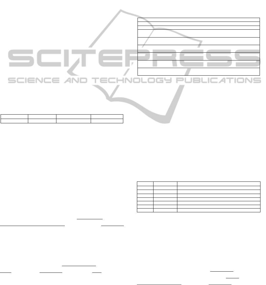
3.3.3 Describing Test Cases
The adopted template to describe test cases was
proposed in (Binder, 2000; Heumann, 2001) and it is
shown in Table 4. The input test values provided
must satisfy the conditions of the input variables
required to exercise a specific test scenario. The third
cell of the Table 4 contains a [Condition] or [N/A].
Condition means that is necessary to supply a data
value satisfying this condition. N/A means that is not
necessary to supply a data value in this case.
Table 4: Template to describe test cases.
Test Case ID Test Scenario Input Test Expected Result
[Condition] / [N/A]
4 CASE STUDIES
In this section, we describe two small case studies
using the proposed approach. These describe
interactions among concurrent activities; so, test
cases derived should be able to uncover
communication, waiting and synchronization errors.
Balance Withdraw of ATM System (Khandai et al.,
2011): Table 3 shows a scenario for this operation.
The steps to complete the scenario were described
by episodes. Lexicon symbols were identified while
scenarios were being built; e.g., ATM Card (object),
ATM Card is not valid (state) and Customer
(subject).
An activity diagram (See Figure 3) was derived
from scenario described in Table 3. IDs of the action
nodes are the same specified in the episodes and
exceptions into scenario, e.g., concurrent episodes 2
and 3 are named like “A2 ATM machine verifies the
Card” and “A3 Customer inserts the PIN”. In this
scenario; we have 8 episodes, which generate 8
action nodes (A1 to A8); 4 exceptions, which
generate 4 action nodes (A2.1, A4.1, A6.1 and
A7.1); 1 sequence of concurrent episodes (A2 and
A3) which generate 1 fork-join structures.
The different paths of the activity diagram
(Figure 3) will exercise a test scenario. In Figure 3,
we have 1 fork-join structure (F1-J1); it executes 2
concurrent sub-paths (A2 and A3). In this case, the
interactions among concurrent sub-paths are not
explicit, so, it’s necessary to combine the sub-paths
in order to test all interactions among them. We have
2 concurrent sub-paths (F1-J1⇒ h1 = 2). Figure 6
shows the set of concurrent test scenarios generated
by our combination strategy.
p
1
: A
0
–A1-A2 <Card is not valid> A2.1- K1
p
21
: A
0
–A1-A2 <Not(Card is not valid)> A3-A4 <PIN is not valid> A4.1-K2
p
22
: A
0
–A1-A3-A2 <Not(Card is not valid)> A4 <PIN is not valid> A4.1- K2
p
31
: A
0
-A1-A2 <Not(Card is not valid)>A3-A4<Not(PIN is not valid)> A5-A6-<Account
operation = Account affirm> A6.1-K3
p
32
: A
0
-A1-A3-A2 <Not(Card is not valid)> A4<Not(PIN is not valid)> A5-A6-<Account
operation = Account affirm> A6.1-K3
p
41
: A
0
-A1-A2 <Not(Card is not valid)>A3-A4<Not(PIN is not valid)> A5-A6-<Not(Account
operation = Account affirm)> A7-<Balance is not Ok>-A7.1-K4
p
42
: A
0
-A1-A3-A2 <Not(Card is not valid)>A4<Not(PIN is not valid)> A5-A6-<Not(Account
operation = Account affirm)> A7-<Balance is not Ok>-A7.1-K4
p
51
: A
0
-A1-A2 <Not(Card is not valid)>A3-A4<Not(PIN is not valid)> A5-A6-<Not(Account
operation = Account affirm)> A7-<Not(Balance is not Ok)>-A8-K5
p
52
: A
0
-A1-A3-A2 <Not(Card is not valid)> A4<Not(PIN is not valid)> A5-A6-<Not(Account
operation = Account affirm)> A7-<Not(Balance is not Ok)>-A8-K5
Figure 6: Test scenarios for ATM system.
The input variables and conditions that exercise the
test scenarios are extracted from scenario described
in Table 3. The input variables (IT) are extracted
from resources (e.g., ATM Card, PIN, Balance and
Account operation) and from actors (e.g., Customer,
ATM Machine and Bank). Table 5 shows the
conditions (CD) extracted from the exceptions. And,
the initial set of expected results (ER) for the main
flow and the exceptions were extracted from the
“Goal”: Withdraw the balance and NOT Withdraw
the balance.
Table 5: Input variables and conditions.
ID Variable Variable Condition (Category)
V1
ATM Card Card is not valid | Not(Card is not valid)
V2
PIN PIN is not valid | NOT(PIN is not valid)
V3
Account operation Ac. operation = Account affirm | Not(Ac. operation = Account affirm)
V4
Balance Balance is not Ok | NOT(balance is not Ok)
V5
Customer Valid | NOT Valid
V6
ATM Machine Available | NOT Available
V7
Bank Available | NOT Available
Table 6 shows the test cases generated for an “ATM
System” scenario. From input variables and
conditions, we can generate representative values
for testing. This process will require human
intervention and our approach leaves this open.
Shipping Order System (Sabharwal et al., 2011):
Table 7 shows a scenario to complete an order sent
by a customer. Underlined lowercase words or
phrases are symbols of lexicon, e.g., Stock (object),
Stock not available (state) and Customer (subject).
ICEIS2014-16thInternationalConferenceonEnterpriseInformationSystems
344
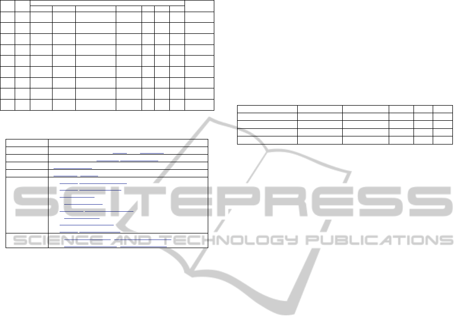
Table 6: Test cases generated from scenario (Table 3).
TCID TSID
In
p
ut Test [Condition] / [N/A]
Expected
Result
V1 V2 V3 V4 V5 V6 V7
TC1 p
1
Card is not
valid
N/A N/A N/A Valid Avail. Avail. Not Withdraw
the balance
TC2 p
21
Not(Card is
not valid)
PIN is not
valid
N/A N/A Valid Avail. Avail. Not Withdraw
the balance
TC3 p
22
Not(Card is
not valid)
PIN is not
valid
N/A N/A Valid Avail. Avail. Not Withdraw
the balance
TC4 p
31
Not(Card is
not valid)
Not(PIN is
not valid)
Account operation =
Account affirm
N/A Valid Avail. Avail. Not Withdraw
the balance
TC5 p
32
Not(Card is
not valid)
Not(PIN is
not valid)
Account operation =
Account affirm
N/A Valid Avail. Avail. Not Withdraw
the balance
TC6 p
41
Not(Card is
not valid)
Not(PIN is
not valid)
Not(Account oper. =
Account affirm)
Balance is
not Ok
Valid Avail. Avail. Not Withdraw
the balance
TC7 p
42
Not(Card is
not valid)
Not(PIN is
not valid)
Not(Account oper. =
Account affirm)
Balance is
not Ok
Valid Avail. Avail. Not Withdraw
the balance
TC8 p
51
Not(Card is
not valid)
Not(PIN is
not valid)
Not(Account oper. =
Account affirm)
Not(Balance
is not Ok)
Valid Avail. Avail. Withdraw the
balance
TC9 p
52
Not(Card is
not valid)
Not(PIN is
not valid)
Not(Account oper. =
Account affirm)
Not(Balance
is not Ok)
Valid Avail. Avail. Withdraw the
balance
Table 7: Shipping order system scenario.
Title
SHIPPING ORDER SYSTEM
Goal
Complete the requested Order by a Customer.
Context
- Pre-conditions: customer SEND ORDER.
Resources
Stock, Payment.
Actors
Customer, System.
Episodes
1. System RECEIVE ORDER.
2. System CHECK STOCK.
3. FILL ORDER.
4. # PACK ORDER.
5. Customer MAKE PAYMENT. #
6. # SHIP ORDER.
7. ACCEPT PAYMENT. #
8. System CLOSE ORDER.
Exceptions
2.1. Stock not available (NOTIFY CUSTOMER).
5.1. Payment not received (CANCEL ORDER).
5 RESULTS
Balance Withdraw of ATM System (Khandai et al.,
2011): A2 “Card verification” and A3 “PIN
entering” are done concurrently. When an exception
is arose or the Card is not valid (A2), a
communication problem must be detected by the
ATM system because A3 waits by a signal from A2
to complete. It is detected in test case “TC1”.
Although A2 and A3 are done concurrently, there
is communication (interleaving) among them
because they send and receive signals to completion.
A3 Customer enters the card PIN process waits by
A2 Card verification process to completion. These
communication problems are tested in test cases
TC3, TC5, TC7 and TC9. TC2, TC4, TC6 and TC8
are executed with right communication order.
Shipping Order System (Sabharwal et al., 2011): A4
“PACK ORDER” and A5 “MAKE PAYMENT” are
done concurrently. When the Payment is not
received (A5), a communication problem is detected
by the system because A4 waits by A5 to complete.
This problem is detected by our approach.
Sabharwal et al. (2011) detected only one test
scenario because it is based on priority.
Table 8 presents a summary of the obtained
results for the ATM System and Shipping Order
scenarios; these studies detected 4 interactions more
than Khandai et al. (2011), and 6 more than
Sabharwal et al. (2011). These are the
communication errors between concurrent process.
These studies demonstrate that the lexicon
symbols referenced into scenario allow us to detect
interaction among concurrent tasks and reduce the
number of test scenarios, leading us to believe that
our approach is also an efficient alternative to
generate test cases for concurrent applications.
Table 8: Comparing results.
Approach Case Study #Test Scenarios Comms Waits Syncs
Khandai et al. 2011 ATM System 5 5
Our approach ATM System 9 4 4 1
Sabharwal et al., 2011 Shipping Order 1 1
Our approach Shipping Order 7 5 2
6 RELATED WORK
We have not found approaches to generate test cases
for concurrent applications from requirements
described in natural language specifications.
Usually, UML activity and sequence diagrams are
used for testing concurrency; however, most of
reviewed works do not attend the characteristics
defined by Katayama et al. (1999). And, it is
necessary to refine the input models into
intermediate models (not automated) to make
explicit test inputs or conditions of them.
Some test generation methods based on path
analysis of activity diagrams which contain fork-join
structures were proposed, and for test scenario
explosion problem: Sabharwal et al. (2011) use a
prioritization technique based on information flow
and genetic algorithms; in (Sapna and Hrushikesha,
2008; Shirole and Kumar, 2012) are used the
precedence information among concurrent activities
(activities in test scenarios are combined based on
the order of Send Signal and Accept Event actions).
Communication and wait interactions are considered
in (Sapna and Hrushikesha, 2008; Shirole and
Kumar, 2012). In (Khandai et al., 2011), a sequence
diagram is converted into a concurrent composite
graph (variant of an activity diagram); then they
applied DFS search technique to traverse the graph,
BFS search algorithm is used between fork and join
construct to explore all concurrent nodes. In (Kim et
al., 2007) an activity diagram is mapped to an
Input/Output explicit Activity Diagram (explicitly
shows external inputs and outputs); this diagram is
converted to a directed graph for extraction of test
scenarios and test cases (Basic path). In (Khandai et
al., 2011; Kim et al., 2007) are not took care of
communication interactions. Debasish and Debasis
(2009) proposed an approach to generate test cases
AnAutomatedApproachofTestCaseGenerationforConcurrentSystemsfromRequirementsDescriptions
345

from activity diagrams, which are generated
intermediate models; intermediate models are built
to identify and refine input and output variables;
these tasks are automated, but they could be
expensive and time consuming; objects created and
changed by activities are considered as test
information. Yan et al. (2006) generated test
scenarios from BPEL (Business Process Execution
Language) specifications; the scenario explosion
problem is solved using path combination and
exclusive paths strategies, communication
interactions are not considered. Katayama et al.
(1999) proposed an approach to generate test cases
based on Event InterActions Graph and Interaction
Sequence Testing Criterion, graph model represents
the behavior of concurrent programs and the
different interactions among unit programs.
Most of approaches to derive test cases are based
on path analysis of semi-formal behaviour models.
There are no systematic approaches to derive test
cases from natural language requirements
descriptions - use cases or scenarios and which use
the relevant words (shared resources) of the
application - lexicon to identify concurrent task
interactions and reduce the test scenarios. Our
approach derives test cases from scenarios, the input
variables, conditions, expected results and
concurrent tasks are identified and described before
the derivation of intermediate models (graphs); and
the reduction of test scenarios number is based on
task interactions by shared resources.
7 CONCLUSIONS
Our approach provides benefits due to the following
reasons: (1), it is capable to detect interaction errors
among concurrent tasks more comprehensively than
the existing approaches. (2), it derives test cases from
requirements descriptions based on semi-structured
natural language, existing approaches are based on
semi-formal models. (3), it reduces the number of
test scenarios generated for concurrent applications.
(4), it starts with the software development process
and these processes are carried out concurrently.
In our approach each concurrent sub-path has a
single action; future work will be considered sub-
paths containing a flow of actions.
In the future, we plan to deal with: (1) Testing of
exceptions and non-functional requirements
(constraints/conditions on resources); in this work
was shown some criteria for mapping exceptions and
non-functional requirements descriptions to behavior
models and testing. (2) Reduction of test scenarios
number based on precedence (interleaving); our
approach make explicit the interactions among
concurrent tasks; however, shared resources could
enforces a precedence order, e.g., when a task
depends on a signal sent from other task to notify
that a variable was updated (communications). (3)
An automated tool that implements our approach is
being developed (C&L - http://pes.inf.puc-rio.br/cel)
to support the proposed strategy.
REFERENCES
Binder, R. V., 2000. Testing object-oriented systems.
Addison-Wesley.
Cockburn, A.,2001. Writing Effective Use Cases.
Addison-Wesley.
Damas, C., Lambeau, B., Dupont, P. and Lamsweerde, A.
v., 2005. Generating annotated behavior models from
end-user scenarios. IEEE TSE, volume 31, number 12.
Debasish, K. and Debasis, S., 2009. A novel approach to
generate test cases from UML activity diagrams.
Journal of Object Technology, volume 8, number 3.
Denger, C. and Medina, M., 2003. Test Case Derived from
Requirement Specifications, Fraunhofer IESE Report.
Gutiérez, J. J., Escalona, M. J., Mejías, M. and Torres, J.,
2006. An approach to generate test cases from use
cases, Proceedings of the 6th International Conference
on Web Engineering, pages 113-114.
Heitmeyer, C., 2007. Formal methods for specifying,
validating, and verifying requirements. J Univ Comput
Sci, volume 13, number 5, pages 607-618.
Heumann, J.,2001 Generating test Cases from use cases IBM
Katayama, T., Itoh, E. and Furukawa, Z., 1999. Test-case
generation for concurrent programs with the testing
criteria using interaction sequences. Asia-Pacific
Software Engineering Conference.
Khandai, M., Acharya, A. and Mohapatra, D., 2011. A
Novel Approach of Test Case Generation for
Concurrent Systems Using UML Sequence Diagram.
ICECT, 6, pages 157-161.
Kim, H., Kang, S., Baik, J., Ko, I., 2007. Test Cases
Generation from UML Activity Diagrams. In 8
th
ACIS
International Conference on Software Engineering,
Artificial Intelligence, Networking, and Parallel/
Distributed Computing, pages 556-561.
Leite, J. C. S. P., Hadad, G., Doorn, J. and Kaplan, G.,
2000. A scenario construction process. Requirements
Engineering Journal, Springer-Verlag London Limited,
volume 5, number 1, pages 38-61.
Letier, E., Kramer, J., Magee, J. and Uchitel, S., 2005.
Monitoring and Control in Scenario-based
Requirements Analysis. ICSE.
Sabharwal, S., Sibal, R. and Sharma, C., 2011. "Applying
Genetic Algorithm for Prioritization of Test Case
Scenarios Derived from UML Diagrams". IJCSI, 8.
Sapna, P. G. and Hrushikesha, M., 2008. Automated
Scenario Generation Based on UML Activity
ICEIS2014-16thInternationalConferenceonEnterpriseInformationSystems
346

Diagrams. In Proceedings of the International
Conference on Information Technology.
Shirole, M. and Kumar, R., 2012. Testing for concurrency
in UML diagrams. SIGSOFT Softw. Eng. Notes,
volume 37, number 5.
Sparx, 2011. Writing use case scenarios for model driven
development. http://www.spaxsystems.com.
Yan, J., Li, Z., Yuan, Y., Sun, W. and Zhang, J., 2006.
BPEL4WS Unit Testing: Test Case Generation Using
a Concurrent Path Analysis Approach. In Proceedings
of ISSRE’06, pages 75-84.
AnAutomatedApproachofTestCaseGenerationforConcurrentSystemsfromRequirementsDescriptions
347
