
ICT-enabled Medical Compression Stocking for Treatment
of Leg Venous Insufficiency
Troels Fedder Jensen
1
, Finn Overgaard Hansen
1
, Jos
´
e Antonio Esparza Isasa
2
,
Peter Høgh Mikkelsen
1
, Tomi Hakala
3
and Timo Vuorela
4
1
Aarhus University School of Engineering, Finlandsgade 22, Aarhus, Denmark
2
Department of Engineering, Aarhus University, Finlandsgade 22, Aarhus, Denmark
3
Department of Material Science, Tampere University of Technology, Korkeakoulunkatu 6, Tampere, Finland
4
Department of Electronics and Communications Engineering, Tampere University of Technology,
Korkeakoulunkatu 3, Tampere, Finland
Keywords:
Compression Therapy, Leg Venous Insufficiency, Intelligent Medical Compression Stockings, Wearable
Devices, Independent Living.
Abstract:
This paper presents a novel approach to the treatment of leg venous insufficiency. This approach consists of
an ICT-enabled medical compression stocking that aims at mitigating the requirement for daily assistance and
increasing the patient’s self-sufficiency. More specifically, this paper presents the wearable subsystem of this
solution. In addition this paper discusses the different prototypes that have been produced to demonstrate that
this new approach is technically feasible.
1 INTRODUCTION
Leg venous insuffiency is a serious medical condition
with severe impact on the mobility and self-suffiency
of patients, chiefly elderly people. The most practical
and efficient non-invasive treatment to counteract and
prevent leg venous problems is compression therapy
by means of bandages or Graded Compression Stock-
ings (GCSs) (Partsch, 2003). GCSs, however, suffers
from a number of drawbacks: Poor conformance to
the individual patients’ legs as their size and volume
changes over time, degrading elasticity over time due
to washing and stretching, and difficult to handle. The
overall consequence of this is poor levels of therapeu-
tic compliance and consequently less effective treat-
ment. This, in turn, may lead to ineffective and pro-
longed treatment, and reduced quality of life. More-
over, as GCSs are often difficult to put on by patients
by themselves, the patients often depend on a visit by
home caretakers in the morning and evening to help
put the GCSs on and take them off. Apart from being
of obvious inconvenience for the patients, it is a de-
manding and time-consuming task for the caretakers,
and of substantial expense to society.
In this paper we present the current state of the
Stocking Assembly (SA) subsystem (Figure 2) of
the e-Stocking EU Ambient Assisted Living project.
The aim of this project is to develop an intelligent,
Information and Communication Technology (ICT)-
enabled graded compression stocking solution that
addresses the aforementioned shortcomings of exist-
ing GCSs. Key features of the novel stockings are
easy application and operation, compliance with indi-
vidual patient’s clinical needs; and enhanced mobility
and self-sufficiency.
Section 2 presents the state of the art in GCSs and
ICT-enabled compression solutions. Sections 3 to 5
yield an overview of the entire e-Stocking architec-
ture, pertaining requirements, and the design of the
SA adopted to meet these requirement. Sections 6 to 7
yield a description of SA prototypes, obtained results,
future work and conclusions.
2 STATE OF THE ART
Current approaches to treatment of leg venous insuffi-
ciency focus on the compression of the affected limb
through different mechanisms. Existing compression
therapy treatment is delivered by the application of ei-
ther compression bandages, compression stockings or
Intermittent Pneumatic Compression (IPC) (Hegarty
212
Jensen T., Hansen F., Esparza Isasa J., Mikkelsen P., Hakala T. and Vuorela T..
ICT-enabled Medical Compression Stocking for Treatment of Leg Venous Insufficiency.
DOI: 10.5220/0004903402120217
In Proceedings of the International Conference on Biomedical Electronics and Devices (BIODEVICES-2014), pages 212-217
ISBN: 978-989-758-013-0
Copyright
c
2014 SCITEPRESS (Science and Technology Publications, Lda.)

et al., 2010). IPC is targeted primarily for the treat-
ment of venous leg ulcers and is delivered in hospitals
and daycare centers (Hegarty et al., 2008). While re-
lated in nature to the problem under study the IPC ap-
proach does not address the patients’ self-sufficiency
and the characteristics of the treatment are different as
IPCs provide dynamic compression while this study
aims at static compression at lower pressure levels.
Application of a graded pressure distribution by
means of GCS is a complex task and previous work
describes how this is true, even for ideal scenar-
ios (Liu et al., 2005). Additional studies have shown
that muscle movement during walking results in a
variation of up to 30 mmHg in exerted pressure
(Godoy et al., 2010; Partsch et al., 2006), making the
study of the pressure distribution over the leg even
more challenging. However, from a medical point
of view such variations are positive as they provide
a measure of dynamic compression that massages the
leg.
In order to measure the compression exerted at
specific locations, resistive force sensors have been
extensively evaluated (Khaburi et al., 2011a; Kawano
et al., 2005) and to some extent pneumatic force sen-
sors e.g. in the shape of the commercially avail-
able Microlab PicoPress pressure sensor instrument
(Khaburi et al., 2011b). Finally, monitoring the
swelling process of the leg as the treatment pro-
gresses has also been previously addressed using
bioimpedance techniques (Hegarty et al., 2008) and
strain gauges (Lebosse et al., 2011).
Even though extensive work has been conducted
on different aspects of the treatment of leg venous
insufficiency such as sensing technologies, sensor
placement and analysis of existing approaches, to our
knowledge an electronic wearable device that deliv-
ers quality compression treatment and enhances the
patient’s self-suffiency has not yet been developed.
3 SYSTEM ARCHITECTURE
The e-Stockings system consists of several physically
separated subsystems shown on Figure 1.
Figure 1: e-Stockings System Architecture.
The SA provides the compression to the patient’s
leg. Through the use of several air chambers the com-
pression applied to the patient’s leg can be graded
from ankle level to just below the knee. The com-
pression delivered to the leg is continuously regu-
lated through measurement of the air pressure in the
air chambers or the on-skin pressure. The compres-
sion applied is calibrated to each individual patient by
means of the E-stockings Calibration Device (ECD).
The ECD provides calibration data to the SA con-
trol unit and interfaces pressure sensors which can be
applied with the SA. The ECD is used to obtain on-
skin pressure values against which the SA can cali-
brate its target pressure values.
The Gateway consists of a smartphone device
which runs a gateway application. This provides
bridging services when the SA and ECD should be
connected as well as the graphical user interface for
use in the calibration process. The Gateway connects
wirelessly to the SA and ECD, respectively, and for-
wards sensor data requests and responses to the coun-
terpart. In the future, the Gateway is envisioned to
provide a means of remotely configuring and obtain-
ing system and medical diagnostics data from the SA.
4 SYSTEM REQUIREMENTS
The requirements for the system as a whole, to which
the SA must adhere, are specified in detail in the per-
taining SysML-based Systems Requirement Specifi-
cation, in which functional requirements are specified
using a set of use cases. The most important require-
ments for the SA are informally listed below. The
e-Stocking shall...
R1 promote self-sufficiency; the user shall be able
to apply and remove the stocking without assis-
tance.
R2 apply the correct compression profile, typically
with the highest compression in the foot section
and decreasing in compression towards the knee.
R3 apply the correct compression throughout the us-
age scope of the stocking, even in the face of
changing leg size.
R4 be user-friendly in its operation.
R5 be battery powered and operable for 14 hours
without charging.
R6 be breathable and washable.
R7 be as lightweight and noiseless as possible.
R8 have a compression mechanism and control box
which is easily attached and detached.
R9 be configurable, enabling changes in compression
configurations.
ICT-enabledMedicalCompressionStockingforTreatment
ofLegVenousInsufficiency
213
R10 have an aesthetically pleasing design.
R11 be certifiable as a medical device.
As the e-Stocking will compete with normal GCSs
in the market, which are very thin with a look and
feel as normal knitted stocking, and as the require-
ments are contradictory (e.g. lightweight, but battery-
powered, breathable but airtight), these requirements
give rise to substantial challenges.
5 SA DESIGN
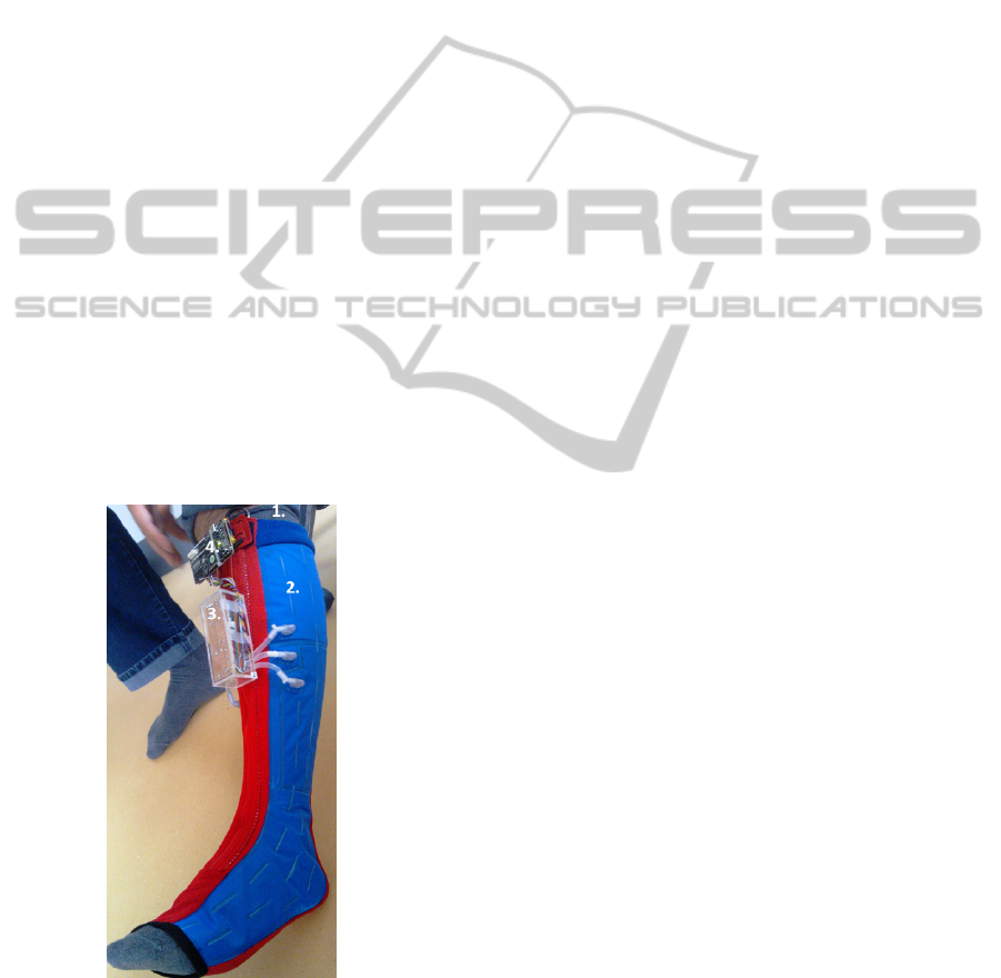
The SA consists of four main parts as shown on Fig-
ure 2: an inner stocking (item 1), the compression
stocking itself (item 2), an actuator board (item 3),
and an Electronic Control Unit (ECU) (item 4). Each
of these are described in the following subsections.
5.1 Inner Stocking
The inner stocking is a commercial, knitted stocking,
which has an antibacterial property (Ag). The purpose
of this stocking is to provide a smooth, comfortable
surface to the skin. Furthermore, as this is the part
of the stocking assembly which is in immediate con-
tact with the patient’s skin, it alleviates the stocking
itself from the majority of washing required to main-
tain proper hygiene.
Figure 2: Stocking Assembly prototype 3.
5.2 Stocking
The stocking, as shown on Figure 2 item 2, covers the
lower leg of the patient from just behind the toes to
immediately under the knee. A a nonseparable zip-
per, extending the full length of the front of the stock-
ing save for the last centimeter on the foot, provides
a closing mechanism which allows the stocking to be
applied and removed with relative ease, much like a
softer version of a knee-long boot, while ensuring a
snug fit. The top of the stocking consists of a soft,
elastic band which prevents the stocking from sagging
when it is zipped but not yet compressed. The stock-
ing has 3 individual compression sections mounted
laterally to cover the entire length of the stocking.
Each compression section consists of two air cham-
bers mounted at same height on the adaxial and abax-
ial sides of the leg, respectively. The air chambers are
sewn to an elastic, permeable garment on the ante-
rior and posterior sides of the leg to form the integral
stocking. Each air chamber consists of two layers of
airtight material which are high-frequency welded at
the edges to achieve air tightness. A special air chan-
nel is welded from the foot section along the front of
the middle compression section to allow a shorter tube
to connect the actuator board and the foot section. The
two layers of which each air chambers consists differ
in rigidity, the outer layer being more rigid than the
inner one, ensuring that expansion of the air chamber
is primarily directed towards the patient’s leg which
increases the compression applied to the leg per unit
volume of air in the compression section.
By controlling the compression of each compres-
sion section individually, the requirement for graded
compression can be accommodated. The expandable
compression sections provide the stocking with a cer-
tain dynamic range which is foreseen to alleviate the
need for individual tailoring of the stockings. Instead,
this may allow for the production of only a limited
number of different shapes and sizes, which will sim-
plify sizing, ordering and distributing of the stock-
ings.
5.3 Electronic Control Unit
Compression is managed by an Electronic Control
Unit (ECU). The ECU controls sensors, actuators,
user input and other external interfaces by means of
a software application running atop a FreeRTOS (RT
Engineers Ltd., 2013) Operating System (OS).
The nature of the experimental work conducted
in this project requires frequent changes in sensors
and actuators interfaced by the ECU. In order to ease
this process and shorten development time and cost
we use the Programmable System-on-Chip Cypress
PSoC5 as hardware platform. This platform imple-
ments an ARM Cortex-M3-based processor which
provides sufficient processing power to run the appli-
BIODEVICES2014-InternationalConferenceonBiomedicalElectronicsandDevices
214

cation and OS, apart from a number of programmable
hardware blocks which provides the necessary flexi-
bility, e.g. for conditioning sensors and actuators sig-
nals. Using custom hardware blocks implemented in
the PSoC5 allows a small form-factor to be main-
tained, yet preserves an open interface for experi-
menting with different sensors and actuators. Further-
more, the ECU features a dedicated Bluetooth module
to connect to remote devices, a 3-axis accelerome-
ter for motion detection and power for the complete
Stocking Assembly.
C++ was selected as implementation language.
The use of an object-oriented (OO) language
promises to minimize the gap between the employed
OO design process and the implementation. Fur-
thermore, C++ paves the way for flexible and inter-
changeable implementations, a desirable feature in
light of the experimental nature of the prototyping
and subsequent frequent alterations and additions to
source code, e.g. when testing a new sensor or actu-
ator, or a new compression strategy. Finally, the use
of C++ allows source code to be tested early, often
and systematically as an integrated quality-enhancing
activity throughout software development.
While not strictly necessary, the inclusion of an
OS was desired. It was envisioned that the ECU appli-
cation would benefit from running a number of con-
current threads, and the task abstraction, timing and
synchronization facilities, etc. provided by an OS
would be of substantial value. A number of OS’s
were investigated and FreeRTOS subsequently cho-
sen due to its flexibility, customizability, widespread
use and small footprint. An abstraction layer was put
atop FreeRTOS to allow the application to interface
and abstract away the specific OS, and thus facilitate
a change of OS if so desired later, e.g. to SafeR-
TOS (WHIS, 2013) as required in a certification pro-
cess.
5.4 Sensors and Actuators Board
The sensors and actuators board, mounted on the
front of the stocking as shown on Figure 2 item 3,
is equipped with four miniature solenoid valves, one
air pump and an electronic manometer, mounted on a
prototyping PCB and placed in a plexiglas housing.
The actuators and manometer are connected inside
this housing using short pieces of tubing. Three short
tubes protrude from each side of the actuator board
and are inserted into the flanges of the stocking com-
pression sections prior to compression. This allows
the ECU to measure pressure in, and control inflation
or deflation of the individual compression sections.
6 PROTOTYPES AND RESULTS
This section presents three preliminary system proto-
types and the results that have been achieved so far.
6.1 Prototype 1: Resitive Sensor
Solution
In Prototype 1 resistive force sensors were used to
measure the on-skin pressure. In preparation for this,
a number of tests were conducted to screen for suit-
able sensors. This was done using a cardboard tube
of est. 10 cm diameter upon which the sensor was
mounted. On top of this, the sensor pad of a PicoPress
compression measurement system was positioned for
reference readings. To apply pressure to the sensors,
the cuff of a sphygmomanometer was wrapped around
the cardboard tube, covering the sensors.
It was evident from these experiments that a suit-
able resistive force sensor should have certain prop-
erties, most notably a large sensing area to mitigate
edge effects. It was also evident that, regardless of
the sensor used, pressure measurements below 10-15
mmHg were not consistent and could not be trusted.
As a result of the screening process, the Inter-
Link Electronics FSR 406 Square Force Sensing Re-
sistor (Interlink Electronics, 2013) was selected for
use in the prototype.
For the experiments on the prototype, three FSR
406 sensors were used to measure on-skin pressure.
One sensor was positioned on the back of the leg and
on the calf, respectively, corresponding to positions
B1 and C recommended in (Partsch et al., 2006), and
one sensor was positioned above the tuberiosity of
the third metatarsal bone on the foot. Each pressure
sensor was connected to the ECU by discrete wires.
A number of compression-regulation-decompression
cycles were executed: The ECU controlled compres-
sion build-up until the specified compression level
was reached, at which point the ECU commenced
periodic regulation of the compression level, supple-
menting compression as made necessary by any air
leakage from the sections. When commanded to do
so, the ECU controlled decompression of the stock-
ing until the compression reached a level at which the
SA was considered deflated.
A number of results were drawn from these exper-
iments. First, it was evident that the exact positioning
of the pressure sensors was crucial to the repeatability
of the experiments; placing the sensors even 1 cm off
caused intolerable deviations in the measured com-
pression. Second, the airtightness of the compression
sections was insufficient.
The requirement for very exact positioning of the
ICT-enabledMedicalCompressionStockingforTreatment
ofLegVenousInsufficiency
215

resistive force sensors was considered an unaccept-
able task to put on the patients which were to apply
the stocking on a daily basis. To alleviate this, it was
considered to permanently attach the sensors to the
inside of the stocking. This would require the sen-
sors to be washable, however, which they are not by
default. Thus, they would have to be coated in wa-
tertight material. Experiments using coated sensors
showed that the coating caused its own set of prob-
lems, as it clogged the small breathing hole in the sen-
sor necessary for air to escape from the sensor when
it is compressed.
It was also clear that the airtightness of the com-
pression sections was insufficient, as the ECU had
to supplement the compression by running the pump
and valves every 5-10 seconds. This caused an audi-
ble periodic noise disturbance and significantly higher
power consumption over time, both of which were un-
acceptable.
Based on these results it was decided to discard
resistive sensors altogether, and create and test a new
prototype which would be more airtight, and which
would use an electronic manometer to measure the
pressure in the compression sections and use this to
determine the compression on the patient’s leg.
6.2 Prototype 2: Manometer Solution
Prototype 2 was constructed to be more airtight and
using a Smartec SPD002GAsil manometer (Smartec
sensors, 2013) to gauge pressure in the air chambers.
This would have the benefit that the sensor would
not need to be permanently attached at skin level and
could thus be removed along with other electronic and
pneumatic devices prior to washing.
As experiments progressed it became evident that
the air chambers were indeed more airtight due to im-
provements achieved in the high-frequency welding
process, but not entirely so. It also became evident
that the pressure measured in the compression sec-
tions did not correspond to the applied compression
on the skin as measured on-skin by the PicoPress ref-
erence sensor. It was possible to derive a second order
compression section-to-skin pressure transfer func-
tion, but such a transfer function proved susceptible
to changes in the volume and shape of the test per-
son’s leg - changes which were expected as a con-
sequence of the compression treatment itself. Con-
sidering the desire for not having to tailor the stock-
ings to individual patients, and considering that even
if tailored, any change in leg shape or volume, e.g. as
result of compression therapy, would render a trans-
fer function erroneous, the use of the manometer-and-
transfer-functions combination was discarded.
6.3 Prototype 3: Hybrid Solution
Prototype 3 was constructed to leverage the experi-
ence gained from prior prototypes; to use on-skin cal-
ibration periodically, e.g. monthly, to obtain accurate
reference results, and to use the corresponding ECU
manometer values as target values on a day-to-day ba-
sis.
The ECD was introduced to provide a means of
gauging the on-skin pressure through the use of three
FSR 406 resistive force sensors, identical to the ones
used in Prototype 1 and placed in the same positions.
The stand-alone ECD was to be operated by skilled
personnel which would mitigate the risk of false com-
pression readings due to errornous positioning of the
sensors. The ECU would be commanded into a spe-
cial ”calibration” mode in which it would control the
compression of the leg as hitherto, but take its com-
pression readings from the ECD over a Bluetooth con-
nection established by a Gateway device (Smartphone
app). When the on-skin compression level as read by
the ECD was in accordance with the target compres-
sion configured for the ECU, the ECU would stop
compression of the leg, gauge the level of compres-
sion in the individual compression sections by means
of its own electronic manometer and store these in
non-volatile memory for future use when operating in
its ”normal” mode. Thus, using the ECD and ECU in
conjunction, the stocking could be calibrated by the
help of skilled personnel periodically (e.g. monthly)
to accomodate changes in the shape and volume of
the patient’s leg, but be used with relative ease by the
patients themselves, as there would be no need for ac-
curate placement of sensors on a day-to-day basis.
Experiments were conducted using this strategy
and, while the principle appeared sound, it again be-
came evident that the spot measurements given by the
resistive sensors were not sufficiently reliable. It was
therefore decided that a number of flat stand-alone
air chambers (dubbed ”calibration pads”) each the
size of a compression sections, should be produced.
For calibration, the calibration pads would be slightly
inflated, connected to electronic manometers on the
ECD and placed under the stocking before it was
closed. When compression was initiated, the same
pressure would be exerted on the calibration pads as
on the skin. Thus, by measuring the pressure in the
calibration pads, a measure for the on-skin pressure
could be derived. While similar to the resistive sen-
sors in application, the prominent advantage of the
calibration pads is their larger area; pressure readings
taken from a calibration pad corresponds to the mean
compression exerted on the area covered by the pad
BIODEVICES2014-InternationalConferenceonBiomedicalElectronicsandDevices
216

and thus mitigates the requirement for very ex-
act positioning of the sensors.
7 FUTURE WORK AND
CONCLUSIONS
Initial tests have been conducted using the calibration
pads. The results indicate a correlation between com-
pression measured with the pads and with a PicoPress
reference, but further experiments must be conducted
to fully understand and have confidence in the corre-
lations, especially in terms of consistency over time.
Clinical testing is planned to take place during the
final year of the project. This test shall primarily re-
veal if the stocking has the required clinical effect on
the patient’s legs. Before this testing phase can take
place, however, certification by legal authorities in the
country where the test is to be performed - in our
case in Switzerland - must be obtained. Another sim-
ilar task, end-user testing, is planned to be conducted
in three different countries to investigate and accom-
modate for cultural differences and habits. The end-
user testing shall primarily test the main requirements
of enabling independent living and usability aspects.
End-user tests also require certification to be obtained
prior to the tests.
Based on the results of clinical and end-user tests,
the prototype will be further developed and, at the end
of the project period, result in a workable prototype
which fulfils the stated set of requirements. At this
time, the experiences obtained and the final prototype
will form the foundation for further product develop-
ment and maturing, in which manufacturing and pro-
duction issues will be addressed and CE-marking ob-
tained for the end product, paving the way to intro-
duction into the market.
This paper has listed the main requirements of
an ICT-controlled medical compression stocking, and
described the design, implementation, and tools ap-
plied in the development of a stocking assembly to
meet these requirements. Furthermore, it has de-
scribed the technical challenges posed and how they
were overcome.
ACKNOWLEDGEMENTS
This research is funded by the EU Ambient Assisted
Living Joint Programme, eStockings Project under
grant agreement no. AAL-2011-4-020.
REFERENCES
Godoy, J., Braile, D., Perez, F., et al. (2010). Effect of walk-
ing on pressure variations that occur at the interface
between elastic stockings and the skin. International
Wound Journal, 7(3):191–193.
Hegarty, M., Grant, E., and Reid, L. (2010). An overview
of technologies related to care for venous leg ulcers.
Information Technology in Biomedicine, IEEE Trans-
actions on, 14(2):387–393.
Hegarty, M., Grant, E., Reid, L., and Henderson, T. (2008).
A dynamic compression system for improving ulcer
healing: Design of a sensing garment. In Multisensor
Fusion and Integration for Intelligent Systems, 2008.
MFI 2008. IEEE International Conference on, pages
551–556.
Interlink Electronics (2013). http://
www.interlinkelectronics.com/FSR406.php. Interlink
Electronics official website for FSR 406 single-zone
Force Sensing Resistor accessed 6-11-2013.
Kawano, T., Hishida, S., and Hashimoto, M. (2005). Devel-
opment of measuring device for lower leg swelling us-
ing a strain gauge. JSME International Journal, 48(4).
Khaburi, J. A., Dehghani-sanij, A. A., Nelson, E. A., and
Hutchinson, J. (2011a). Measurement of Interface
Pressure Applied By Medical Compression Bandages.
In International Conference on Mechatronics and Au-
tomation, volume 01, pages 289–294.
Khaburi, J. A., Dehghani-sanij, A. A., Nelson, E. A., and
Hutchinson, J. (2011b). The Use of PicoPress Trans-
ducer to Measure Sub-Bandage Pressure. In World
Academy of Science, Engineering and Technology,
pages 267–271.
Lebosse, C., Renaud, P., Bayle, B., and De Mathelin, M.
(2011). Modeling and evaluation of low-cost force
sensors. Robotics, IEEE Transactions on, 27(4):815–
822.
Liu, R., Kwok, Y. L., et al. (2005). Objective evaluation
of skin pressure distribution of graduated elastic com-
pression stockings. American Society for Dermato-
logic Surgery, pages 615–624.
Partsch, H. (2003). Evidence based compression therapy.
VASA, Journal of Vascular Diseases, pages 3–39.
Partsch, H., Clark, M., Bassez, S., et al. (2006). Measure-
ments of lower leg compression in vivo: Recommen-
dations for the performance of measurements of in-
terface pressure and stiffness. American Society for
Dermatologic Surgery, pages 224–233.
RT Engineers Ltd. (2013). http://www.freertos.org/. FreeR-
TOS official website accessed 4-11-2013.
Smartec sensors (2013). Smartex Sensor datasheet for
SPD002GAsil Low Pressure Range Sensor. Inter-
link Electronics official website for single-zone Force
Sensing Resistor accessed 6-11-2013.
WHIS (2013). http://www.highintegritysystems.com/safertos/.
SafeRTOS official website accessed 6-11-2013.
ICT-enabledMedicalCompressionStockingforTreatment
ofLegVenousInsufficiency
217
