External Vision based Robust Pose Estimation System for a Quadrotor in
Outdoor Environments
Wei Zheng
1
, Fan Zhou
1
and Zengfu Wang
1,2
1
Department of Automation, University of Science and Technology of China, Hefei, China
2
Institute of Intelligent Machines, Chinese Academy of Sciences, Hefei, China
Keywords:
Vision, Pose Estimation, Quadrotor, IMU Data, Outdoors.
Abstract:
In this paper, an external vision based robust pose estimation system for a quadrotor in outdoor environments
has been proposed. This system could provide us with approximate ground truth of pose estimation for a
quadrotor outdoors, while most of external vision based systems perform indoors. Here, we do not modify the
architecture of the quadrotor or put colored blobs, LEDs on it. Only using the own features of the quadrotor, we
present a novel robust pose estimation algorithm to get the accurate pose of a quadrotor. With good observed
results, we get all the four rotors and calculate the pose. But when fewer than four rotors are observed, all of
existing external vision based systems of the quadrotor do not mention this and could not get right pose results.
In this paper, we have solved this problem and got accurate pose estimation with IMU(inertial measurement
unit) data. This system can provide us with approximate ground truth outdoors. We demonstrate in real
experiments that the vision-based pose estimation system for outdoor environments can perform accurately
and robustly in real time.
1 INTRODUCTION
The quadrotor is a kind of micro aerial vehicle with
four rotary wings. For quadrotor applications, it is
necessary to set up the external pose estimation sys-
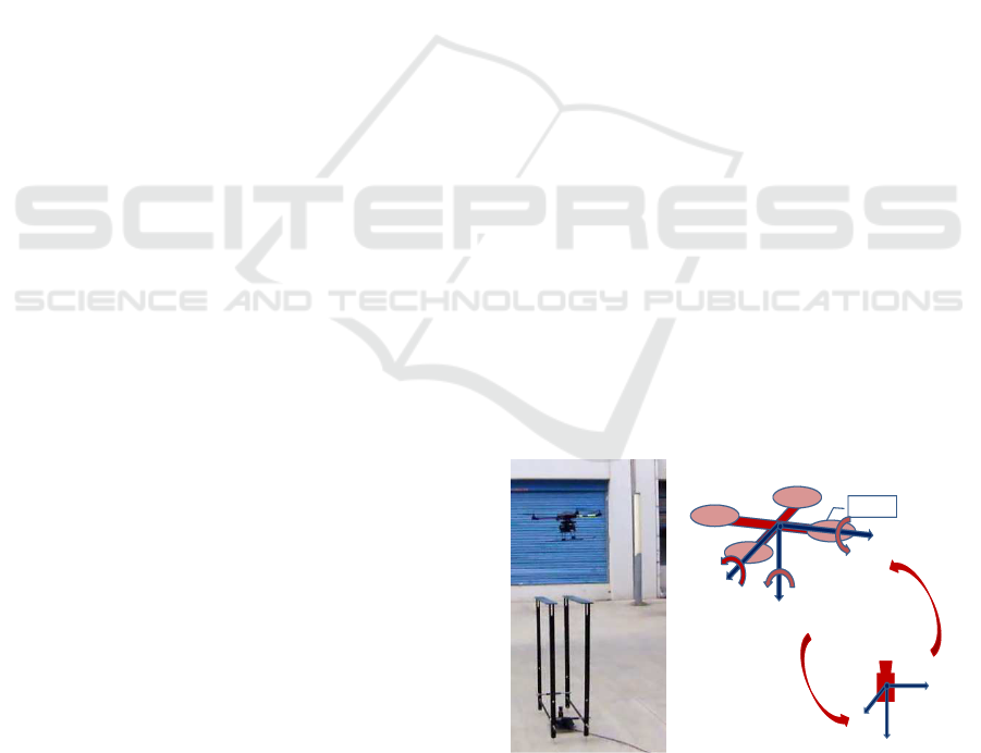
tem for the quadrotor. The motivation of our work is
to present an external vision based robust pose estima-
tion system for a quadrotor in outdoor environments
(see Figure 1). This system could provide us with ap-
proximate ground-truth pose of the quadrotor, which
could be used to evaluate experimental results and im-
prove algorithms. It can also be used for autonomous
take-off or landing of a quadrotor. Considering oc-
clusion or poor tracking results, most external vision
based systems for the quadrotor do not mention this
and can not get right pose results. We propose the
novel robust pose estimation algorithms to solve this.
Nowadays, most of external vision based systems
work indoors. Approaches (Altug et al., 2003; Achte-
lik et al., 2009; Breitenmoser et al., 2011) placed
some colored blobs or LED markers on the quadrotor
to estimate the pose. Colored blobs or LEDs may not
be well detected and tracked in outdoor environments.
(How et al., 2008; Ahrens et al., 2009; Abeywardena
et al., 2013) used the VICON(a motion capture sys-
tem) for observing the quadrotor indoors. These sys-
Quadrotor
( )
Q
X Roll
( )
Q
Y Pitch
( )
Q
Z Yaw
Nose
Camera
w
X
w
Y
w
Z
Figure 1: The robust pose estimation system for a quadrotor.
tems were complex and expensive.
Systems designed for outdoor environments are
quite rare. (Ha and Lee, 2013) used an unmanned
ground vehicle to track the quadrotor. (Wendel
et al., 2011; Lim et al., 2012) used results of of-
fline SFM(structure from motion) as ground truth and
could not perform in real-time.
Meanwhile, these methods (Altug et al., 2003;
Achtelik et al., 2009; Breitenmoser et al., 2011) need
to detect all the blobs or LEDs rightly. When one or
more blobs are lost, these approaches could not get
right pose estimation results.
718
Zheng W., Zhou F. and Wang Z..
External Vision based Robust Pose Estimation System for a Quadrotor in Outdoor Environments.
DOI: 10.5220/0004906007180723
In Proceedings of the 3rd International Conference on Pattern Recognition Applications and Methods (ICPRAM-2014), pages 718-723
ISBN: 978-989-758-018-5
Copyright
c
2014 SCITEPRESS (Science and Technology Publications, Lda.)

In this paper, we detect the rotors of a quadro-
tor to get our reference points. This refers to the
PnP(Perspective-n-Point) problem. There are some
work for PnP problems (Gao et al., 2003; Dementhon
and Davis, 1995; Hu and Wu, 2002; Hartley and Zis-
serman, 2004). The minimal numbers of correspon-
dences to solve PnP problems is three. P4P problem
with coplanar points has unique solution.
Approaches (Quan and Lan, 1999; Ansar and
Daniilidis, 2003; Lepetit et al., 2008) presented lin-
ear non-iterative algorithms for PnP problems. (Lu
et al., 2000; Schweighofer and Pinz, 2006) presented
excellent iterative algorithms.
Recently, some significant works (Fraundorfer
et al., 2010; Kukelova et al., 2010) had been done for
PnP problems with IMUs.
The contribution of our work is mainly as follows.
We present an external vision based robust pose es-
timation system for a quadrotor in outdoor environ-
ments, while most systems work indoors. Only the
own features of the quadrotor are employed, while
most systems modify the architecture of the quadrotor
or add additional components such as LEDs. We pro-
pose the novel robust pose estimation algorithm. This
algorithm could get the accurate pose from all of the
four reference points with good detection or tracking
results. But we may only get two or three reference
points when dealing with occlusion or poor tracking
results. This moment, all of existing external vision
based systems for the quadrotor do not mention this
and can not get right pose results. Our algorithm has
solved this case and could get accurate pose estima-
tion results by making use of the IMU data.
2 OUR WORK
2.1 The Own Features of the Quadrotor
One main character of our approach is that we only
use the own features of the quadrotor. We wish that
this method is simple, effective and more general. In
real experiments outdoors, it is difficult to observe
colored blobs, LED markers or appearance modifica-
tion. The quadrotor’s own features could provide us
with enough information for pose estimation and are
more reliable than approaches using colored markers.
2.2 Preliminary Position
Background difference and mean-shift are used for
detection and tracking. A brief illustration could be
seen in Figure 2. The coordinate position of the
quadrotor’s center is denoted by (x
q
,y
q
) in pixel. The
(a)
(b) (c)
Figure 2: A brief introduction of detection and tracking.
center of CCD sensor is seen as the origin of world
coordinate system. The real positions of a quadrotor
are:
Z
q
= D· f
d, (1)
X
q
= Z
q
· ˜x
q
/ f, Y
q
= Z
q
· ˜y
q
/ f, (2)
where f is the focal length and Z
q
,X
q
,Y
q
are real pre-
liminary position of the quadrotor. Here ˜x
q
and ˜y
q
are undistorted pixel coordinates. The D is the real
wingspan of the quadrotor, and d is undistorted pixel
distance of the wingspan in image. From Equation 2,
some results can be obtained:
X
q
= k·Y
q
or ˜x
q
= k· ˜y
q
, (3)
where k is scaling factor. When the intrinsic parame-
ters of the camera are measured accurately,the scaling
factor k could achieve a quite high accuracy.
2.3 Robust Pose Estimation
A simple illustration of the relative pose relationship
between the camera and the quadrotor could be seen
in Figure 1. Here Roll, Pitch and Yaw denote the ro-
tation about X
Q
, Y
Q
and Z
Q
axis.
2.3.1 Different Observed Situations
When occlusion or bad observing results occur,not all
of rotors are observed. The pose estimation problems
of a quadrotor could be divided into four different sit-
uations (see Figure 3).
(1): All of four rotors are observed exactly (see
Figure 3 a b c).
(2): Three rotors are observed (see Figure 3 d e f).
(3): Two rotors are observed (see Figure 3 g h i).
(4): Fewer than two rotors are observed.
For these different situations, the last situation
could not be solved currently. We mainly solve the
former three situations. Most of current external vi-
sion based pose estimation systems of the quadrotor
solve the first situation. And for the second and third
situations, all of other external vision based pose esti-
mation systems of the quadrotor do not mention this
ExternalVisionbasedRobustPoseEstimationSystemforaQuadrotorinOutdoorEnvironments
719
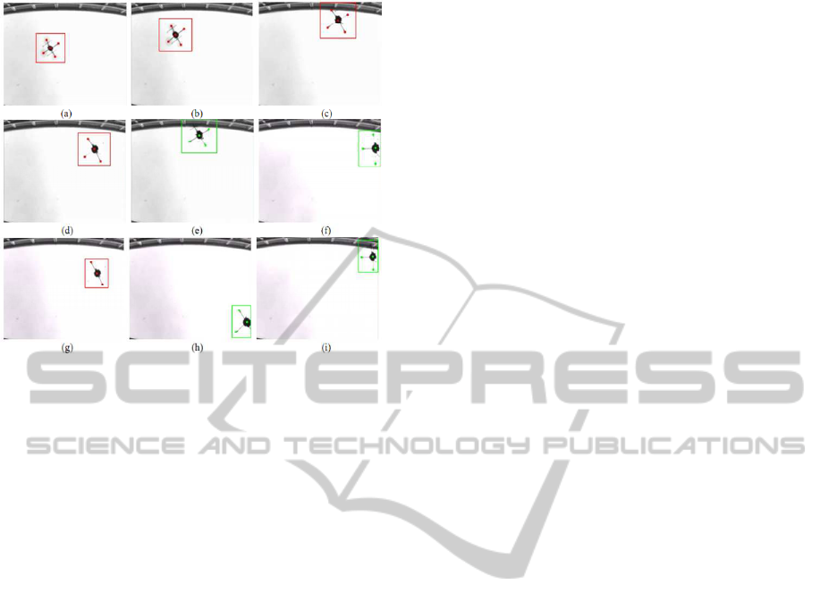
Figure 3: The different observed results of a quadrotor.
and can not get right pose results. In this paper, ac-
curate pose estimation results could be calculated by
making use of the IMU data.
2.3.2 Problem Formulation
The quadrotor could be seen as a fixed landmark when
flying at different positions. Here the quadrotor is the
object coordinate system. In this object coordinate
system, the 3D coordinates of centers of four rotors
are M
o
i
= (X
o
i
,Y
o
i
,Z
o
i
)
′
, i = 1,2,3,4. Centers of four
rotors could be seen as coplanar points. So we could
have M
o
i
= (X
o
i
,Y
o
i
,0)
′
, i = 1,2, 3, 4. The real values
of X
o
i
,Y
o
i
could be measured accurately in advance.
Their corresponding coordinates in camera coordinate
system are M
c
i
= (X
c
i
,Y
c
i
,Z
c
i
)
′
, i = 1, 2,3,4. We have
the relationship:
M
c
i
= R· M
o
i
+ T, (4)
where R = f(α,β,γ) and T = (t
x
,t
y
,t
z
)
′
are the rota-
tion matrix and the translation vector. The centers of
four rotors are expressed in the normalized image co-
ordinate system as m
i
= (u
i
,v
i
,1)
′
, i = 1,2,3, 4, which
are the projection of M
c
i
= (X
c
i
,Y
c
i
,Z
c
i
)
′
, i = 1,2,3,4.
The intrinsic parameters of the camera are known. We
have relationship:
m
i
∝ M
c
i
= (R· M
o
i
+ T). (5)
2.3.3 EMRPP Algorithm for Four Rotors
When all of four rotors of a quadrotor are observed,
the quadrotor could be seen as a landmark. The land-
mark formed by rotors here is four coplanar points.
(Schweighofer and Pinz, 2006) proposed a ro-
bust pose estimation algorithm(RPP) for four copla-
nar points. RPP made use of object-space error func-
tion. It considered that the orthogonal projection of
M
c
i
on m
i
should be equal to M
c
i
itself. This fact was
shown as follows (Lu et al., 2000):
R· M
o
i
+ T = F
i
· (R· M
o
i
+ T), (6)
F
i
= m
i
m
i
′
m
i
′
m
i
, (7)
where F
i
is a projection operator, F
i
= F
i
′
and F
i
= F
i
2
.
The object-space error function (Lu et al., 2000) was:
E
os
=
n
∑
i=1
k(I − F
i
)(R· M
o
i
+ T)k
2
. (8)
Making use of the coplanar properties, RPP trans-
formed the Equations 5 and 8. Then
˜
E
os
only depends
on a rotation about the y-axis
˜
R
y
(
˜
β) and
˜
T:
˜m
i
∝ R
z
(
˜
γ)(
˜
R
y
(
˜
β) ·
˜
M
o
i
+
˜
T), (9)
˜
E
os
=
n
∑
i=1
||(I −
˜
F
i
)R
z
(
˜
γ)(
˜
R
y
(
˜
β) ·
˜
M
o
i
+
˜
T)||
2
, (10)
˜
T = (
˜
t
x
,
˜
t
y
,
˜
t
z
)
′
, (11)
where symbol ∼ above the variables denotes the
transformations of these variables.
Here we give the MRPP(modified RPP) algo-
rithm. In former section, we get the preliminary po-
sition of the quadrotor. From Equation 3, we could
get:
t
x
= k·t
y
. (12)
Then we put Equation 12 into Equations 5 and 8:
˜m
i
∝ R
z
(
˜
γ)(
˜
R
y
(
˜
β) ·
˜
M
o
i
+
ˆ
T), (13)
˜
E
os
=
n
∑
i=1
||(I −
˜
F
i
)R
z
(
˜
γ)(
˜
R
y
(
˜
β) ·
˜
M
o
i
+
ˆ
T)||
2
, (14)
ˆ
T = (
ˆ
k
ˆ
t
y
,
ˆ
t
y
,
ˆ
t
z
)
′
, (15)
where
ˆ
k is the transformation of k. By using the scal-
ing factor k, there are only two degrees of freedom in
ˆ
T here. Then
˜
E
os
only depends on a rotation about the
y-axis
˜
R
y
(
˜
β) and
ˆ
t
y
,
ˆ
t
z
.
As iterative algorithms, RPP and MRPP both need
the initial pose guess which affects the computation
time and the accuracy of results. (Lepetit et al., 2008)
proposed a non-iterative solution EPnP. It had better
accuracy and lower computational complexity than
other non-iterative approaches.
ICPRAM2014-InternationalConferenceonPatternRecognitionApplicationsandMethods
720

In order to get robust and accurate pose estima-
tion results, we present a newalgorithm EMRPP com-
bined by EPnP and our MRPP algorithms. We first
perform EPnP to get the initial pose estimation. Then
we make use of this initial value as the input of MRPP.
2.3.4 Three/Two Rotors Observed
When only three or two rotors of a quadrotor are ob-
served, we will make use of the IMU data to get the
accurate results. The IMU on the quadrotor could pro-
vide us with Roll and Pitch angles of the quadrotor.
The angular accuracy of Roll and Pitch angles is be-
low 0.5 degree. In general, the image data is later
from -5ms to 15ms than IMU data. For pose estima-
tion, we use the image data with the IMU data which
arrived at the computer 10ms before.
Here we modify the algorithm of (Kukelova et al.,
2010). In our work, the rotation matrix R is:
R = R
z
R
y
R
x
, (16)
where R
z
,R
y
and R
x
are separately the rotation matrix
for the Yaw, Pitch and Roll axis. And R
y
is:
R
z
=
cosα −sinα 0
sinα cosα 0
0 0 1
, (17)
From the data returned by the IMU, we can get
the values of R
x
and R
y
. So the only one unknown
parameter of the rotation matrix R is the rotation angle
α around the Yaw axis. Equation 5 would be:
λm
i
= [R
z
(α)R
y
R
x
|T] M
i
, (18)
where λ is the scaling factor. m
i
are normalized image
coordinates and M
i
are homogeneous coordinates. To
simplify the former equation, we use the substitution
q = tan(α/2). Then we could get:
(1+q
2
)R
z
(q) =
1− q
2
−2q 0
2q 1− q
2
0
0 0 1+ q
2
. (19)
So the equation 18 could be written as:
[m
i
]
×
[R
z
(q)R
y
R
x
|T] M
i
= 0, (20)
where [m
i
]
×
is the skew symmetric matrix of m
i
and
the rank of [m
i
]
×
is two. Equation 20 produces three
polynomial equations and only two are linearly inde-
pendent. From equation 3, we have t
x
= k·t
y
.
Employ this constraint in equation 20 and we get:
[m
i
]
×
[R
z
(q)R
y
R
x
|T(kt
y
,t
y
,t
z
)]M
i
= 0. (21)
In this case there are only three unknown variables
t
y
,t
z
,q. But there is variable q of degree two, the min-
imal number of point correspondences we need to get
unique pose estimation is two.
When three rotors are observed, we have six inde-
pendent polynomial equations. By using least squares
method, the pose estimation could be obtained. This
algorithm is named as IMU+3P. If two rotors are ob-
served, there would be just four independent polyno-
mial equations. So we will get unique solution of pose
estimation. This algorithm is named as IMU+2P.
3 EXPERIMENTS AND RESULTS
In real experiments, we compare our algorithms with
some state-of-the-art or classics algorithms, such as
GAO (Gao et al., 2003), LHM (Lu et al., 2000), RPP
(Schweighofer and Pinz, 2006), and EPnP (Lepetit
et al., 2008).
We have performed our algorithms in real outdoor
environments. Here we select the Z
q
of translation
results of RPP as true height. Then this true value
Z
q
is used in equation 2 to get the true X
q
and Y
q
.
The real rotation angles are obtained from IMU data
and electronic compass. The translation error is the
angle between the estimated translation direction and
the ground-truth direction. The rotation error is the
smallest angle of rotation to bring the estimated rota-
tion to the ground-truth rotation.
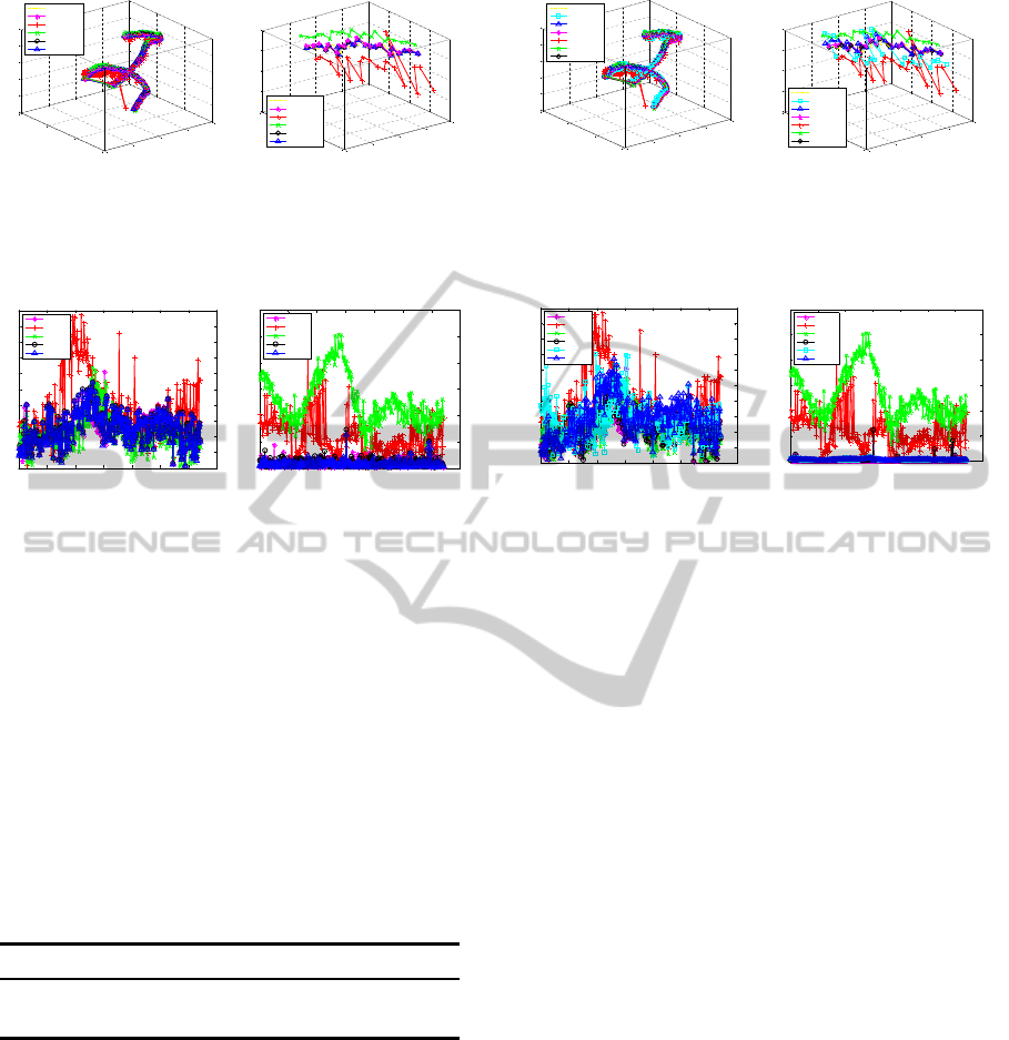
3.1 Four Rotors Observed
3.1.1 Results of Real Experiments
When all of the four rotors are observed, the results of
real experiments are shows in Figure 4. The ground-
truth is figured in yellow. EMRPP and RPP have bet-
ter robust pose results in our real experiments. The
results of RPP are close to our EMRPP. In general,
EMRPP has better performance than RPP. In order to
show the details of results clearly, results of 20 se-
quential frames are showed in Figure 4b.
3.1.2 Pose Error in Real Experiment
Figure 5a shows the translation error in real exper-
iments. EMRPP, LHM and RPP have better robust
translation results. The translation errors of EMRPP
are slightly lower than RPP. Figure 5b shows the rota-
tion error of these algorithms in real experiments. The
results of EPnP and GAO are bad. EMRPP, LHM and
RPP have good rotation accuracy. EMRPP has best
rotation accuracy and robust results here.
ExternalVisionbasedRobustPoseEstimationSystemforaQuadrotorinOutdoorEnvironments
721
-1500
-1000
-500
0
500
-500
0
500
1000
2600
2800
3000
3200
3400
3600
X position in mm
Real Experiment
Y position in mm
Z position in mm
Ground-Truth
LHM
GAO
EPnP
RPP
EMRPP
-650
-600
-550
-500
-450
300
350
400
450
500
3000
3050
3100
3150
3200
X position in mm
Real Experiment
Y position in mm
Z position in mm
Ground-Truth
LHM
GAO
EPnP
RPP
EMRPP
(a) (b)
Figure 4: The results of real experiments when four rotors
are observed. The entire results are showed in (a), while
part of results are showed in (b).
0 50 100 150 200 250 300 350
0
0.05
0.1
0.15
0.2
0.25
0.3
0.35
0.4
0.45
0.5
Sequential frames
Translation error in degrees
Translation error in Real Experiment
LHM
GAO
EPnP
RPP
EMRPP
0 50 100 150 200 250 300 350
0
10
20
30
40
50
60
Sequential frames
Rotation error in degrees
Rotation error in Real Experiment
LHM
GAO
EPnP
RPP
EMRPP
(a) (b)
Figure 5: The translation error and the rotation error.
3.1.3 Discussion
Algorithms are written in C/C++ and tested in a note-
book which has two i3 CPUs and 4G memory. The
computation time of these algorithms can be seen in
Table 1. GAO and EPnP algorithms perform fast, but
they have low accuracy. EMRPP and RPP have quite
good accuracy of pose estimation. Both computation
time of EMRPP and RPP are below 2ms and certainly
meet the request of real-time applications. In fact, our
EMRPP usually has higher accuracy than RPP and
performs 10% faster than RPP.
Table 1: Computation time in microsecond (µs).
LHM GAO EPnP RPP EMRPP
Mean 544 30 109 1739 1592
Median 508 28 99 1613 1484
Our EMRPP is combined by EPnP and MRPP.
The first step of EMRPP could get accurate initial es-
timation of pose. A good initial estimation speeds up
the following iterative section of EMRPP and get ro-
bust and accurate pose results. Because the EPnP is
a fast non-iterative algorithm and the good initial es-
timation would speed up the MRPP algorithm. So
EMRPP is faster and has higher accuracy than RPP.
-1500
-1000
-500
0
500
-500
0
500
1000
2600
2800
3000
3200
3400
3600
X position in mm
Real Experiment
Y position in mm
Z position in mm
Ground-Truth
IMU+2P
IMU+3P
LHM
GAO
EPnP
RPP
-650
-600
-550
-500
-450
300
350
400
450
500
3000
3050
3100
3150
3200
X position in mm
Real Experiment
Y position in mm
Z position in mm
Ground-Truth
IMU+2P
IMU+3P
LHM
GAO
EPnP
RPP
(a) (b)
Figure 6: The results of real experiments when using three
or two rotors. The entire results are showed in (a). Part of
results are showed in (b).
0 50 100 150 200 250 300 350
0
0.05
0.1
0.15
0.2
0.25
0.3
0.35
0.4
0.45
0.5
Sequential frames
Translation error in degrees
Translation error in Real Experiment
LHM
GAO
EPnP
RPP
IMU+2P
IMU+3P
0 50 100 150 200 250 300 350
0
10
20
30
40
50
60
Sequential frames
Rotation error in degrees
Rotation error in Real Experiment
LHM
GAO
EPnP
RPP
IMU+2P
IMU+3P
(a) (b)
Figure 7: The translation error and the rotation error.
3.2 Three/Two Rotors Observed
3.2.1 Results of Real Experiments
In order to compare IMU+2P, IMU+3P with other al-
gorithms, we also operate LHM, GAO, EPnP and RPP
which use all of four point correspondences. Figure
6 shows the results of real experiments. The results
of IMU+2P are better than GAO and similar to EPnP.
IMU+3P, LHM and RPP have good and similar re-
sults. The accuracy of IMU+3P is quite good and
meets the requirement of real applications.
3.2.2 Pose Error in Real Experiment
Figure 7a shows the translation error in real exper-
iments. Here the translation accuracy of IMU+2P
is slightly lower than LHM, RPP. IMU+3P has bet-
ter translation results than IMU+2P. The accuracy of
IMU+2P and IMU+3P is enough for real experiments.
Figure 7b shows the rotation error in real experiment.
IMU+2P and IMU+3P have the best rotation accuracy
in these algorithms.
3.2.3 Discussion
IMU+3P has both good translation and rotation ac-
curacy. IMU+2P has lower translation accuracy and
higher rotation accuracy than GAO, LHM, EPnP and
RPP. Usually IMU+2P has higher rotation accuracy
than IMU+3P. This could be explained. The number
ICPRAM2014-InternationalConferenceonPatternRecognitionApplicationsandMethods
722

of point correspondences is related to translation esti-
mation. When number of points is in a certain range,
the more points we use, the higher translation accu-
racy we will have. IMU+3P has higher translation
accuracy than IMU+2P which only applies two cor-
respondences. And the translation error of IMU+2P
and IMU+3P is usually higher than EPnP, LHM and
RPP. For the rotation error, roll and pitch angles could
be obtained from IMU. Usually IMU has a quite high
accuracy, so IMU+2P and IMU+3P have higher rota-
tion accuracy than GAO, LHM, EPnP and RPP. When
the number of point correspondences is small and not
large, the more point correspondencesmay disturb the
accuracy of rotation calculating especially that there
are high accuracy IMU data. So IMU+3P has lower
rotation accuracy than IMU+2P.
4 CONCLUSIONS
In this paper, we present an external vision based ro-
bust pose estimation system for a quadrotor in out-
door environments. We only use the own features
of the quadrotor. When four rotors are observed,
we present the EMRPP algorithm which has higher
accuracy and less computation time than RPP algo-
rithm. When only three or two rotors are observed, we
present IMU+3P or IMU+2P algorithm which could
also get right pose estimation results. We have imple-
mented real experiments using our system in outdoor
environments. This system could provide us with ap-
proximate ground truth of pose for a flying quadrotor.
Our pose estimation system could perform accurately
and robustly in real time.
ACKNOWLEDGEMENTS
This work is supported by the National Sci-
ence and Technology Major Project of the Min-
istry of Science and Technology of China: ITER
(No.2012GB102007).
REFERENCES
Abeywardena, D., Wang, Z., Kodagoda, S., and Dis-
sanayake, G. (2013). Visual-inertial fusion for quadro-
tor micro air vehicles with improved scale observabil-
ity. In ICRA, pages 3148–3153.
Achtelik, M., Zhang, T., Kuhnlenz, K., and Buss, M.
(2009). Viusal tracking and control of a quadcopter
using a stereo camera system and inertial sensors. In
ICMA, pages 2863–2869.
Ahrens, S., Levine, D., Andrews, G., and How, J. P. (2009).
Vision-based guidance and control of a hovering ve-
hicle in unknown, gps-denied environments. In ICRA,
pages 2643–2648.
Altug, E., Ostrowski, J. P., and Taylor, C. J. (2003). Quadro-
tor control using dual camera visual feedback. In
ICRA, pages 4294–4299.
Ansar, A. and Daniilidis, K. (2003). Linear pose estimation
from points or lines. In PAMI, 25:578–589.
Breitenmoser, A., Kneip, L., and Siegwart, R. (2011). A
monocular vision-based system for 6d relative robot
localization. In IROS, pages 79–85.
Dementhon, D. F. and Davis, L. S. (1995). Model-based
object pose in 25 lines of code. In IJCV, 15:123–141.
Fraundorfer, F., Transkanen, P., and Pollefeys, M. (2010).
A minimal case solution to the calibrated relative pose
problem for the case of two known orientation angles.
In ECCV, pages 269–282.
Gao, X.-S., Hou, X.-R., Tang, J., and Cheng, H.-F. (2003).
Complete solution classification for the perspective-
three-point problem. In PAMI, 25:930–943.
Ha, C. and Lee, D. (2013). Vision-based teleoperation of
unmanned aerial and ground vehicles. In ICRA, pages
1465–1470.
Hartley, R. and Zisserman, A. (2004). Multiple View Geom-
etry in Computer Vision (Second Edition). Cambridge
University Press.
How, J. P., Bethke, B., Frank, A., Dale, D., and Vian, J.
(2008). Real-time indoor autonomous vehicle test en-
vironment. IEEE Control Systems Magazine, 28:51–
64.
Hu, Z. and Wu, F. (2002). A note on the number of solutions
of the noncoplanar p4p problem. In PAMI, 24:550–
555.
Kukelova, Z., Bujnak, M., and Pajdla, T. (2010). Closed-
form solutions to the minimal absolute pose problems
with known vertical direction. In ACCV, pages 216–
229.
Lepetit, V., Moreno-Noguer, F., and Fua, P. (2008). Epnp:
Accurate non-iterative o(n) solution to the pnp prob-
lem. In IJCV, 81:151–166.
Lim, H., Sinha, S. N., Cohen, M. F., and Uyttendaele,
M. (2012). Real-time image-based 6-dof localization
in large-scale environments. In CVPR, pages 1043–
1050.
Lu, C., Hager, G., and Mjolsness, E. (2000). Fast and glob-
ally convergent pose estimation from video images. In
PAMI, 22:610–622.
Quan, L. and Lan, Z. (1999). Linear n-point camera pose
determination. In PAMI, 21:774–780.
Schweighofer, G. and Pinz, A. (2006). Robust pose estima-
tion from a planar target. In PAMI, 28:2024–2030.
Wendel, A., Irschara, A., and Bischof, H. (2011). Natural
landmark-based monocular localization for mavs. In
ICRA, pages 5792–5799.
ExternalVisionbasedRobustPoseEstimationSystemforaQuadrotorinOutdoorEnvironments
723
