
A New Integration Method for Mounting and in vivo
Handling of Sub-mm Flexible Cuff Electrode
Fábio Rodrigues
1,2
and Paulo Mendes
1
1
Centro Algoritmi, University of Minho, Guimarães, Portugal
2
DIMES/ECTM, Delft University of Technology, Delft, The Netherlands
Keywords: Neural Stimulation, Cuff Electrode, Mounting, Polyimide, PDMS.
Abstract: Electrical stimulation of peripheral nerves is commonly used in both research and clinical fields. Cuff
electrodes are one possible interface between nerves and the stimulation microsystem. Among cuff
electrodes, flexible, polyimide-based devices have been demonstrating good and consistent results for the
past 15 years. Regarding mounting and mechanical stability of flexible electrodes for in vivo trials,
improvements are still due. A new concept aiming at the integration of polyimide-based devices in an elastic
handling structure was developed. By taking advantage of PDMS elasticity and moulding, this new
integration method provides surgeons with the ability to move and to rotate the cuff minimizing nerve-
electrode contact and, consequently, nerve damages. A 9 parts stainless steel mould was designed and
fabricated to allow integration of polyimide electrode arrays together with the PDMS mounting structure
and a print circuit board. Furthermore, with the fabricated mould it is possible to achieve a final cylindrical
channel with diameter of 800 µm, as well as handling strips to open and close the cuff.
1 INTRODUCTION
Electrodes are a key component in neural
engineering applications, being used as both
actuators and sensors, i.e. to excite neural tissue by
electrical stimulation or to record bioelectrical
signals from it. Therefore, implantable electrodes
work as interfaces between neural prostheses and the
biological tissue. Among others, potential
applications of implantable electrodes for neural
electrical stimulation range from restoration of
walking (Gustafson et al., 2010) to vagal nerve
stimulation (e.g., epilepsy treatment or heart rate
control) (Connor et al, 2012)and bladder
management in incontinence (Rijkhoff et al, 1997).
Geometrical configuration and dimensions of
electrodes are strongly dependent on the size and
morphology of target nerves. For cylindrical shaped
nerves (e.g., sciatic nerve, vagus nerve) electrodes
made of flexible substrates are a good solution
because they can be wrapped around the nerve.
Usually, this is made by means of cuff electrodes
(Veraart et al, 1993). Cuff electrode diameters range
from hundreds of micrometers (Rodrigues et al,
2012) to few milimeters. During the last two
decades, improvements in the variety and in the
complexity of electrodes for neural stimulation have
provided new solutions in new applications fields
(e.g., vagus nerve stimulation in epislepsy treatment
(Englot et al., 2011, or the FINE electrode for
walking restoration (Schiefer et al., 2008). Many of
these clinical improvements were enabled through
the development of micromachining technologies.
Polyimide-based electrodes have been
demonstrating good and consistent results for the
past 15 years. Polyimides have become an important
and widespread used material for flexible electrodes
due to its good adhesion to metals, long lifetime and
low rate of water retention. Electrodes made of
polyimide usually consist of a thin-film
metallization sandwiched between two layers of
polymer. Thin, uniform layers of polymer are
achieved by means of pouring polyimide on the
substrate followed by spinning. Therefore, the total
thickness of a flexible, polyimide-based electrode is
lower than 30 μm and in vivo handling conditions
require a protective layer between the polyimide and
the biological surrounding tissues.
Biomedical microsystems must fulfil different
requirements for acute and chronic implantation.
When using cuff electrodes for electrical stimulation
of peripheral nerves, three of these requirements are:
265
Rodrigues F. and Mendes P..
A New Integration Method for Mounting and in vivo Handling of Sub-mm Flexible Cuff Electrode.
DOI: 10.5220/0004914602650270
In Proceedings of the International Conference on Biomedical Electronics and Devices (BIODEVICES-2014), pages 265-270
ISBN: 978-989-758-013-0
Copyright
c
2014 SCITEPRESS (Science and Technology Publications, Lda.)
1) a reliable method for cuff opening and closing
(without damaging the nerve), 2) a mechanical, thus
electrical, stable microsystem and 3) to protect the
thin polyimide layers from potential damages when
in vivo. In the present work, we these three practical
challenges were addressed by designing and
fabricating an elastic mounting structure. The
fabricated mould with which it is possible to achieve
the embedment of flexible electrode, silicon chip
and the print circuit board (PCB) is presented. The
used silicone is PDMS, a very used material in
microfluidics and bio-MEMS applications, because
it is easy to mould and biocompatible.
2 MATERIALS AND METHODS
2.1 Mounting Structure Design and
Materials
Our goal is to build a system to allow integration of
a flexible cuff electrode in an elastic mounting
structure, thus providing surgeons and physicians
with a tool to rotate or/and to move the electrode
array along the nerve. The target nerve in our
research is the rat vagus nerve – a cylindrical shaped
nerve with a diameter of approximately 600 μm.
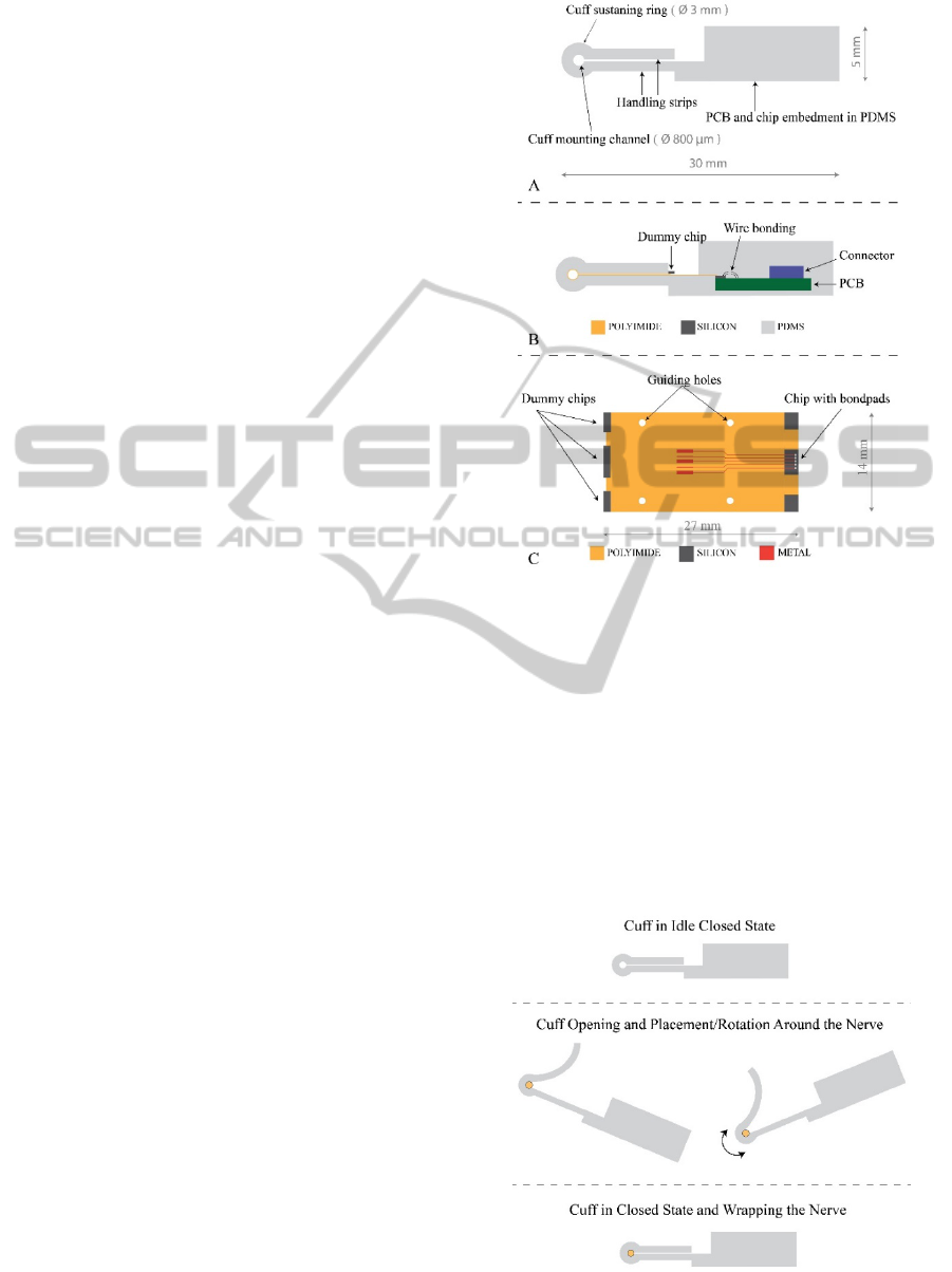
Fig. 1 shows a schematic of the proposed
mounting structure plus schematic of integrated
system and a 2-D view of the flexible electrode. In
order to have enough room for the nerve a central
channel with a diameter of 800 μm is designed – the
cuff mounting channel. A cuff sustaining ring is
designed with 3 mm in order to have a minimum
amount of elastic material around the flexible
polyimide. It keeps the cuff closed during
implantation but also allows an easy opening.
Handling strips allow positional adjustments during
in vivo experiments, as shown in fig. 2. Re-
positioning of electrode array around the nerve can
be done by using tweezers for cuff opening. As the
handling strips are released, cuff goes back to its
original closing position, taking advantage of PDMS
elasticity. Besides integration of polyimide
electrode, the mounting structure was also designed
to protect wire bonding (from chip to PCB), to
integrate PCB and a connector (fig. 1B). A good
alignment between the micro-fabricated electrode
and the mounting structure is crucial, as the
electrode array is designed to be wrapped around the
cuff mounting channel. To facilitate the alignment
between electrode and mounting structure, 4 guiding
holes (1.05 mm in diameter each) were included in
the polyimide layer (fig. 1C).
Figure 1: A. Cross section view of elastic mounting
structure. B. Schematic of integrated microsystem. C. Top
view of polyimide electrode array.
To fabricate the elastic mounting structure, a
mould consisting of 9 main parts was designed and
fabricated. Then, polydimethylsiloxane (PDMS,
Sylgard 184, Dow Corning) was poured and cured
inside the mould. Sylgard 184 consists of two parts:
elastomer and curing agent. These two parts were
mixed at 10:1 ratio (10 parts of elastomer - 1 part of
curing agent), very well mixed and degassed. For the
curing of PDMS, a short period of 30 min at 65 ºC
was used.
Figure 2: Operational states of the elastic mounting
structure.
BIODEVICES2014-InternationalConferenceonBiomedicalElectronicsandDevices
266
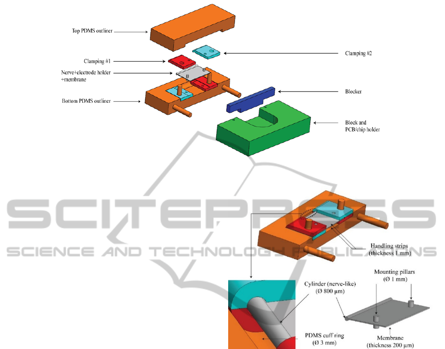
Figure 3: Exploded view of designed mould parts. Identification of each part by a label name.
2.2 Mould Design and Material
To realize the elastic mounting structure using
PDMS, a mould composed of 9 different parts was
designed using Solidworks 2013. Fig. 3 shows an
exploded view of the 9 parts of the mould. The
design was made in order to achieve the following
characteristics: 1) leak tight, 2) easy
assembly/disassembly and 3) straightforward
mounting of flexible electrode using the 4 guiding
holes. Due to PDMS viscosity in its uncured stage,
gaps higher than 20 µm between mating parts can
origin a leak. So then, tolerances were kept as high
as 10 µm. Few pillars were introduced to align
mould parts and 2 mounting pillars (1 mm in
diameter) were designed specifically for the
alignment of the flexible electrode, by using the 4
guiding holes. These 2 mounting pillars are the
smaller ones in the clamping parts (fig. 4).
Clamping parts fix the flexible electrode
wrapped around the ‘Nerve+electrode
holder+membrane’ part. This clamping mechanism
is responsible for alignment of flexible electrode in
the mounting structure.
Thickness of handling strips (1 mm) is given by
the thickness of clamping parts, as shown in fig. 4
and shaping of the cuff sustaining ring is given by
circular grooves in Top and Bottom PDMS outliner
parts. PDMS moulded by ‘Block and PCB/chip
holder’ part sustains the PCB and protects the chip
and the wire bonding area.
Stainless steel was chosen as material for the
moulding fabrication because of its high stiffness
(which reduces risks of breakage during cleaning)
and also because it is easy to clean by acetone and
isopropanol.
‘Nerve+electrode holder+membrane’ part is
composed by 2 independent parts: 1) a 200 µm sheet
Figure 4: Close-up of the clamping mechanism to mount
the flexible electrode.
of stainless steel with holes made by electrical
discharge machine (EDM): membrane and 2) a
cylinder with diameter of 800 µm coupled to the
membrane. These two parts are coupled together by
a longitudinal groove all along the cylinder, where
the membrane mates. This groove is also made by
EDM using a wire of 100 µm in diameter.
The mounting pillars are not solder to the
membrane. Also the grooves in the clamping parts
were made by EDM. All the other parts were made
by normal milling machines.
Fig. 5 depicts the final assembly of the mould.
All parts mate together. PDMS can be poured inside,
before adding the ‘Top PDMS outliner’ part, to
check for possible air bubbles. And it is also be
poured after mating all parts together, to make sure
that silicon, wire bonding and PCB are protected.
ANewIntegrationMethodforMountingandinvivoHandlingofSub-mmFlexibleCuffElectrode
267
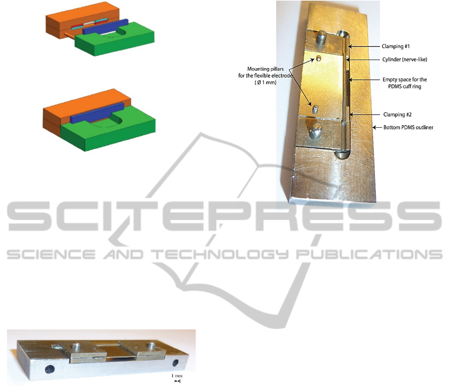
Figure 5: Final assembly of mould.
3 RESULTS
Some of fabricated parts are shown in fig. 6 and
fig. 7. In fig. 6 it is emphasized the 200 µm thick
membrane sandwiched in between the 4 clamping
parts. Fitting pillars to mate different parts are also
visible as well as the simmetry of the entire mould,
which is import to achieve a stable and working
mounting structure. Also, low roughness of the
fabricated stainless steel parts is important to avoid
air bubbles inside PDMS.
Figure 6: Some of the fabricated parts. Membrane is 200
µm.
In fig. 7, ‘Bottom PDMS outliner’, 2 clamping
parts and the ‘Nerve+electrode holder+membrane’
part are shown. The cylinder of the former part is
well aligned with the grooves in the clamping parts.
Also the cylinder (nerve-like) is well aligned with
the grooves in the ‘Bottom PDMS outliner’, which
contributes for a good alignment of the flexible
electrode with PDMS cuff ring.
The 200 µm thick membrane could be very well
fitted in the mounting pillars, which also contributed
for a good alignment. In our first trials, PDMS was
poured before placing the ‘Nerve+electrode
holder+membrane’ which led to less air bubbles in
the final moulded mounting structure.
In fig. 8, the part ‘Nerve+electrode
holder+membrane’ is shown in detail. To prevent
damages (like bending) to the membrane it has to be
handled by tweezers. And also to prevent the stick
Figure 7: Alignment of cylinder (nerve-like) with the
clamping parts and with the groove for the PDMS cuff
ring.
and the membrane to detach from each other.
After few moulding iterations, we have not seen
any signs of reactions between the mould parts and
the PDMS. We also report that, acetone and
isopropanol are good cleaning agents for the
stainless steel parts after PDMS moulding. However,
if between moulding iterations cleaning is not well
done in all small features, some residues might
prejudice the next procedure.
3.1 Elastic Mounting Structure
In fig. 9 it presented one mounting structure after
being moulded and removed from the mould. It is in
the closed idle state, so the two handling strips are
closed and the cuff channel can be seen in the
bottom part of the figure. Total width is about the
diameter of a euro-cent coin, while the length is
slighty bigger.
In fig. 11, it is shown a cuff opening technique
by using a tweezer. It is possible to open the cuff
just by pulling the handling strip, so without using
high force. This is important to: 1) preserve, in a
future prototype, good adhesion between the flexible
polyimide electrode and the elastic mounting
structure and 2) cuff position around the nerve can
be adjusted without damaging the nerve.
Final moulded structure showed a good overal
mechanical stability and also a good opening and
closing procedures due to PDMS elasticity after
being cured.
BIODEVICES2014-InternationalConferenceonBiomedicalElectronicsandDevices
268
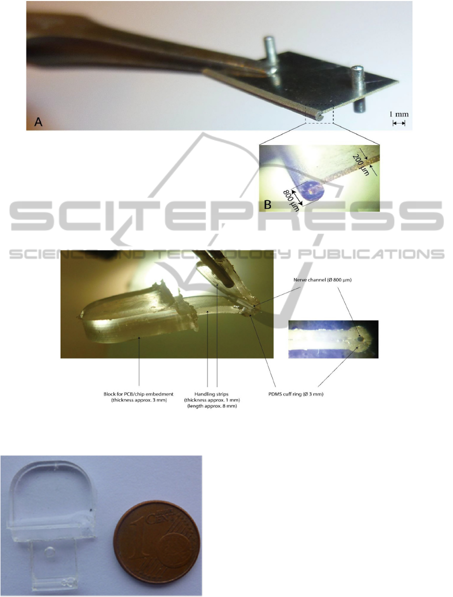
Figure 8: A. Close up view of the ‘Nerve+electrode holder+membrane’ part. B. Microscopic image of the slot made by
EDM to join membrane and stick together.
Figure 10: Left: Elastic mounting structure in its open state. Right: close up of the nerve (cuff) channel when the structure is
in its closed state.
Figure 9: Moulded mounting structure (without integrated
flexible electrode and PCB).
4 CONCLUSIONS AND FUTURE
WORK
A mould made of stainless steel was fabricated. The
presented mould is used to realize an elastic
structure which is a useful tool for implantation of a
cuff electrode around a nerve. Gometrical features of
the elastic structure were based on anatomical and
surgical constraints faced during in vivo tests in the
rat vagus nerve.
The integration of a flexible electrode in the
moulding step is under study. The final goal is to
achieve a fully embedded system for electrical
stimulation of the rat vagus nerve.
ANewIntegrationMethodforMountingandinvivoHandlingofSub-mmFlexibleCuffElectrode
269

ACKNOWLEDGEMENTS
This work was supported by the Portuguese
Foundation for Science and Technology
(SFRH/BD/62608/2009) and (PTDC/EEI-
TEL/2881/2012).
REFERENCES
Connor, D. E., Nixon, M., Nanda, A., & Guthikonda, B.
(2012). Vagal nerve stimulation for the treatment of
medically refractory epilepsy: a review of the current
literature. Neurosurgical focus, 32(3), E12.
doi:10.3171/2011.12.FOCUS11328.
Englot, D., Chang, E. & Auguste, K.. (2011). Vagus nerve
stimulation for epilepsy: a meta-analysis of efficacy
and predictors of response. Journal Neurosurgery,
115, 1248-1255.
Gustafson, K. J., Pinault, G. C. J., Neville, J. J., Jr, J. A.
D., Jean-claude, J., & Triolo, R. J. (2010). Fascicular
anatomy of human femoral nerve: implications for
neural prostheses using nerve cuff electrodes, 46(7),
973–984.
Rijkhoff, N., Hendrikx, L., van Kerrebroek, P., Debruyne,
F., & Wijkstra, H. (1997). Selective Detrusor
Activation by Electrical Stimulation of the Human
Sacral Nerve Roots. Artificial Organs, 21, 223–226.
Schiefer, M., Triolo, R., Tyler, D., (2008). A Model of
Selective Activation of the Femoral Nerve With a Flat
Interface Nerve Electrode for a Lower Extremity
Neuroprosthesis. IEEE Trans Neural Systems
Rehabilitation Eng., 16(2), 195-204.
doi:10.1109/TNSRE.2008.918425.
Rodrigues, F., Mimoun, B., Bartek, M., Dekker, R., &
Mendes, P. (2012). Flexible Multipolar Cuff
Microelectrode For FES Of Sacral Nerve Roots. In
Smart Machines – Neural Evolution. Banff, Canada:
IFESS .
Veraart, C., Grill, W. M., & Mortimer, J. T. (1993).
Selective control of muscle activation with a
multipolar nerve cuff electrode. IEEE transactions on
biomedical engineering, 40(7), 640–653.
doi:10.1109/10.237694.
BIODEVICES2014-InternationalConferenceonBiomedicalElectronicsandDevices
270
