
Design and Development of a Wireless Emergency Start and Stop
System for Robots
D. García, R. Barber and M. A. Salichs
RoboticsLab, University Carlos III of Madrid, Avda. de la Universidad 30, Leganes, Spain
Keywords: Safety Robotics, Emergency Stop, Microcontroller Application, Communication Modules.
Abstract: This paper develops a wireless communication system that connects robots with many remote control
devices used by many different users. The most important issue of this system is safety. To get high safety
level a quick and efficient communication system is required. The emergency system and its communication
system must work in parallel and independently of the main control of the robot. The robot must react to an
emergency signal, but as a previous step, it must make sure that the security system is enabled and it so
must also have some knowledge of how many remote control devices are related and if any of them has lost
the wireless connection. Besides all the research and design stage to develop the communication system, the
system has been implemented and tested. To build it, a microcontroller Arduino Fio and a radio frequency
module Xbee has been used. Finally, the system has been tested in order to characterize the communication
system, settling, connection time and the battery life.
1 INTRODUCTION
The Robotics world not only helps industry in
manufacturing processes but it also helps people in
their everyday life tasks or chores, for example a
vacuum robot or Maggie Robot (Gonzalez et al.,
2011), used as an experimental platform for this
work.
Although, these robots might look like harmless
and little hazardous, it must not be forgotten that
they are still machines. Some control must be taken
over these machines and also these machines, at any
given time must be halted or stopped (Morisawa, et
al., 2005). The reason for this is not only because
they can cause people physical damage, but also for
the robots own sake, just in case the robot loses
control and it can fall, crash or impact with another
object.
For this reason, in order for the robot to start
moving and to perform its scheduled tasks, it will be
necessary that someone has control over the robot,
especially in the training period. This way, a person
will be the one to turn the robot on and off
wirelessly.
To make Maggie work a two relay system must
be turned on. These two relays will be enabled
separately, each one independently. Therefore, the
robot will only move or perform its tasks when both
relays will be switched on.
The system also has a third relay which will stop
the robot when there is an emergency stop. The
activation of the emergency stop can be activated in
two different ways. The first one of them is that the
base, where the robot motors and batteries are
placed, will approach an object then this object will
be captured by proximity sensors enabling the
emergency stop. The second reason why the robot
could stop is that the user presses the emergency
push button of its remote control. This last system
works with an infrared transmitter, similar to the
remote control used for opening doors. These remote
control devices are not always 100% reliable, even
on many occasions it is necessary to point towards
the goal in order for the transmitted signal to be sent
correctly.
In this work the design and implementation of a
wireless activation and emergency stop system is
accomplished. This system works in a wireless
transmission medium that can control several robots,
using small microcontrollers and XBEE RF (Radio
Frequency) modules that will solve any connectivity
problem and that will make the robot control system
safer. For the emergency system design the
following specifications have been brought up:
- Mobile Robotics needs a 100% reliable
223
García D., Barber R. and Salichs M..
Design and Development of a Wireless Emergency Start and Stop System for Robots.
DOI: 10.5220/0004926602230230
In Proceedings of the 11th International Conference on Informatics in Control, Automation and Robotics (ICINCO-2014), pages 223-230
ISBN: 978-989-758-040-6
Copyright
c
2014 SCITEPRESS (Science and Technology Publications, Lda.)
emergency stop system.
- It must satisfy the manageability and usability
requirements for an autonomous vehicle in
terms of, the non-dependence of wires and its
size in order to integrate them in the robot.
- It must have a fast response.
- It must be a two-way communication system
that will allow having feedback information on
the real receipt of the emergency signal by
means of the robot.
- It must consider the possibility of having
different emergency emitters on a same robot
and even on different robots.
- As a result of these specifications, an
emergency system is presented that allows:
- Wireless emergency stop pushbutton switch
with two-way communication, endowing the
robot with more intelligence, integrating both at
hardware and software level with the robot’s
current architecture.
- A flexible system that allows several emergency
stop pushbutton switches and when used they
can be set up for each robot.
- Add while the robot is performing a task, new
emergency stop pushbutton switch and new
robots to the safety system.
The proposed system is based on the Xbee,
communication technology (Micea et al., 2012).
This system has been chosen over the traditional RF
technologies with conventional remote control
devices since it fulfils the proposed specifications.
This two-way communication and multipoint
technology minimizes the effects of loss of signal. It
can distinguish among different situations in which
the robot does not receive the signal or the
emergency system is out of batteries and other
common mobile robotics situations. XBee, in
addition, provides a two way protocol layer which
considerably makes easer its implementation,
allowing multi-point broadcast communication
(Laudon and Laudon, 2012).
2 SYSTEM DESCRIPTION
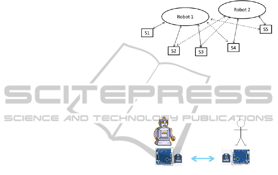
2.1 General Overview
The proposed system consists of a network of
emergency stop pushbutton switches and robots
interacting among themselves. The emergency stop
pushbutton switches will be integrated in the robot
working in parallel with other emergency systems
and with the robot’s own control system, although in
an independent way. Figure 1 shows the
implemented emergency management system
diagram. Each emergency stop pushbutton switch
can be connected to any robot, but not at the same
time. This is indicated by the dotted line.
Figure 1: Proposed emergency system.
2.3 System Parts
The full system, Figure 2, consists of two modules:
the emergency stop pushbutton switch and the on
board robot module, that is, the hosted module.
Figure 2: Architecture general scheme.
2.3.1 Emergency Stop Pushbutton Switch
The emergency stop pushbutton switch is the way by
which the user can control the robot. The user can
turn it on or off when needed and always in the
safest possible way, since this operation can be
performed wirelessly.
The system functions will be among others of
automatic response when a robot sends the
connection signal or the emergency stop pushbutton
switch refresh and the reading of the pushbuttons
position and signal sending to the system hosted in
the robot in order for the robot to change its state.
2.3.2 Device Hosted in the Robot
The device hosted in the robot forms the central
node of our communication system. This node will
act as coordinator, that is, it will get the packages
sent by all the system pushbutton switches and this
node will tell the following command or task the
system will perform.
Its main functions are the receipt of packages,
ICINCO2014-11thInternationalConferenceonInformaticsinControl,AutomationandRobotics
224
package analysis and action on the robot to operate it
or stop it, depending on the chosen pushbuttons on
the emergency pushbutton switch.
3 EMERGENCY PUSHBUTTON
SWITCH
The emergency pushbutton switch is the system
component by which the user interacts to create the
emergency signal on the robot. Therefore, it is the
element that links both the user and the robot. Its
design and communications system has been
implemented having this fact in mind.
3.1 Hardware Implementation
For the hardware design and implementation both
the required communication restrictions and
limitations of size have been considered. All the
hardware components must be located inside a
remote control device, that must fulfill the
ergonomic conditions allowing the way of holding it
and handling by the user. In Figure 3 a components
outline included in the hardware system is shown.
Figure 3: Emergency pushbutton switch electrical
schematic.
This device is based on an Arduino Fio
microcontroller (Arduino, 2013) with an Xbee radio
frequency module, as well as the robot. But, for this
implementation it can choose to which robot to be
connected, joining one or another network. The
microcontroller inputs and outputs are connected to
pushbuttons allowing operating with the emergency
stop pushbutton switch (three buttons to command
the emergency status) and two LEDs that show the
robot connection status.
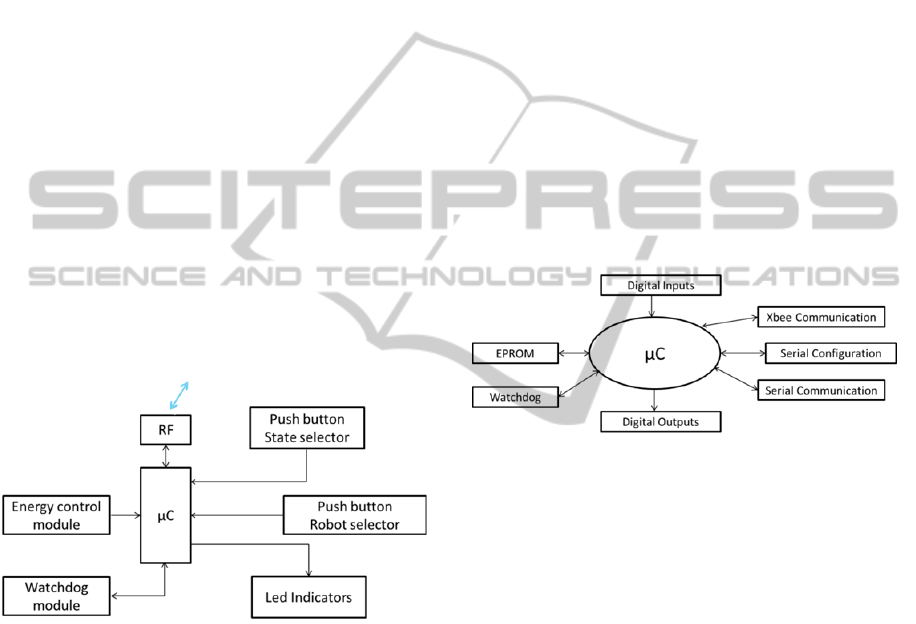
3.2 Software Implementation
Figure 4 shows the emergency stop pushbutton
switch software management diagram with the main
resources used by the microcontroller. The system
manages the use of analog and digital inputs and
outputs that enables the LEDs and it also uses the
Arduino FIO EEPROM memory to write and read
two important parameters for the system; one is the
PAN ID to which it will be connected and the other
parameter is the pushbutton switch address. This last
parameter is used to calculate the delay time of each
pushbutton switch, due to each pushbutton swith has
a unique address.
The rest of the resources used by this system are
relative to the Xbee RF module configuration, to the
communication with the robot and to a serial port
added for its configuration and testing.
The overall pushbutton switch operation consists
of waiting and listening until a message reaches the
robot. Once the package is received, the pushbutton
switch will answer the robot. The response package
will be different according to the buttons pressed in
the pushbutton switch.
Figure 4: Software resources used for the system hosted in
the pushbutton switch.
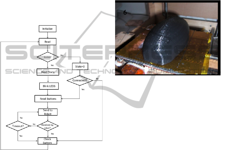
In Figure 5 the main pushbutton switch control flow
chart is shown. When the program is run the first
thing that has to be carried out is the microcontroller
and the Xbee module configuration (Foste, 2011).
To accomplish this task the data transmission
frequency will be specified, 57600 baud in this case,
and also the robot to be controlled will be chosen.
Additionally, in the setup the delay time this
pushbutton switch must have is calculated. Every
pushbutton switch has a different address and the
system will own up to 10 pushbutton switches and
directions will go from 2 to 9 and from A to B with a
representation in the hexadecimal system.
Once the system is configured, all the variables
involved in the main loop will be initialized. Next,
the reading an package management is carried out.
The received package is saved in a variable that
stores the pushbutton switch state, there are three
possibilities:
- State 0: There are two possibilities, one that no
robot has been yet detected, being in the search
state, so the green LED will slowly blink, or the
DesignandDevelopmentofaWirelessEmergencyStartandStopSystemforRobots
225
second possibility the refresh has not been yet
accomplished to tell which pushbutton switches
are connected, in this case the LED will quickly
blink.
- State 1: It means that a robot has been detected,
telling that it can connect to it. The green LED
will quickly blink. It is worth mentioning, if this
state is received it means that the robot is not
even moving.
- State 2: This states means that the robot in
addition to being connected is in motion, so
besides having the green LED blinking quickly,
the blue LED will be now turned on.
Figure 5: Main pushbutton switch control flow chart.
The next step is to read the pressed buttons from the
pushbutton switch and based on them, send an
answer or another. It is at this moment when the
delay time will be introduced, in which each
pushbutton switch will have different delays. For
this reason, we will ensure that the communication
between the pushbutton switch and the robot is
correct. Finally, the pushbutton switch state will be
sent as a reply to the connection or as a refresh to the
robot’s message.
3.3 Push Button Switch Design and
Construction
Last, the design and construction of the housing for
the emergency stop pushbutton switch is done. It has
been taken into account during this stage that it will
protect the microcontroller and the internal circuits
before any impact as well as its handling and
gripping by the end user.
The pushbutton switch has been made from ABS
plastic which is light, hard, strong and low cost. The
technique used in this work to create the pushbutton
switch housing is a 3D printer (Bassoli et al, 2007)
(Figure 6).
Figure 6: Emergency stop pushbutton switch final aspect.
4 SYSTEM HOSTED
IN THE ROBOT
The device placed in the robot forms the
communication system central node, so it will be its
own coordinator. It will see all the packages sent by
all the pushbutton switches in the system and it will
tell the following command or task the system will
perform.
Its main functions are the receipt of packages,
package analysis and action on the robot to operate it
or stop it, depending on the chosen pushbuttons on
the emergency pushbutton switch.
4.1 Hardware Implementation
The most important components in order for the
communication to be correctly established and that
each pushbutton switch will communicate with the
desired robot are: the Xbee RF module along with
the microcontroller that coordinates these
communications and that performs the operation that
modifies the robots’ state.
Each robot will create a different network, which
will be defined with a network ID different from a
robot to another (PAN ID). Robots will have a
unique address and pushbutton switches must
ICINCO2014-11thInternationalConferenceonInformaticsinControl,AutomationandRobotics
226
change the PAN ID according to the robot to which
they are connected. To make these adjustments in
the system hosted in the robot the Xbee RF modules
will need to configure using the X-CTU program.
On the other hand, this system should change the
robots state depending on the type of message
received, either by putting it into operation or by
stopping it. To do so, it will be necessary to act on
the relays that feed the robots’ motors. There are
three relays, one for the emergency stop and the
other two for the robot activation. Two activation
relays are used as a security matter, since a single
button could accidentally be pressed. For this reason
until both relays are not pressed at the same time the
robot will not start working.
To turn on these relays it will require that it is
done through a transistor, which will act as a switch,
since the current provided by the microcontroller
output pins is not enough for the relays to be set
(Moham et al., 2003)(Barrado and Lázaro,
2001)(Torres, 1994).
Figure 7 shows the scheme of the robot´s
activation and stop of the robot module.The Arduino
FIO microcontroller is represented in the middle of
the image. The LED indicators are connected to the
digital outputs of the Arduino to visualize that the
system placed in the robot has received a package
that would modify the robot’s state. The robots’
activation and stop relays are connected to the
Arduino. The EPROM module is used to store the
push button switch IDs. Xbee is used as RF module.
Figure 7: Robot´s system electrical schematic.
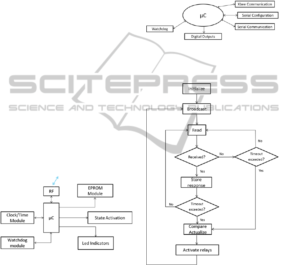
4.2 Software Implementation
Figure 8 shows a diagram of the resources used in
this system. In the centre stands the microcontroller
that will act on certain digital outputs. At the same
time it will also have connection with the XBee
module using the serial connector, for its initial
configuration, and a new SoftSerial module in order
to visualize communications behaviours, since the
serial connection included in the microcontroller is
in charge of the the XBbee RF module.
Figure 9 shows the flow chart of the main
management program of the system placed in the
robot. The first step is to adjust the configuration of
the inputs and outputs and of the XBEE RF module
parameters.
Figure 8: Software resources used for system placed in the
robot.
Then, a broadcast is sent (to all the pushbutton
switches), in order to connect to the robot.
Figure 9: General flow chart of the system placed in the
robot.
Once the broadcast is sent, the robot will wait for the
pushbutton switches answer. So the next step is to
read from the Xbee all the answers from each
pushbutton switch. Once the Xbee reading is carried
out, it now checks if it is the first time the system is
running to initialize the connections.
If it is not the first time the program is run, then
DesignandDevelopmentofaWirelessEmergencyStartandStopSystemforRobots
227
the number of connections that were in the previous
loop with the current one must be compared,
considering that new pushbutton switches could
have been connected. If connections are lost, the
robot will stop.
4.3 Design and Implementation of the
System Hosted in the Robot
Figure 10 shows the final system placed in the robot.
The microcontroller is mounted on a board, which
incorporates all the hardware components required
for the emergency stops management, the
communication modules and the robots’ power
supply connection.
Figure 10: Emergency module placed in the robot.
5 EXPERIMENTAL TEST
For the system validation several tests have been
carried out. These tests evaluate the connection
times and the battery life, which are the main factors
to determine the usability of the proposed system.
5.1 Establishing Time Two Way
Communication
This test measures the elapsed time since the emitter
sends a package until the receiver receives the
message and it send the confirmation message when
the package has correctly been received. This is very
important since it is the basis to estimate the time
that it takes for a pushbutton switch to connect, as
well as to allow to set the delay time so that another
pushbutton switch tries to connect. Also, it reports
the time that would take for a pushbutton switch to
send a signal to the robot to stop it. This signal
should arrive in the shortest time possible since it is
the most critical and important signal that the
pushbutton switch can send to the robot. The total
elapsed time between the activation of an emergency
button and the robot's response should depend on the
number of remote connected switches and must take
into account the results for the worst times.
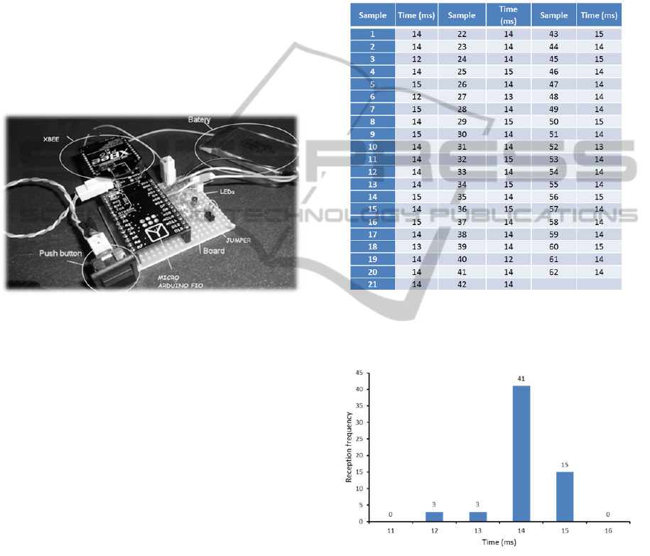
Table I shows the time results of the 62 samples
obtained, ranged from 12 to 15 milliseconds
Table 1: One package receipt time.
Performing a subsequent statistical analysis, along
with Figure 11 plot, the average data obtained is
14,079 milliseconds.
Figure 11: Bar chart of the mesaures obtained in the
package receipt time test.
In addition, other statisticians have been used as the
medium, and the result obtained is 14 milliseconds
and the mode that is also 14 milliseconds. With all
this data it can be concluded and estimated that the
time needed to send a package and to get the
confirmation message that the package has been
received, is 14 milliseconds.
ICINCO2014-11thInternationalConferenceonInformaticsinControl,AutomationandRobotics
228
5.2 Battery Characterization with
Pushbutton Switch Standard Use
This test will be performed with the use of a power
supply source with voltage regulation. The Arduino
Fio will use this power supply source. The voltage
will be decreased little by little until the
microcontroller stops working.
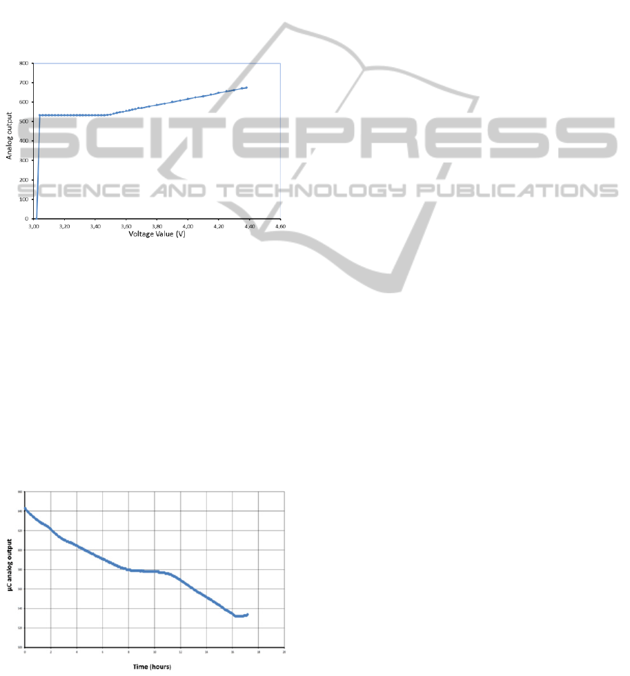
Samples are taken every 5 mV up to the 3.7 volts
and from the 3.7 V samples will be taken every 2
mV to have more data from the battery voltage and
thus characterize the system. Figure 12 shows the
results obtained.
Figure 12: Power supply voltage from source vs voltage
value obtained.
In the experiment the microcontroller does not read
voltage values from 3.02 V since it does not have
enough voltage to operate and a shutdown occurs. In
the range between 3.02 V and 3.7 V, which is the
voltage range where the pushbutton switch will
operate, the turning point of the microcontroller
voltage reading occurs, so from this voltage value on
it could not be tell apart whether the battery voltage
continues decreasing. For this reason, at a voltage
value of 3.48 V the low battery warning point will
be placed.
Finally, Figure 13, a test will be performed to
Figure 13: Battery dicharge curve (standard operating
conditions).
estimate the battery life under standard operating
conditions.
In this test operations were carried out with the
pushbutton switch together with the robots’ system.
The system works as it would usually do, that is, the
robot would send the broadcast for pushbutton
switch detection and the pushbutton switch answers
back.
Going over the data obtained, the battery life
when the system works under standard operation
conditions is of 17 hours and 11 minutes.
6 CONCLUSIONS
This works presents a multipoint and bidirectional
communication system for the start and emergency
stop of robots. It allows working with greater safety
since the robots control is under control at all times.
Even if one of the pushbutton switches fails, the
implemented system would detect it and stop the
robot. Multiple robot can be controlled, but not at
the same time.
Additionally, the operation system allows to
work with distances greater than other emergency
systems, about 25 meters, which is the Xbee RF
module range of action and no direct line of sight
between the pushbutton switch and the robot is
necessary as in other wireless systems. Finally, the
system allows to control several robots, that is, the
user chooses which robot he wants to control.
ACKNOWLEDGEMENTS
The authors gratefully acknowledge the funds
provided by the Spanish Government through the
CICYT project DPI2011-26980 and from the
RoboCity2030-II project (S2009/DPI-1559), funded
by Programas de Actividades I+D en la Comunidad
de Madrid and cofunded by Structural Funds of the
EU.
REFERENCES
Gonzalez, V., Ramey, A., Alonso-Martin, F., Castro-
Gonzalez, A. and Salichs, M.A. (2011). Maggie: A
Social Robot as a Gaming Platform. International
Journal of Social Robotics.,vol. 3, No. 4, pp.371-381.
Morisawa, M. et al., (2005). Emergency stop algorithm for
walking humanoid robots. Intelligent Robots and
Systems, (IROS), pp. 2109-2115.
Micea, M. V., Stangaciu, V., Stangaciu, C. and Filote, C.,
DesignandDevelopmentofaWirelessEmergencyStartandStopSystemforRobots
229

(2012). Sensor-Level Real-Time Support for XBee-
Based Wireless Communication. Proceedings of the
2011 2nd International Congress on Computer
Applications and Computational Science Advances in
Intelligent and Soft Computing, vol 145, pp 147-154.
Laudon, K. and Laudon, J. (2012). Management
Information Systems. Ed. Prentice Hall. New Jersey,
12
th
edition.
Arduino. (2013). http://code.google.com/p/arduino/wiki/
BuildingArduino. Last visualized 24/06/2014.
Foste, J. (2011). Xbee CookBook with 802.15.4r.
(http://www.jsjf.demon.co.uk/xbee/xbee.pdf ). Last
visualized 24/06/2014.
Bassoli, E., Gatto, A., Iuliano, L. and Violante, M. G.
(2007). 3D printing technique applied to rapid casting.
Rapid Prototyping Journal, Vol. 13 Iss: 3, pp.148-155.
Moham, N., Undeland, T.M. and Robbins, W.P. (2003).
Power Electronics. Ed. John Wiley & Sons. New
Jersey, 2
nd
edition.
Barrado, A and Lázaro, A. (2001). Power Electronichcs.
Ed. Pearson. Madrid, 1
st
edition.
Torres, M. (1994). Microprocessors and microcontrollers
applied in industry. Ed. Paraninfo. Madrid, 3
rd
edition.
ICINCO2014-11thInternationalConferenceonInformaticsinControl,AutomationandRobotics
230
