Biomechanical Analysis of Orthodontic Appliances Through 3D
Computer Aided Engineering
Roberto Savignano
Department of Civil and Industrial Engineering, University of Pisa, Largo Lucio Lazzarino, n.1–56126 Pisa, Italy
1 STAGE OF THE RESEARCH
In the field of dental health care, misaligned teeth
can cause aesthetic and functional problems for the
patients. Different appliances have been developed
to correct malocclusions, first of all the classic fixed
wire appliance. In the last decades, however,
research in the orthodontic field has focused not
only on the effectiveness of the appliances on
correcting teeth position, but also on the fulfilment
of comfort issues during the treatment. For this
reason, many new orthodontic appliances have been
developed with the aim at being minimally invasive
for the patients. In particular, lingual brackets, which
are less visible than vestibular brackets and clear
removable aligners, made of transparent
thermoplastic material and then almost invisible,
raised a growing interest.
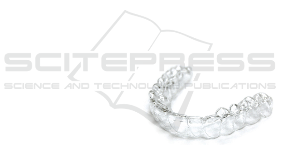
Treatments based on clear aligners are composed
of a set of thermoformed templates (Figure 1),
having different shapes, which are sequentially worn
by the patient (Kesling, 1943). Each aligner is
shaped a bit different than the real teeth position in
the mouth in order to force teeth to move in the
correct position. The shape of the last aligner
corresponds to the desired position of the teeth at the
end of the treatment. When the dentition have
reached the position imposed by the aligner, the
patient can wear the following aligner which
continues to move the teeth. A set of distinct
templates is usually required to achieve the final
desired outcome since each aligner can perform only
a limited rotation and/or translation. Usually, each
aligner needs about two weeks to completely exert
its specific function. When the dental technician
started to produce the first aligners, about 70 years
ago, they were made designing manually each of
them. The technician used a plaster cast of the
mouth and moved the teeth in the desired position
for the creation of the first aligner, then he had to
repeat the process until the last aligner of the
treatment. Nowadays through the increase of CAD
systems the design process has become faster and
has changed the market of these appliances. The
aligner's producers have changed from small local
laboratories to industries which can serve a large
amount of patient all over the world. (Beers, Choi,
and Pavlovskaia, 2003).
Figure 1: Example of a thermoplastic aligner.
The production process of these appliances is
composed of 3 distinct steps:
Creation of a digital model of the patient's
mouth
Design: The shape of each aligner is defined
by a technician through CAD software tools.
The technician designs the aligners starting
from the teeth position in the mouth obtained
by the digitalization process. Then following
doctor's prescription which indicates the
desired teeth position at the end of the
treatment with the aligners the technician
designs the aligners.
Aligner production.
Actually, the design is made mainly through
geometrical consideration about the teeth's crown
position almost neglecting the roots. This
simplification can bring to erroneous prediction
about the real treatment outcome. Roots can have
interferences between them during the treatment
causing an undesired final teeth position. Their
28
Savignano R..
Biomechanical Analysis of Orthodontic Appliances Through 3D Computer Aided Engineering.
Copyright
c
2014 SCITEPRESS (Science and Technology Publications, Lda.)
shape also influences very much the way how the
teeth move into the alveolar region.
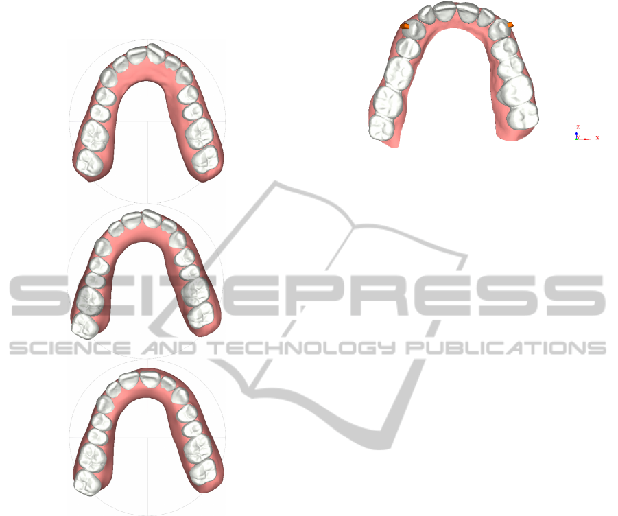
Figure 2: Virtual designed treatment. Initial teeth position
(upper), half-treatment (center), end of the treatment
(lower).
During the design phase, the technician can
suggest to the physician the application of
attachments, having particular shapes, onto some
teeth in order to facilitate the load transfer between
the aligner and the dentition. (Figure 3). A typical
attachment consists of dental composite material
which is polymerized onto the tooth surface.
Even if orthodontic treatments based on the use
of clear aligners are commonly used in clinical
practice there is no technical literature describing
how the loads are transferred from the thermoformed
aligner to the patient dentition. Since both design
and production processes involves many clinical and
technological skills (knowledge), the optimisation of
aligners features represents one of the most
challenging aspects of this kind of orthodontic
treatments. The design of customised and optimised
Figure 3: Attachments (orange) positioned on the two
upper canines teeth that have to be rotated.
templates would be of utmost importance to obtain
more effective treatment plans and accurate
prediction of the achievable results.
2 OUTLINE OF OBJECTIVES
The aim of the present research consists in the
development of a simulation model to be used in the
design of an orthodontic treatment by using
thermoformed aligners. Demanding problems are
given by the understanding on how each aligner
works on teeth, how load are transmitted from the
aligner to the teeth and what are the effects that can
be observed on the surrounding dental structures.
The objective of this research is to understand limits
and real effectiveness of clear aligners by using
FEM simulations.
Some of the characteristics which have to be
investigated and then optimised are:
Composite attachments shape and dimensions
with the aim at facilitating teeth movements;
Aligner thickness;
Aligner material properties;
Treatment strategies.
Production process
Model verification
3 RESEARCH PROBLEMS
Concerns encountered in the first part of the study
can be catalogued into three categories:
Creation of an accurate 3D patient mouth
model;
Estimation of the mechanical properties
characterising the involved dental structures;
Contact modelling between teeth and aligner;
BiomechanicalAnalysisofOrthodonticAppliancesThrough3DComputerAidedEngineering
29
3.1 Geometry Creation
The creation of a customised 3D digital mouth
model represents the starting point for each
simulation. This model should accurately reproduce
both bone and dental structures of the patient.
Recent developments in digital imaging techniques
have allowed a wide spread of three-dimensional
methodologies based on capturing anatomical tissues
by different approaches, such as CBCT, three-
dimensional photography and surface scanning.
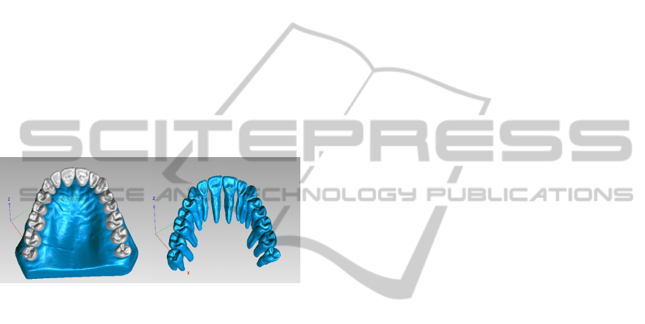
(Barone et al., 2013b). Figure 4 shows an example
of a patient model composed of maxillary bone and
teeth with their roots . Combining optical and
radiographic technologies (CBCT,
Orthopantomography) allows the evaluation of roots
morphology that usually is not available while
designing an orthodontic treatment with clear
aligners.
Figure 4: Reconstructed geometry of maxillary bone and
teeth(left) and teeth with roots reproduction.
A further problem is related to the aligner
modelling. The aligner is supposed to have a
constant thickness of 0.7 mm originating from the
mean thickness of the thermoplastic material disk
(having 0.75 mm thickness) after the thermoforming
process (Ryokawa, Miyazaki, Fujishima, & Maki,
2006).
However, possible thickness variations may
occur after the thermoforming process and should be
taken into account. Discontinuities in the aligner
thickness could modify its mechanical behaviour
during the orthodontic treatment.
3.2 Material Properties
Material properties must be correctly assigned to
each component of the model. Scientific literature
has been used to identify teeth and bone properties
(i.e.: Young's modulus and Poisson's ratio).
Periodontal ligaments properties are rather
characterised by different values and theories which
vary from linear elastic models to multiphase models
through literature (Fill, Toogood, Major, and Carey,
2012). Also for the aligner and the attachments the
material properties have to be appropriately
assigned. About the aligner the properties changes
due to the production process must be taken into
account.
3.3 Tooth-aligner Interface
A complex problem is related to the contact
conditions between the aligner and the teeth. In
particular, the interface between aligner and tooth
must be modelled. When simulations concerning
fixed orthodontic wires have to be performed, loads
can be supposed as concentrated and transferred
through a single point of the tooth crown. In many
cases, the wire can be neglected since not
meaningful for the simulation results except when
the aim of the study is to investigate the stress
generated along the wire (Penedo, Elias, Pacheco,
and de Gouvêa, 2010). When a clear aligner is used,
the transferring interface is represented by the
overall tooth crown geometry and the load
distribution over the contact surfaces is unknown.
The aligner could be disregarded within the model in
order to have faster simulations. This could be
possible only if the load distribution would be
known. However, the exact formulation of this
distribution represents a difficult task due to the high
irregular and patient-specific shape of the dentition.
4 STATE OF THE ART
Several studies about orthodontic biomechanics have
been performed by considering the problem from
different point of views. In the last few years, some
researchers have reported results of orthodontic
FEM simulations, starting from single tooth models
(Penedo, Elias, Pacheco and de Gouvêa, 2010) to
more complex multi-teeth models (Field, et al.,
2009). However, the majority of the presented
models refer to fixed orthodontic appliances and
only few studies focused on the study of orthodontic
treatments through clear aligners by using FEM
models (Martorelli, Gerbino, Giudice and Ausiello,
2013). Some recent experimental studies have been
focused on the measurement of load and torques
applied by an aligner onto the dentition model using
electronic devices based on strain gauges which are
connected to a replicated teeth arch (Hahn, et al.,
2010). Other studies used a pressure measurement
film in order to evaluate the force transferred by the
aligner to the teeth. (Barbagallo, Shen, Jones, Swain,
Petocz and Darendeliler, 2008).
Useful studies have
BIOSTEC2014-DoctoralConsortium
30
been published about the material properties of some
different thermoformed aligners and can probably
help us in the research development (Kohda, Iijima,
Muguruma, Brantley, Ahluwalia, and Mizoguchi,
2013). Some studies are related to the material
properties before thermoforming while others
investigate the mechanical properties after
thermoforming and trying to replicate the real
working environment of the aligner (Ryokawa,
Miyazaki, Fujishima, and Maki, 2006).The
mechanical properties of the dental structures have
been well studied and the properties of tooth and
bone structures are almost the same in most of the
papers, but there is a different situation regarding the
periodontal ligament.
A lot of literature regards the periodontal
ligament mechanical properties. However, it is really
hard to investigate its in-vivo properties due to its
small dimensions (about 0.2 mm thickness). For this
reason, the majority of the available papers
investigated the mechanical properties of the
periodontal ligament through experimental analyses.
Typical values for the periodontal ligament
Young Modulus (E) vary from 0,059 MPa to 1750
Mpa (Fill et al., 2012). This great difference is due
to the different assumptions and the different
environments considered in each research. Some of
the experiments have been performed during
masticatory load simulation (Natali, Pavan and
Scarpa, 2004)while some others during orthodontic
simulation (Penedo, Elias, Pacheco, & de Gouvêa,
2010). Another reason of this results are the
biological differences between the subjects
considered in each research. All the assumption
made by researchers caused a great variability of the
properties estimated for the periodontal ligament.
5 METHODOLOGY
5.1 Geometry Creation
In the present study, dental data, captured by
independent imaging sensors, are fused to create
multi-body orthodontic models composed of teeth,
oral soft tissues and alveolar bone structures. The
methodology is based on integrating CBCT and
surface structured light scanning (Barone et al.,
2013a). An optical scanner is used to reconstruct
tooth crowns and soft tissues (visible surfaces)
through the digitalization of plaster casts. These data
are also used to guide the segmentation of internal
dental tissues (tooth roots) by processing CBCT data
sets. The 3D individual dental tissues obtained by
the optical scanner and the CBCT sensor are fused
within multi-body orthodontic models with
minimum user interaction. The final orthodontic
model is provided by the fusion of the multi-modal
data sets including the most accurate representation
for each tissue: i.e., tooth crowns and gingiva by
optical scanning and tooth roots and alveolar bone
by CBCT imaging. The created anatomical geometry
is converted into “Iges” models in order to be
imported within a Finite Element modeller software
(Ansys
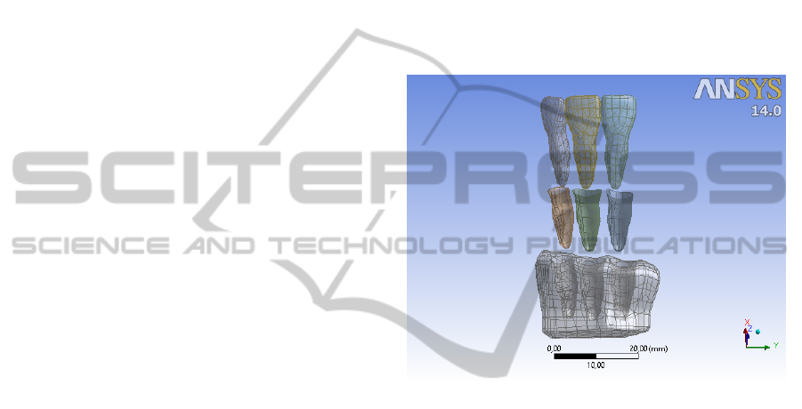
14). The periodontal ligament has been
modelled as an uniform 0.2 mm thickness shell
between tooth and bone (Figure 5).
Figure 5: View of the model with three teeth with their
periodontal ligaments and underlying bone.
The aligners are always created by
thermoforming a disc of thermoplastic material on a
cast obtained by a rapid prototyping machine. The
disc thickness can vary depending on the producer,
but an often used thickness is 0.75 mm, so has been
decided to start the study using this value. To
simulate the aligner creation the teeth have been
combined and the resulting object has been cut
manually over the gingival margin to obtain a thin
object (0.7 mm) that wears well on teeth surfaces.
Assuming a constant thickness for the aligner is a
simplification that can bring to some errors in the
simulation results, so an alternative way can be to
create the model for the aligners using an optical
scanner to acquire the aligner geometry and then to
create the geometry readable by the finite element
modeller in order to have a more realistic model.
5.2 FEM Simulation
The bodies have been meshed dividing them into
solid and shell bodies. The teeth, bone and the
BiomechanicalAnalysisofOrthodonticAppliancesThrough3DComputerAidedEngineering
31
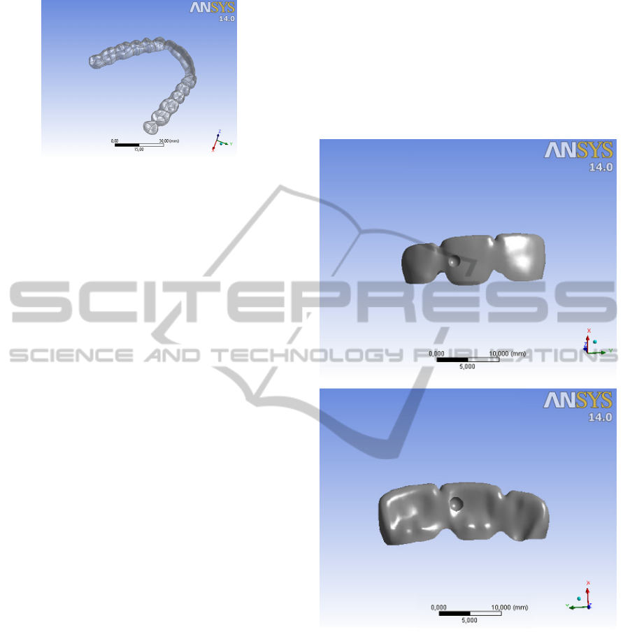
Figure 6: Model of the orthodontic aligner.
attachment have been modelled as solid bodies using
tetrahedrons. The periodontal ligaments and the
aligner have been modelled as shell bodies due to
their small thickness.
The simulation phase started with the creation of
a single tooth model, then the complexity has been
increased in order to obtain a more complete and
realistic simulation.
For the single tooth model has been used an
upper central incisor. The single tooth model has
been used only in the first time while trying to
replicate a well working model for orthodontic
simulation with brackets (Penedo, Elias, Pacheco, &
de Gouvêa, 2010). Couldn't be used the single tooth
model while simulating the treatment with the
removable aligner because is not possible to model
the mesial and distal extremity of the aligners.
Cutting the aligner at the mesial and distal side
brought to an erroneous result because the aligners
completely followed the tooth while not having any
grip point. Also closing the aligner on the mesial and
distal sides brought to the same problems, so has
been used this model to simulate a torque movement
and to "validate" the chosen model.
With three teeth the aligner has the right grip
point to generate forces on the teeth. The three teeth
model comprised the upper central incisor and the
two neighbours teeth. The first simulation was
related to a 2° clockwise rotation of the upper central
incisor. The simulation was performed using three
different appliances features. In the first case was
used a common clear aligner, in the second case has
been added a composite attachment on the tooth that
is commonly used to help this kind of tooth
movement. In the third case we used an aligner with
an introflection on the lingual surface and an
introflection on the vestibular surface that are
positioned in order to concentrate the force on the
tooth and are supposed to help achieving a better
result.
The idea for the next phases of the research is to
perform the simulation using a full dental arch to
have a more realistic situation and simulating
different shape and dimensions of the composite
attachments and different aligner thickness to find
the best configuration for the different teeth
movements. Then could be simulated a complete
treatment of a set of aligners that involves bone
remodelling evaluations (Qian, Fan, Liu and Zhang,
2008).
Figure 7: Introflection on vestibular and lingual surfaces.
5.2.1 Material Properties
Data have been then transferred to the finite element
modeller (Ansys
14). The structures of the mouth
have been distinguished in three different parts:
Bone;
Teeth;
Periodontal ligaments.
There is no distinction between Cancellous and
Cortical bone, because of the very higher stiffness of
the second one. For the same reason also the teeth
are not divided into: Dentin, Enamel, Pulp, but each
tooth is considered a homogeneous body .This
BIOSTEC2014-DoctoralConsortium
32
simplification has been made in previous studies
(Penedo, Elias, Pacheco and de Gouvêa, 2010) to
save computational time without losing many
information if the aim of the research it's not to
study the single part, but as in this case to evaluate
the effects of the treatment in a more macroscopic
way.
The material properties that have been used are:
Table 1: Material properties.
Young's Modulus
[MPa]
Poisson's
Ratio
Tooth 20000 0.3
Bone 13800 0.3
Periodontal
ligament
0.059 0.49
The most difficult choice regards the model to be
used to simulate the ligament properties since many
are the biomechanical models available in literature.
Some researchers assumed a viscoelastic model
for the periodontal ligament(Su, et al., 2013), which
seems to simulate well the time-dipendent properties
of the ligaments.
However in this phase of the research, the linear
elastic model has been used since the project is more
focused on the comparison of the results obtained by
using different properties of the appliances rather
than on the study of the behaviour of the ligament
itself. In a further stage of the research, different
assumptions regarding the periodontal ligament
model could be introduced in order to refine the
investigations.
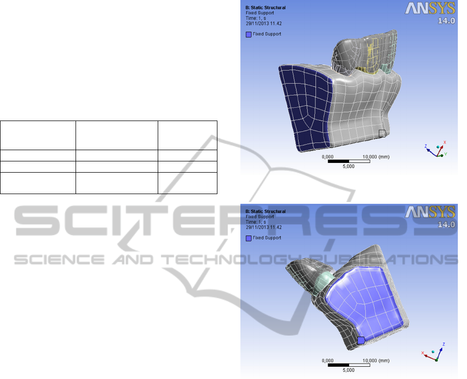
5.2.2 Boundary Conditions
The tooth and the ligament are joined by a bonded
contact which allows only small sliding movements
between joined nodes. The same connection has
been used to join bone and ligament. The mesial and
distal faces of the bone have been fixed to the
ground (Figures 8-9).
5.2.3 Creating Teeth-aligner Displacement
The created aligner is completely congruent with
teeth. For this reason, a difference between aligner
and dentition geometry has been generated in order
to simulate a real treatment condition. As a first
example, the treatment simulation during the
rotation of an upper central incisor has been
investigated. This has been done through the finite
element modeller by defining the tooth principal axis
and clockwise rotating the upper central left incisor
by 2° around its axis.
Figure 8: Distal view of the model.
Figure 9: Mesial view of the model.
5.2.4 Analysis Settings
Once the models are created, two are the possible
strategies to solve the problem. The first one consists
of positioning the aligner onto the dentition and let
the software to solve the contact problem in order to
obtain a stable condition. In a second strategy, the
aligner is positioned over the teeth (Figure 10) and
then it is slowly moved until it reaches the contact
condition with teeth. This second approach, which
needs more computing time, gives further
information about the use of the aligners in
orthodontic treatments. It is indeed possible to
analyse the wearing phase, which is characterised by
high and not negligible stresses. Moreover, the
evaluation of the stress distribution could allow the
prediction of possible aligner fractures.
BiomechanicalAnalysisofOrthodonticAppliancesThrough3DComputerAidedEngineering
33
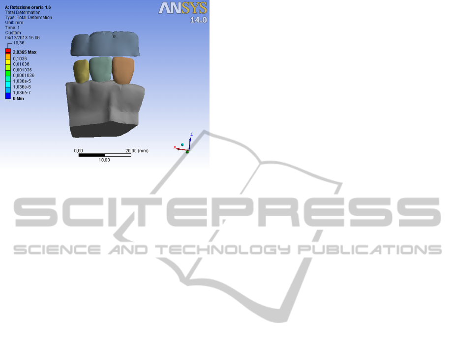
Figure 10: Aligner over the teeth at the starting point of
the simulation.
5.3 Model Validation
After obtaining the desired results from the
simulations will be performed an experimental
validation comparing them with that obtained by
other techniques. Some ideas are:
5.3.1 Photoelasticity
Photoelasticity is a full-field technique which
directly provides the information of principal stress
difference and the orientation of principal stress
direction by fringe analysis of components made of
birifrangent materials. The thermoplastic material
which composes the aligner is transparent and is
characterized by having photoelastic properties. The
introduction of customized photoelastic analyses for
real components would greatly enhance the
detection of possible criticalities arising from a
challenging application such as the optimisation of
removable aligners.
5.3.2 Electronic Measurement Device
Some researchers have developed electronic
systems, based on strain gauges, able to measure
forces and moments during a simulation of an
orthodontic treatment. The comparison between the
FEM model with the measurements obtained by the
electronic device can give an idea about the
accuracy of the model. (Hahn et al., 2010)
5.3.3 Clinical Tests on Real Patients
The best way to validate the model would rely on
the comparison of the numerical results with those
obtained by clinical tests involving real orthodontic
treatments.
6 EXPECTED OUTCOME
The present research project is focused on the study
of how the orthodontic aligners work and on the
optimization of their design process. The appropriate
definition of parameters as shape, dimensions of
attachments, thickness and material of the aligner
would allow the definition of a more predictable
treatment. Moreover, shorter treatment times would
be characterized by less discomfort for the patient
and lower costs since performed by a lower number
of aligners.
The results obtained by this research could be
also used to extend the use of invisible aligners to
malocclusion problems which are presently treated
by different orthodontic appliances, and to improve
their production process.
REFERENCES
Barbagallo, L., Shen, G., Jones, A., Swain, M., Petocz, P.,
& Darendeliler, M. (2008). A novel pressure film
approach for determining the force imparted by clear
removable thermoplastic appliances. Annals of
Biomedical Engineering , 335-341.
Barone, S., Paoli, A., & Razionale, A. (2013b). Computer-
aided modelling of three-dimensional maxillofacial
tissues through multi-modal imaging. Proceedings of
the Institution of Mechanical Engineers, PArt H:
Journal of Engineering in Medicine , 227,89-104.
Barone, S., Paoli, A., & Razionale, A. (2013a). Creation of
3D Multi-Body Orthodontic Models by Using
Independent Imaging Sensors. Sensors , 13,2033-
2050.
Beers, A., Choi, W., & Pavlovskaia, E. (2003). Computer-
assisted treatment planning and analysis. Orthodontics
& craniofacial research , 117-125.
Field, C., Ichim, I., Swain, M., Chan, E., Darendeliler, M.,
Li, W., et al. (2009). Mechanical responses to
orthodontic loading: A 3-dimensional finite element
multi-tooth model. American Journal of Orthodontics
and Dentofacial Orthopedics , 174-181.
Fill, T. S., Toogood, R. W., Major, P. W., & Carey, J. P.
(2012). Analytically determined mechanical properties
of, and models for the. Journal of Biomechanics , 9-
16.
Hahn, W., Engelke, B., Jung, K., Dathe, H., Fialka-Fricke,
J., Kubein-Meesenburg, D., et al. (2010). Initial forces
and moments delivered by removable thermoplastic
appliances during rotation of an upper central incisor.
Angle Orthodontist , 80,2,239-246.
BIOSTEC2014-DoctoralConsortium
34

Kesling, H. (1943). The philosophy of the tooth
positioning appliance. American Journal of
Orthodontics and Oral Surgery , 297-304.
Kohda, N., Iijima, M., Muguruma, T., Brantley, W.,
Ahluwalia, K., & Mizoguchi, I. (2013). Effects of
mechanical properties of thermoplastic materials on
the initial force of thermoplastic appliances. Angle
Orthodontist , 476-483.
Martorelli, M., Gerbino, S., Giudice, M., & Ausiello, P.
(2013). A comparison between customized clear and
removable orthodontic appliances manufactured using
RP and CNC techniques. Dental Materials , e1-e10.
Natali, A., Pavan, P., & Scarpa, C. (2004). Numerical
analysis of tooth mobility: Formulation of a non-linear
constitutive law for the periodontal ligament. Dental
Materials , 623-629.
Penedo, N., Elias, C., Pacheco, M., & de Gouvêa, J.
(2010). 3D simulation of orthodontic tooth movement.
Dental Press Journal of Orthodontics , 98-108.
Qian, Y., Fan, Y., Liu, Z., & Zhang, M. (2008). Numerical
simulation of tooth movement in a therapy period.
Clinical Biomechanics , s48-s52.
Ryokawa, H., Miyazaki, Y., Fujishima, A., & Maki, K.
(2006). The mechanical properties of dental
thermoplastic materials in a simulated intraoral
environment. Orthodontic Waves , 64-72.
Su, M., Chang, H., Chiang, Y., Cheng, J., Fuh, L., Wang,
C., et al. (2013). Modeling viscoelastic behavior of
periodontal ligament with nonlinear finite element
analysis. Journal of Dental Sciences , 8,2,121-128.
BiomechanicalAnalysisofOrthodonticAppliancesThrough3DComputerAidedEngineering
35
