
Communication Reduced Interaction Protocol between Customer,
Charging Station, and Charging Station Management System
Karl-Heinz Krempels
1
, Christoph Terwelp
1
, Stefan W
¨
uller
1
, Tilman Frosch
2
and Sevket G
¨
okay
1
1
Information Systems & Databases, RWTH Aachen University, Aachen, Germany
2
HGI, Ruhr-University Bochum, Bochum, Germany
Keywords:
Charging Station, Interaction Protocol, Authentication Protocol, Reduced Communication Effort, QR Code.
Abstract:
The emerging build-ups of charging station infrastructures require sufficiently secure and economic authen-
tication protocols. Existing protocols for the purpose of authenticating a customer against a charging station
have the inherent disadvantage that they expect a network connection to the management system, produce a
communication overhead, or might reveal sensitive customer data depending on the protocol. The protocol,
provided by us, enables a multiple-operator customer-to-charging station authentication system. The particu-
larity of the protocol is that it does not require a permanent network connection between charging stations and
a corresponding management system, reduces the communication overhead between the involved entities, and
protects sensitive customer data at a high rate.
1 INTRODUCTION
The availability of a charging infrastructure is one of
the decisive factors for the success of electric vehi-
cles. Thus, one can currently observe significant ef-
forts in Germany and many other countries to expand
the existing charging infrastructure. In the course
of this expansion, costs must be kept in check. Be-
sides the acquisition costs, installation and mainte-
nance costs should be kept as low as possible. One
factor within the operational costs is the need for a
continuous communication channel between charging
stations and a corresponding charging station man-
agement system.
The interaction protocol we propose in this pa-
per enables a dynamic control of charging stations
without the necessity of a constant communication
channel to a management system. This is achieved
by leveraging the Internet connection of the cus-
tomer’s smartphone as a communication channel be-
tween charging station and charging station manage-
ment system for authentication purposes.
The remainder of the paper is organized as fol-
lows: In Section 2 we describe authentication pro-
tocols for charging stations that are currently in use.
Section 3 and 4 provide a detailed description of the
our solution and optional protocol extensions. In Sec-
tion 5, we discuss core design decisions and give a
summary of the advantages of our protocol and the
provide the possibility to extend its application field
in Section 6.
2 RELATED WORK
In the following we present the state of art of pro-
tocols used to authenticate customers against charg-
ing stations. The major disadvantage of those proto-
cols is the costly communication effort needed before
and after each charging process between the charg-
ing station and the charging station management sys-
tem. The interchanged data basically consists of cus-
tomer’s authentication data, information for the ad-
justment of meter readings, as well as control com-
mands, e.g., the activation of the charging station.
Partially, the protocols enable a local authentication
by utilizing whitelists (OCPP Steering Group, 2012).
However, this jeopardizes the confidential customer
data which are deposited within the charging station.
Furthermore, the following protocols rely on a
network connection, i.e., a network connection is es-
sential for the commissioning of a charging station.
Below, we will show that a network connection is
not absolutely necessary to fulfill the requirements of
those systems.
118
Krempels K., Terwelp C., Wüller S., Frosch T. and Gökay S..
Communication Reduced Interaction Protocol between Customer, Charging Station, and Charging Station Management System.
DOI: 10.5220/0004971801180125
In Proceedings of the 3rd International Conference on Smart Grids and Green IT Systems (SMARTGREENS-2014), pages 118-125
ISBN: 978-989-758-025-3
Copyright
c
2014 SCITEPRESS (Science and Technology Publications, Lda.)

2.1 Authentication Via RFID-card
(OCPP Steering Group, 2012)
The customer owns an RFID-card which enables him
to authenticate against a charging station with an in-
tegrated RFID-reader. If the read ID appears on the
charging station’s local whitelist, the user is success-
fully authenticated against the charging station with-
out involving the charging station management sys-
tem into the authentication process. Otherwise, if the
ID does not appear on the whitelist, there has to be
a data exchange between the charging station and the
charging station management system. The customer
logoff works analogously. Meter readings and control
data is communicated using the network connection
to the charging management system.
2.2 Authentication Via Plug and Charge
(ISO, 2013)
The costumers connects his vehicle with a charging
station by a charging cable carried along. The au-
thentication is done in two steps. The charging cable
plug is endued with an RFID-chip. If the plug of the
charging cable is in an appropriate range the ID is read
by the RFID-reader of the charging station. Reading
a valid ID induces the charging station to open it’s
socket. For the second authentication step the com-
munication channel established by the charging cable
is used. A certificate which is deposited within the ve-
hicle is used in the underlying protocol to authenticate
the customer against the charging station. The charg-
ing process is terminated by unplugging the charging
cable.
The verification of the authentication data and the
exchange of meter readings is ensued via the network
connection to the charging station management sys-
tem.
2.3 Authentication Via Hotline
The customer dials the operator’s hotline which is
fixed on the charging station and communicates his
user ID, password and the charging station ID. A
successful verification induces the activation of the
charging station for the authenticated customer. The
customer logoff works analogously.
Meter readings and control data is communicated
using the network connection to the charging manage-
ment system.
2.4 Authentication Via Internet
The authentication via Internet proceeds analogously
to the authentication via hotline. The customer com-
municates user ID, password, and charging station ID
by filling the appropriated form on the website of the
charging station operator or using a provided smart-
phone application for this purpose.
3 THE BASIS PROTOCOL
Before we describe the details of our protocol, we
give a concise overview with Section 3.1. The pro-
tocol flow is given by the sequence diagrams depicted
in Figure 1 and 2. During an initialization phase
each charging station (CS) is endued with a pub-
lic/private key pair (pk
CS
, sk
CS
) and the public key(s)
of the respective charging station management sys-
tem(s) (pk
CSMS
i
), respectively. The charging station
management system (CSMS) retains a matching pri-
vate key and the public key of each charging station.
Keys are stored in a non-removable secure storage,
from which they cannot be extracted by unauthorized
entities. When a new user signs up with a provider,
he receives a set of unique credentials to authenticate
at the CSMS.
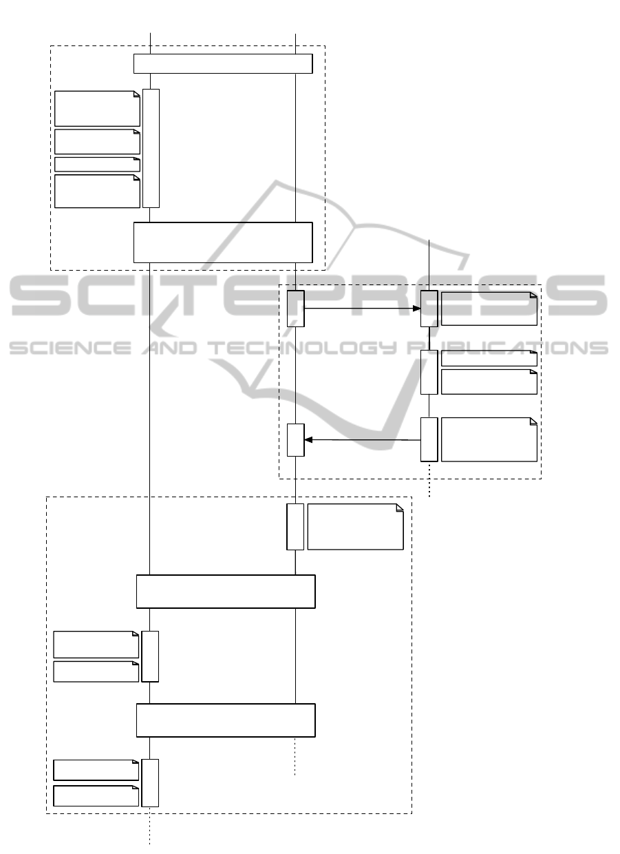
3.1 Protocol Flow
On the push of a button integrated into the CS, it gen-
erates a QR code and shows it on its display. The cus-
tomer scans the QR code using his smartphone and
communicates its content in combination with his au-
thentication data to the CSMS. Optionally, the user
can provide additional position information using the
provided smartphone application, e.g., his GPS coor-
dinates. The CSMS provides the user with authen-
tication information for this CS, which the applica-
tion on the user’s smartphone displays as a QR code.
The CS scans this QR code from the phone’s dis-
play. If the authentication information is valid, it un-
locks / enables the power socket. Charging ends when
the electric vehicle’s battery management signals suf-
ficient charge, the customer presses a button at the
CS and presents the QR code again, or the customer
manually releases the power cable using a mechan-
ical release device integrated in his vehicle. When
charging ends, the CS creates a data tuple to be used
for billing and stores it in temper-evident memory.
The CSMS periodically tries to connect to every CS.
When successful, it recovers all billing data tuples re-
tained within the CS.
CommunicationReducedInteractionProtocolbetweenCustomer,ChargingStation,andChargingStationManagement
System
119
charging station
management system
charging station
randomly generate
auth. token T of bit
length 256
customer scans QR code using his
smartphone application
c, customer ID, password
verify authentication
data
m = dec
sk
CSMS
(c)
verify signature and
check t
i
smartphone
(customer)
m'
charging station scans QR code
from customer's smartphone display
verify signature, t
i
,
and T
start charging
customer connects charging station
and vehicle through charging cable
lock plug
customer authentication against the
charging station management system,
handing out the PIN
(secured via SSL)
generation of the QR code
authentication of customer against charging station,
charging initiated
((pk
CS
, sk
CS
), pk
CSMS
)
(customer ID, password)
((pk
CSMS
,sk
CSMS
),
pk
CS
1
, pk
CS
2
, …)
customer pushes the button
m =
(t
i
, T, sig
sk
CS
(ti,T))
c = enc
pk
CSMS
(m)
generate a QR
code from c and
display it
m' =
(t
i
, T, ID
C
,
sig
sk
CSMS
(t
i
, T, ID
C
))
generate QR code
from m' and display it
open socket
Figure 1: Basis Authentication Protocol (Part 1).
SMARTGREENS2014-3rdInternationalConferenceonSmartGridsandGreenITSystems
120
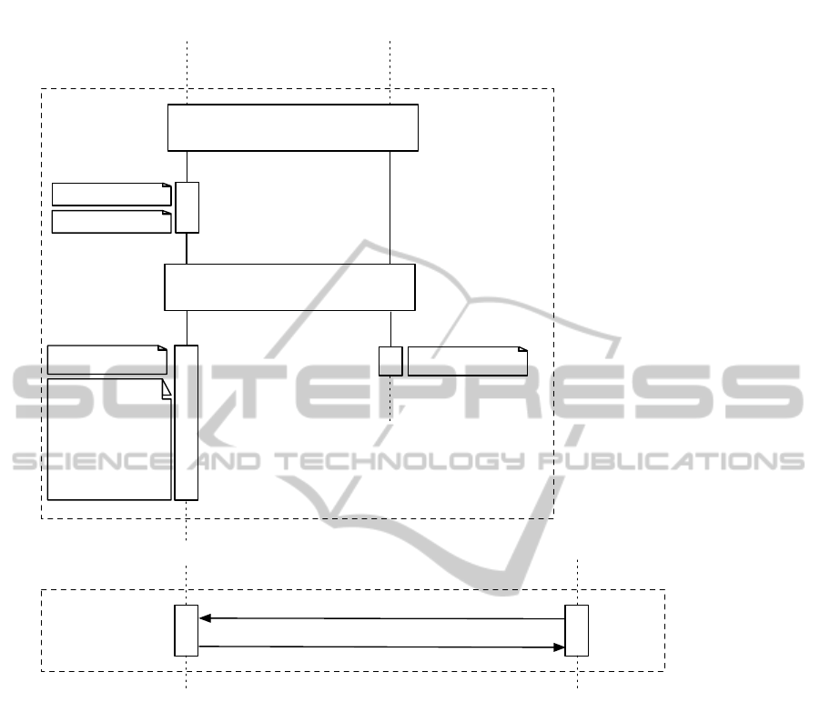
customer presents QR code again
to the charging station
stop charging
leave parking lot
customer removes charging cable
close socket
sign out and termination of the charging
process
verify signature
billing data
exchange
request billing data
tuple
tuple =
(t
start
, t
end
, meterID,
Z
t
start
, Z
t
end
, ID
C
,
sig
sk
CS
(t
start
, t
end
,
meterID, Z
t
start
,
Z
t
end
, ID
C
))
charging station
(pk
CS
, sk
CS
, pk
CSMS
)
smartphone
(customer)
(customer ID, password)
charging station
management system
((pk
CSMS
,sk
CSMS
),
pk
CS
1
, pk
CS
2
, …)
Figure 2: Basis Authentication Protocol (Part 2).
3.2 QR Code Generation
On the push of a button the CS randomly chooses an
authentication token T of 256 bit length. It only cre-
ates n tokens per time t. n, t are chosen as a compro-
mise between usability and security. Here, usability
primarily concerns the fact that each customer willing
to use the system should be able to receive an unused
token. Under a security perspective one must consider
that the source of randomness must not be exhausted
or the system overloaded by very frequent pressing
of the button, where each button press triggers a set
of cryptographic operations that consume system re-
sources.
The CS creates a message m = (timestamp =
t
i
, token = T, signature = sig
sk
CS
(t
i
, T )), creates c =
enc
pk
CSMS
i
(m), and creates a QR code containing c
that it displays to the customer. t
i
is a timestamp pro-
duced at message creation, in a non-ambiguous time
representation. The customer scans this QR code us-
ing his smartphone application.
3.3 Customer Authentication
The smartphone application connects to the CSMS
using a secure variant of Transport Layer Security
(TLS), a cryptographic protocol frequently used to se-
cure a cornucopia of communications on the Internet,
e. g., for online banking. We recommend to use TLS-
DHE, which has recently been proven to be secure by
Jager et al. (Jager et al., 2012).
The user authenticates himself at the CSMS and
establishes a secure session. Within this session the
application transmits the message c contained in the
CS’ QR code which the CSMS decrypts and veri-
fies. After successful verification the CSMS checks
CommunicationReducedInteractionProtocolbetweenCustomer,ChargingStation,andChargingStationManagement
System
121

whether t
i
is within a defined time period to be con-
sidered fresh. Optionally, the user can provide addi-
tional position information using the provided smart-
phone application, e.g., his GPS coordinates. We
discuss this extension in Section 4. The CSMS
transmits a message m
0
= (timestamp = t
i
, token =
T, customerID = ID
c
, sig
sk
CSMS
(t
i
, T, ID
c
)) back to the
application. ID
c
is a unique identifier for the authen-
ticated customer. The application creates a QR code
from m
0
, which the user presents to the CS. The CS
scans the QR code and verifies m
0
and T . If T and
the signature over T, customerID is valid, and t
i
is
within a defined time period, the power socket is un-
locked / enabled.
3.4 Storage and Transmission of Billing
Data
Upon the end of the charging process, the CS creates a
data tuple for billing and ensures its authenticity dur-
ing transport and storage by means of a digital signa-
ture. The tuple is formed as
tuple =(t
start
, t
end
, meterID, Z
t
start
, Z
t
end
, ID
c
,
sig
sk
CS
(t
start
, t
end
, meterID, Z
t
start
, Z
t
end
,
customerID)),
where t
start
is a timestamp recorded upon starting
to charge, t
end
is a timestamp indicating the end of
charging, meterID is the unique identification num-
ber of the energy meter (if required by local regu-
lation), Z
t
start
and Z
t
end
are the energy meter values
at beginning an end of charging, respectively. We
chose digital signatures over symmetric methods such
as Message Authentication Codes, as both can ensure
message integrity and authenticity, but the former can
also provide non-repudiability. Non-repudiability is
essential to be able to prove that only the respective
CS could have created the signed tuple. However, this
objective cannot be reached using means of symmet-
ric cryptography.
The CS stores the data tuple in temper-evident
memory, such that any attempt to erase a billing tu-
ple can be discovered. The CSMS periodically tries
to connect to each CS. Upon successfully establishing
a secure connection, it recovers all billing data tuples
and stores them centrally, such that they are available
for the billing process. When the CSMS has success-
fully stored and verified a tuple, this tuple is remove
from the CS’ memory.
4 PROTOCOL EXTENSIONS
In the following we describe further optional exten-
sions to the basis protocol which affect the security
of the protocol and the cooperation between different
charging station operators.
4.1 QR Code Relay Attack Prevention
We consider the following theoretical attack scenario:
An attacker positions a manipulated charging station
with the ability to receive QR code data generated by
the attacker and to display it to the customer.If an au-
thentication token is read by the manipulated charging
station, it has to be transmitted immediately to the at-
tacker whereas an error message is displayed to the
customer. An existing connection to the charging net-
work is not necessary to accomplish this task. Utiliz-
ing the manipulated charging station to his own au-
thorization process the attacker is enabled to charge
his vehicle for free or at the cost of the victim.
The attacker positions his vehicle in front of an
authorized charging station, reads the displayed QR
code, sends the QR code data to the manipulated
charging station (e.g. using an implemented smart-
phone application for this purpose), and waits until
the valid QR code, provided by the customer at the
manipulated charging station, is received. If the QR
code loses validity during the transmission, the at-
tacker repeats the proceeding with a fresh QR code.
In this scenario, the charging station management sys-
tem provides an authentication token for an autho-
rized customer and connects the billing information to
his account. Once the customers presents the QR code
to the manipulated charging station, an error message
is displayed, informing about a defective and refer-
encing to another charging station. Since the cus-
tomer cannot distinguish between the authorized and
the manipulated charging station, he is not aware of
the fact that an attacker positioned at another charg-
ing station uses his QR code to charge a vehicle at
his cost. Under certain assumptions, this attack can
be thwarted by integrating spatial data into the au-
thentication protocol: The mobile application deter-
mines the customer’s GPS coordinates during authen-
tications. This position is then concatenated to the
message c the customer transmits to the charging sta-
tion management system.
With this protocol extension, the charging sta-
tion management systems checks if the customer’s
GPS coordinates match with corresponding charging
station’s coordinates considering a certain tolerance.
Only if this additional condition is satisfied the man-
agement systems issues m
0
. The assumption for this
SMARTGREENS2014-3rdInternationalConferenceonSmartGridsandGreenITSystems
122

security feature is that the manipulated and the autho-
rized charging station the attacker uses are sufficiently
wide apart from each other exceeding the maximal ac-
cepted tolerance.
4.2 Multi-operator Authentication
A simple extension to the basis protocol of Section
3 enables a multi-operator authentication without the
necessity of sharing customer data between operators.
Each operator obtains an operator ID. Instead of just
pressing a button, the customer chooses the operator
at the CS. The CS encrypts the message m using the
respective operator’s public key pk
CSMS
i
and then in-
corporates the appropriate operator ID within the QR
code in plaintext. Basing on the operator ID, the pro-
vided smartphone application decides which operator
the authentication message is forwarded to.
Manipulating the operator ID can not harm the system
because the assigned operator is not able to decrypt
the data which is necessary to return an authentica-
tion token to the customer.
4.3 Privacy-preserving Solution
Locational privacy can be defined as ’the ability of
an individual to move in public space with the expec-
tation that under normal circumstances their location
will not be systematically and secretly recorded for
later use’ (Andrew J. Blumberg and Peter Eckersley,
2009) and has become increasingly relevant with rise
of long-term data retention – itself made facilitated by
increasingly cheap data storage.
While the solution we presented so far does not
preserve a customers location privacy – it allows
for the creation of a movement profile based on the
spatio-temporal location of each charging process –
a limited set of changes can mitigate this threat: In-
stead of sporadically connecting to the Internet to
allow for the CSMS to retrieve billing data, each
CS uses this temporary Internet link to connect to
the Tor network (Mathewson et al., 2004), such that
it is addressable as a location-hidden service. This
means, it is known to the CSMS via its .onion ad-
dress, but not via its IP address or physical loca-
tion. While this may sound far-fetched and imprac-
tical in reality, the Tor network is a highly redundant,
distributed system that can provide connectivity with
sufficient throughput and latency for the application
at hand (Frosch et al., 2013). The authenticity and
non-repudiation of messages from CS to CSMS does
not longer depend on classical signature algorithms.
Instead, messages are signed using a group signa-
ture scheme, like XSGS (Delerabl
´
ee and Pointcheval,
2006). Message m will be formed as (timestamp =
t
i
, token = T, address = onionaddress
CS
, signature =
gsig(t
i
, T, onionaddress
CS
)), while c will still be cre-
ated as enc
pk
CSMS
i
(m). Instead of signing the billing
data tuple with a conventional signature, the CS uses
the a modified eXtremely Small Group Signature as
proposed by Frosch et al. (Frosch et al., 2013).
5 DISCUSSION
In the following we discuss the potential of a com-
pletely offline solution, the advantages of using a ran-
dom binary token over a numeric Personal Identifica-
tion Number (PIN), as well as, the issue of a trustwor-
thy time source.
5.1 Offline Solution
In the unlikely case that a charging station is lo-
cated such that it can never access the Internet,
small changes can be made to the protocol leverage
the user’s communication with the CSMS to trans-
port most billing relevant data within. Including
the current energy meter value Z
t
i
in message m,
such that m = (meter = Z
t
i
, timestamp = t
i
, token =
T, signature = sig
sk
CS
(Z
t
i
, t
i
, T )). The charging pro-
cess can only be terminated by performing the authen-
tication procedure again, such that a message m
2
=
(meter = Z
t
j
, timestamp = t
j
, token = T
0
, signature =
sig
sk
CS
(Z
t
j
, t
j
, T
0
)) is transmitted to the backend.
However, as many electric vehicles come with a man-
ual unlock mechanism for the power connector, even
a honest, but curious, customer can evade the trans-
mission of m
2
and thus charge without paying. Ad-
ditionally, t
i
, t
j
are created when the customer presses
a button and not at the exact time the charging starts.
Depending on local legislation, this may not be pre-
cise enough.
5.2 Random Token vs. Random PIN
Although numeric PINs are frequently used to authen-
ticated customers, e. g., at automatic teller machines
(ATMs), the keyspace of usable-length PINs is very
limited. PIN lengths up to 6 digits can be considered
acceptable to the customer, as they are used in com-
mercial applications. However, as the character reper-
toire is limited to [0..9], the keyspace is limited to 10
l
.
The probability that an attacker guesses a valid pass-
word is thus
1
10
l
, i. e., on average an attacker needs
b
10
l
2
c guesses. As this limitation is well known, many
PIN-based authentication systems require not only the
CommunicationReducedInteractionProtocolbetweenCustomer,ChargingStation,andChargingStationManagement
System
123

knowledge of the PIN but also the possession of phys-
ical token, e. g., a bank card. Additionally, usability is
further reduced by the fact that a customer may only
mistype a PIN n times, before the physical token is
automatically invalidated or confiscated. n is often
chosen as 3.
By choosing a QR code reader as input method to
the charging station, instead of a PIN pad, we avoid
the usability issue altogether. The user is not forced to
enter an arbitrary set of numbers correctly, but simply
presents his smartphone to the reader. Thus, we can
choose to a much longer knowledge-based authenti-
cation token. We choose a binary token of 256 bit
length, which results in a keyspace of 2
256
. This
allows for a significantly more secure authentication
process and also improves usability as there is no need
enforce arbitrary limitation on how often a user may
try to enter a credential. Vandalism-proof QR-code
readers are widely in use today, e.g., at airport board-
ing terminals.
5.3 Time Source
We use a timestamp as a freshness parameter in our
protocol. However, this implies that we have a trust-
worthy time source at our disposal. This is also a ba-
sic assumption for post-paid systems, as many regula-
tions require to inform the customer when a service or
a good has been delivered. When an attacker can trick
a CS into assuming a time in the past as being current,
he can thus replay an old message m
0
old
, which will
be accepted if the CS’s time and the message times-
tamp are within a tolerated interval. Even existing
customers can use erroneous system times to their ad-
vantage, as the energy provider will have a hard time
arguing how it can bill, e.g., for a charging process
with at timestamp dating from before the customer
ever signed up with this provider.
However, a trusted time source is not easy to come
by. DCF-77, the Network Time Protocol (NTP), and
GPS are popular time sources. However, none of
these protocols provide information on the authentic-
ity of the content and can thus be manipulated. DCF-
77 transmitters can be built for very limited costs
1
or
even using standard soundcards
2
. NTP packets can be
manipulated in the path of communication. Alterna-
tively, DNS entries can be hijacked by an out-of-path
attacker (Leyden, 2013), pointing to an NTP server
the attacker controls. While Tippenhauer et al. (Tip-
penhauer et al., 2011) have shown that the spoofing
of a GPS signal is feasible, this attack induces signifi-
1
http://endorphino.de/projects/electronics/timemanipula
tor/index en.html
2
http://0x7.ch/text/dcf77.pdf
cantly higher costs for the attacker than the aforemen-
tioned ones. For the time being, GPS should be the
preferred time source for outdoor CS installations. In
indoor areas, such as parking garages, the GPS time
signal can be forwarded via internal network. Alter-
natively, tlsdate (Applebaum, 2013) may provide
a coarser, but possibly more secure alternative time
source when used as consensus source.
6 CONCLUSION
We presented a protocol that enables providers to op-
erate charging stations without a continuous commu-
nication channel connecting them to the charging sta-
tion management system. This allows a more eco-
nomical operation and a higher security of the charg-
ing station infrastructure, as the charging station has
no privileged access to the backend infrastructure. In-
volving QR codes enables a multi-operator authen-
tication of the customer against the charging station
without any communication between the charging sta-
tion and the management system and without deposit-
ing sensitive data on the charging station.
While we focus on the application of recharging
electric vehicles, our solution is flexible and can also
be adapted to a wide variety of application fields, such
as time-limited access of rental cars, pedelecs, and bi-
cycles.
ACKNOWLEDGMENTS
This work was supported by the German Federal Min-
istry of Economics and Technology
3
:
(Grant 01ME12052 econnect Germany).
This work was supported by the German Federal Min-
istry of Economics and Technology:
(Grant 01ME12025 SecMobil).
REFERENCES
Andrew J. Blumberg and Peter Eckersley (2009). On lo-
cational privacy, and how to avoid losing it forever.
Technical report, Electronic Frontier Foundation.
Applebaum, J. (2013). tlsdate.
https://github.com/ioerror/tlsdate.
Delerabl
´
ee, C. and Pointcheval, D. (2006). Dynamic fully
anonymous short group signatures. In VIETCRYPT,
pages 193–210.
3
Bundesministerium f
¨
ur Wirtschaft und Technologie
(BMWi) http://www.bmwi.de/
SMARTGREENS2014-3rdInternationalConferenceonSmartGridsandGreenITSystems
124

Frosch, T., Sch
¨
age, S., Goll, M., and Holz, T. (2013).
Improving location privacy for the electric vehicle
masses. Technical Report TR-HGI-2013-001, Horst
G
¨
ortz Institute for IT Security.
ISO (2013). Road vehicles - Vehicle to grid communica-
tion interface. Technical Report ISO/IEC 15118-1, In-
ternational Organization for Standardization, Geneva,
Switzerland.
Jager, T., Kohlar, F., Sch
¨
age, S., and Schwenk, J. (2012).
On the security of TLS-DHE in the standard model.
In Advances in Cryptology - CRYPTO.
Leyden, J. (2013). Avg, avira and whatsapp
pwned by hacktivists’ dns hijack. http://
www.theregister.co.uk/2013/10/08/dns hijack attack
spree/.
Mathewson, N., Syverson, P., and Dingledine, R. (2004).
Tor: the second-generation onion router. In Proc.
USENIX Security Symp.
OCPP Steering Group (2012). Open Charge Point Protocol.
Technical Report 1.5, e-laad.nl.
Tippenhauer, N. O., P
¨
opper, C., Rasmussen, K. B., and Cap-
kun, S. (2011). On the requirements for successful
gps spoofing attacks. In Proceedings of the 18th ACM
conference on Computer and communications secu-
rity, pages 75–86. ACM.
CommunicationReducedInteractionProtocolbetweenCustomer,ChargingStation,andChargingStationManagement
System
125
