
Location-based Mobile Augmented Reality Applications
Challenges, Examples, Lessons Learned
Philip Geiger, Marc Schickler, R
¨
udiger Pryss, Johannes Schobel and Manfred Reichert
Institute of Databases and Information Systems, University of Ulm, James-Franck-Ring, Ulm, Germany
Keywords:
Smart Mobile Applications, Location-based Mobile Augmented Reality.
Abstract:
The technical capabilities of modern smart mobile devices more and more enable us to run desktop-like appli-
cations with demanding resource requirements in mobile environments. Along this trend, numerous concepts,
techniques, and prototypes have been introduced, focusing on basic implementation issues of mobile applica-
tions. However, only little work exists that deals with the design and implementation (i.e., the engineering) of
advanced smart mobile applications and reports on the lessons learned in this context. In this paper, we give
profound insights into the design and implementation of such an advanced mobile application, which enables
location-based mobile augmented reality on two different mobile operating systems (i.e., iOS and Android).
In particular, this kind of mobile application is characterized by high resource demands since various sensors
must be queried at run time and numerous virtual objects may have to be drawn in realtime on the screen of
the smart mobile device (i.e., a high frame count per second be caused). We focus on the efficient implemen-
tation of a robust mobile augmented reality engine, which provides location-based functionality, as well as the
implementation of mobile business applications based on this engine. In the latter context, we also discuss the
lessons learned when implementing mobile business applications with our mobile augmented reality engine.
1 INTRODUCTION
Daily business routines increasingly require access to
information systems in a mobile manner, while re-
quiring a desktop-like feeling of mobile applications
at the same time. However, the design and implemen-
tation of mobile business applications constitutes a
challenging task (Robecke et al., 2011). On one hand,
developers must cope with limited physical resources
of smart mobile devices (e.g., limited battery capac-
ity or limited screen size) as well as non-predictable
user behaviour (e.g., mindless instant shutdowns). On
the other, mobile devices provide advanced technical
capabilities, including motion sensors, a GPS sensor,
and a powerful camera system. Hence, new types
of business applications can be designed and imple-
mented in the large scale. Integrating sensors and
utilizing the data recorded by them, however, is a
non-trivial task when considering requirements like
robustness and scalability as well. Moreover, mobile
business applications have to be developed for differ-
ent mobile operating systems (e.g., iOS and Android)
in order to allow for their widespread use. Hence,
developers of mobile business applications must also
cope with the heterogeneity of existing mobile oper-
ating systems, while at the same time utilizing their
technical capabilities. In particular, if mobile applica-
tion users shall be provided with the same function-
ality in the context of different mobile operating sys-
tems, new challenges may emerge when considering
scalability and robustness. This paper deals with the
development of a generic mobile application, which
enables location-based mobile augmented reality for
realizing advanced business applications. We discuss
the core challenges emerging in this context and re-
port on the lessons learned when applying it to imple-
ment real-world mobile business applications. Exist-
ing related work has been dealing with location-based
mobile augmented reality as well (Fr
¨
ohlich et al.,
2006; Carmigniani et al., 2011; Paucher and Turk,
2010; Reitmayr and Schmalstieg, 2003). To the best
of our knowledge, they do not focus on aspects re-
garding the efficient integration of location-based mo-
bile augmented reality with real-world mobile busi-
ness applications.
1.1 Problem Statement
The overall purpose of this work is to show how to de-
velop the core of a location-based mobile augmented
reality engine for the mobile operating systems iOS
5.1 (or higher) and Android 4.0 (or higher). We de-
383
Geiger P., Schickler M., Pryss R., Schobel J. and Reichert M. (2014).
Location-based Mobile Augmented Reality Applications - Challenges, Examples, Lessons Learned.
In Proceedings of the 10th International Conference on Web Information Systems and Technologies, pages 383-394
DOI: 10.5220/0004975503830394
Copyright
c
SCITEPRESS

note this engine as AREA
1
. As a particular challenge,
the augmented reality engine shall be able to display
points of interest (POIs) from the surrounding of a
user on the screen of his smart mobile device. In
particular, POIs shall be drawn based on the angle of
view and the position of the smart mobile device. This
means that the real image captured by the camera of
the smart mobile device will be augmented by virtual
objects (i.e., the POIs) relative to the current position
and attitude. The overall goal is to draw POIs on the
camera view of the smart mobile device.
The development of a mobile augmented reality
engine constitutes a non-trivial task. In particular, the
following challenges emerge:
• In order to enrich the image captured by the smart
mobile device’s camera with virtual information
about POIs in the surrounding, basic concepts en-
abling location-based calculations need to be de-
veloped.
• An efficient and reliable technique for calculat-
ing the distance between two positions is required
(e.g., based on data of the GPS sensor in the con-
text of outdoor location-based scenarios).
• Various sensors of the smart mobile device must
be queried correctly in order to determine the atti-
tude and position of the smart mobile device.
• The angle of view of the smart mobile device’s
camera lens must be calculated to display the vir-
tual objects on the respective position of the cam-
era view.
Furthermore, a location-based mobile augmented re-
ality engine should be provided for all established mo-
bile operating systems. However, to realize the same
robustness and ease-of-use for heterogenous mobile
operating systems, is a non-trivial task.
1.2 Contribution
In the context of AREA, we developed various con-
cepts for coping with the limited resources on a smart
mobile device, while realizing advanced features with
respect to mobile augmented reality at the same time.
In this paper, we present a sophisticated application
architecture, which allows integrating augmented re-
ality with a wide range of applications. However, this
architecture must not neglect the characteristics of the
underlying kind of mobile operating system. While in
many scenarios the differences between mobile oper-
ating systems are rather uncrucial when implementing
1
AREA stands for Augmented Reality Engine Appli-
cation. A video demonstrating AREA can be viewed at:
http://vimeo.com/channels/434999/63655894. Further in-
formation can be found at: http://www.area-project.info
a mobile business application, for the present mobile
application this does no longer apply. Note that there
already exist augmented reality frameworks and ap-
plications for mobile operating systems like Android
or iOS. These include proprietary and commercial en-
gines as well as open source frameworks and applica-
tions (Lee et al., 2009; Wikitude, 2013). To the best of
our knowledge, however, these proposals neither pro-
vide insights into the functionality of such an engine
nor its customization to a specific purpose. Further-
more, insights regarding the development of engines
running on more than one mobile operating systems
are usually not provided. To remedy this situation, we
report on the lessons learned when developing AREA
and integrating it with our mobile business applica-
tions.
This paper is organized as follows: Section 2 in-
troduces core concepts and the architecture of AREA.
In Section 3, we discuss lessons learned when imple-
mentating AREA on the iOS and Android mobile op-
erating systems. In particular, this section discusses
differences we experienced in this context. Section 4
gives detailed insights into the use of AREA for im-
plementing real-world business applications. In Sec-
tion 5 related work is discussed. Section 6 concludes
the paper with a summary and outlook.
2 AREA APPROACH
The basic concept realized in AREA is the loca-
tionView. The points of interest inside the cam-
era’s field of view are displayed on it, having a size
of
p
width
2
+ height
2
pixels. The locationView is
placed centrally on the screen of the mobile device.
2.1 The locationView
Choosing the particular approach provided by the lo-
cationView has specific reasons, which we discuss in
the following.
First, AREA shall display points of interest (POIs)
correctly, even if the device is hold obliquely. De-
pending on the device’s attitude, the POIs then have
to be rotated with a certain angle and moved relatively
to the rotation. Instead of rotating and moving every
POI separately in this context, however, it is also pos-
sible to only rotate the locationView to the desired an-
gle, whereas the POIs it contains are rotated automat-
ically; i.e., resources needed for complex calculations
can be significantly reduced.
Second, a complex recalculation of the field of
view of the camera is not required if the device is
WEBIST2014-InternationalConferenceonWebInformationSystemsandTechnologies
384
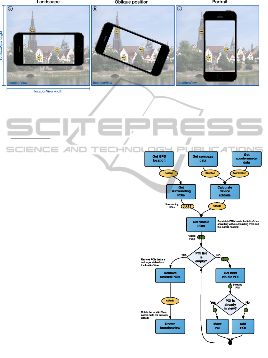
Figure 1: Examples of locationView depicting its characteristics.
in an oblique position. The vertical and horizon-
tal dimensions of the field of view are scaled pro-
portionally to the diagonal of the screen, such that
a new maximum field of view results with the size
of
p
width
2
+ height
2
pixels. Since the locationView
is placed centrally on the screen, the camera’s ac-
tual field of view is not distorted. Further, it can
be customized by rotating it contrary to the rotation
of the device. The calculated maximal field of view
is needed to efficiently draw POIs visible in portrait
mode, landscape mode, or any oblique position inbe-
tween.
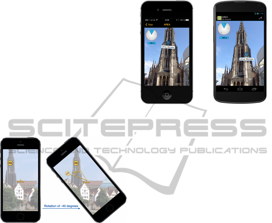
Fig. 1 presents an example illustrating the con-
cept of the locationView. Thereby, each sub-figure
represents one locationView. As one can see, a lo-
cationView is bigger than the display of the respec-
tive mobile device. Therefore, the camera’s field of
view must be increased by a certain factor such that
all POIs, which are either visible in portrait mode (cf.
Fig. 1c), landscape mode (cf. Fig. 1a), or any rotation
inbetween (cf. Fig. 1b), are drawn on the location-
View. For example, Fig. 1a shows a POI (on the top)
drawn on the locationView, but not yet visible on the
screen of the device in landscape mode. Note that this
POI is not visible for the user until he rotates his de-
vice to the position depicted in Fig. 1b. Furthermore,
when rotating the device from the position depicted in
Fig. 1b to portrait mode (cf. Fig. 1c), the POI on the
left disappears again from the field of view, but still
remains on the locationView.
The third reason for using the presented location-
View concept concerns performance. When the dis-
play has to be redrawn, the POIs already drawn on
the locationView can be easily queried and reused.
Instead of first clearing the entire screen and after-
wards re-initializing and redrawing already visible
POIs, POIs that shall remain visible, do not have to be
redrawn. Furthermore, POIs located outside the field
of view after a rotation are deleted from it, whereas
POIs that emerge inside the field of view are initial-
ized.
Fig. 2 sketches the basic algorithm used for real-
izing this locationView
2
.
Figure 2: Algorithm realizing the locationView (sketched).
2
More technical details can be found in a technical re-
port (Geiger et al., 2013)
Location-basedMobileAugmentedRealityApplications-Challenges,Examples,LessonsLearned
385

2.2 Architecture
The AREA architecture has been designed with the
goal to be able to easily exchange and extend its com-
ponents. The design comprises four main modules
organized in a multi-tier architecture and complying
with the Model View Controller pattern (cf. Fig. 3).
Lower tiers offer their services and functions by inter-
faces to upper tiers. In particular, the red tier (cf. Fig.
3) will be described in detail in Section 3, when dis-
cussing the differences regarding the development of
AREA on the iOS and Android platforms. Based on
this architectural design, modularity can be ensured;
i.e., both data management and various elements (e.g.,
the POIs) can be customized and extended on de-
mand. Furthermore, the compact design of AREA
enables us to build new mobile business applications
based on it as well as to easily integrate it with exist-
ing applications.
The lowest tier, called Model, provides modules
and functions to exchange the POIs. In this context,
we use both an XML- and a JSON-based interface to
collect and parse POIs. In turn, these POIs are then
stored in a global database. Note that we do not rely
on the ARML schema (ARML, 2013), but use our own
XML schema. In particular, we will be able to ex-
tend our XML-based format in the context of future
research on AREA. Finally, the JSON interface uses a
light-weight, easy to understand, and extendable for-
mat with which developers are familiar.
The next tier, called Controller, consists of two
main modules. The Sensor Controller is responsi-
ble for culling the sensors necessary to determine the
device’s location and orientation. The sensors to be
culled include the GPS sensor, the accelerometer, and
the compass sensor. The GPS sensor is used to deter-
mine the position of the device. Since we currently fo-
cus on location-based outdoor scenarios, GPS coordi-
nates are predominantly used. In future work, we ad-
dress indoor scenarios as well. Note that the architec-
ture of AREA has been designed to easily change the
way coordinates will be obtained. Using the GPS co-
ordinates and its corresponding altitude, we can cal-
culate the distance between mobile device and POI,
the horizontal bearing, and the vertical bearing. The
latter is used to display a POI higher or lower on the
screen, depending on its own altitude. In turn, the
accelerometer provides data for determining the cur-
rent rotation of the device, i.e., the orientation of the
device (landscape, portrait, or any other orientation
inbetween) (cf. Fig. 1). Since the accelerometer is
used to determine the vertical viewing direction, we
need the compass data of the mobile device to deter-
mine the horizontal viewing direction of the user as
well. Based on the vertical and horizontal viewing di-
rections, we are able to calculate the direction of the
field of view as well as its boundaries according to
the camera angle of view of the device. The Point of
Interest Controller (cf. Fig. 3) uses data of the Sen-
sor Controller in order to determine whether a POI
is inside the vertical and horizontal field of view. Fur-
thermore, for each POI it calculates its position on the
screen taking the current field of view and the camera
angle of view into account.
The uppermost tier, called View, consists of vari-
ous user interface elements, e.g., the locationView, the
Camera View, and the specific view of a POI (i.e., the
Point of Interest View). Thereby, the Camera View
displays the data captured by the device’s camera.
Right on top of the Camera View, the locationView
is placed. It displays POIs located inside the current
field of view at their specific positions as calculated
by the Point of Interest Controller. To rotate the lo-
cationView, the interface of the Sensor Controller is
used. The latter allows to determining the orienta-
tion of the device. Furthermore, a radar can be used
to indicate the direction in which invisible POIs are
located (cf. Fig. 9 shows an example of the radar).
Finally, AREA make use of libraries of the mobile
development frameworks themselves, which provide
access to core functionality of the underlying oper-
ating system, e.g., sensor access and screen drawing
functions (cf. Native Frameworks in Fig. 3).
3 EXPERIENCES WITH
IMPLEMENTING AREA ON
EXISTING MOBILE
OPERATING SYSTEMS
The kind of business application we consider uti-
lizes the various sensors of smart mobile devices, and
hence provides new kinds of features compared to tra-
ditional business applications. However, this signifi-
cantly increases complexity for application develop-
ers as well. This complexity further increases if the
mobile application shall be provided for different mo-
bile operating systems.
Picking up the scenario of mobile augmented re-
ality, this section gives insights into ways for effi-
ciently handling the POIs, relevant for the location-
View of our mobile augmented reality engine. In this
context, the implementation of the Sensor Controller
and the Point of Interest Controller are most interest-
ing regarding the subtle differences one must consider
when developing such an engine on different mobile
operating systems (i.e., iOS and Android).
WEBIST2014-InternationalConferenceonWebInformationSystemsandTechnologies
386
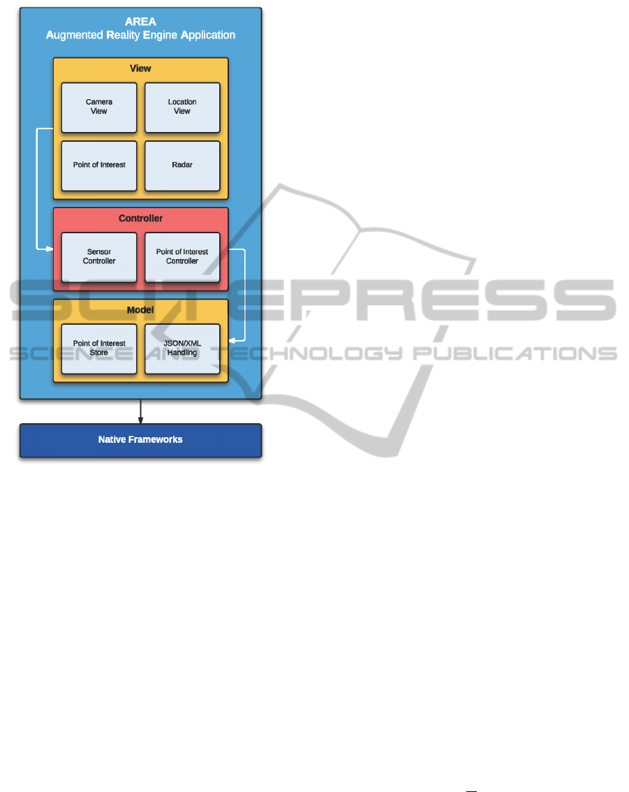
Figure 3: Multi-tier architecture of AREA.
In order to reach a high efficiency when displaying
or redrawing POIs on the screen, we choose a native
implementation of AREA on the iOS and Android
mobile operating systems. Thus, we can make use
of provided built-in APIs of these operating systems,
and can call native functions without any translation
as required in frameworks like Phonegap (Systems,
2013). Note that efficiency is very crucial for mo-
bile business applications (Corral et al., 2012) since
smart mobile devices rely on battery power. There-
fore, to avoid high battery usage by expensive frame-
work translations, only a native implementation is ap-
propriate in our context. Apart from this, most cross-
platform development frameworks do not provide a
proper set of functions to work with sensors (Schobel
et al., 2013). In the following, we present the imple-
mentation of AREA on both the iOS and the Android
mobile operating systems.
3.1 iOS Mobile Operating System
The iOS version of AREA has been implemented us-
ing the programming language Objective-C and iOS
Version 7.0 on Apple iPhone 4S. Furthermore, for de-
veloping AREA, the Xcode environment (Version 5)
has been used.
3.1.1 Sensor Controller
The Sensor Controller is responsible for culling the
necessary sensors in order to correctly position the
POIs on the screen of the smart mobile device. To
achieve this, iOS provides the CoreMotion and Core-
Location frameworks. We use the CoreLocation
framework to get notified about changes of the lo-
cation as well as compass heading. Since we want
to be informed about every change of the compass
heading, we adjusted the heading filter of the CoreLo-
cation framework accordingly. When the framework
sends us new heading data, its data structure contains
a real heading as well as a magnetic one as floats. The
real heading complies to the geographic north pole,
whereas the magnetic heading refers to the magnetic
north pole. Since our coordinates corresponds to GPS
coordinates, we use the real heading data structure.
Note that the values of the heading will become (very)
inaccurate and oscillate when the device is moved. To
cope with this, we apply a lowpass filter (Kamenetsky,
2013) to the heading in order to obtain smooth and ac-
curate values, which can then be used to position the
POIs on the screen. Similar to the heading, we can
adjust how often we want to be informed about loca-
tion changes. On one hand, we want to get notified
about all relevant location changes; on the other, ev-
ery change requires a recalculation of the surrounding
POIs. Thus, we deciced to get notified only if a dif-
ference of at least 10 meters occurs between the old
and the new location. Note that this is generally ac-
ceptable for the kind of applications we consider (cf.
Section 4.1). Finally, the data structure representing
a location contains GPS coordinates of the device in
degrees north and degrees east as decimal values, the
altitude in meters, and a time stamp.
In turn, the CoreMotion framework provides in-
terfaces to cull the accelerometer. The accelerometer
is used to calculate the current rotation of the device
as well as to determine in which direction the smart
mobile device is pointing (e.g., in upwards or down-
wards direction). As opposed to location and heading
data, accelerometer data is not automatically pushed
by the iOS CoreMotion framework to the application.
Therefore, we had to define an application loop that
is polling this data every
1
90
seconds. On one hand,
this rate is fast enough to obtain smooth values; on
the other, it is low enough to save battery power. As
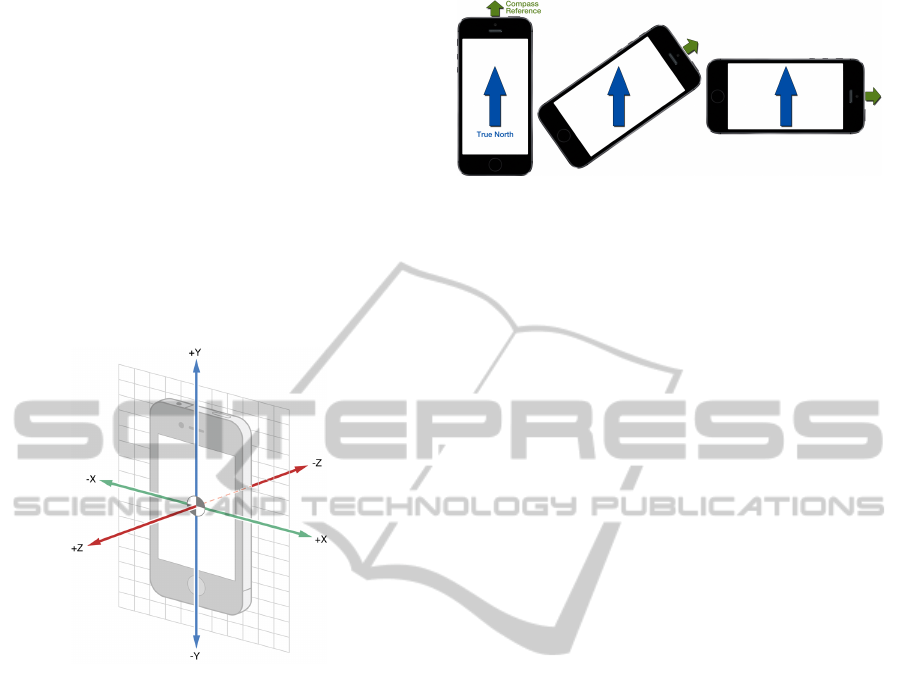
illustrated by Fig. 4, the data the accelerometer de-
livers consists of three values, i.e., the accelerations
in x-, y-, and z-direction ((Apple, 2013)). Since grav-
Location-basedMobileAugmentedRealityApplications-Challenges,Examples,LessonsLearned
387
ity is required for calculating in which direction a de-
vice is pointing, but we cannot obtain this gravity di-
rectly using the acceleration data, we had to addition-
ally apply a lowpass filter (Kamenetsky, 2013), i.e.,
the filter is used for being applied to the x-, y-, and
z-direction values. Thereby, the three values obtained
are averaged and filtered. In order to obtain the ver-
tical heading as well as the rotation of the device, we
then have to apply the following steps: First, by cal-
culating arcsin(z), we obtain a value between ±90
◦
and describing the vertical heading. Second, by cal-
culating arctan 2(−y, x), we obtain a value between 0
◦
and 359
◦
, describing the degree of the amount of the
rotation of the (Alasdair, 2011) of the device.
Figure 4: The three axes of the iPhone acceleration sensor
(Apple, 2013).
Since we need to consider all possible orientations
of the smart mobile device, we must adjust the com-
pass data accordingly. For example, assume that we
hold the device in portrait mode in front of us towards
the North. Then, the compass data we obtain indicate
that we are viewing in northern direction. As soon as
we rotate the device, however, the compass data will
change, although our view still goes to northern di-
rection. This is caused by the fact that the reference
point of the compass corresponds to the upper end of
the device. To cope with this issue, we must adjust
the compass data using the above presented rotation
calculation. When subtracting the rotation value (i.e.,
0
◦
and 359
◦
) from the compass data, we obtain the
desired compass value, still viewing in northern di-
rection after rotating the device (cf. Fig. 5).
3.1.2 Point of Interest Controller
As soon as the Sensor Controller has collected the re-
quired data, it notifies the Point of Interest Controller
at two points in time: (1) when detecting a new lo-
cation and (2) after having gathered new heading as
Figure 5: Adjusting the compass data to the device’s current
rotation.
well as accelerometer data. When a new location
is detected, we must determine the POIs in the sur-
rounding of the user. For this purpose, we use an ad-
justable radius (see Fig. 9 for an example of such an
adjustable radius). By using the latter, a user can de-
termine the maximum distance she has to the POIs
to be displayed. By calculating the distance between
the device and the POIs based on their GPS coordi-
nates (Bullock, 2007), we can determine the POIs lo-
cated inside the chosen radius and hence the POIs to
be displayed on the screen. Since only POIs inside
the field of view (i.e., POIs actually visible for the
user) shall be displayed on the screen, we must fur-
ther calculate the vertical and horizontal bearing of
the POIs inside the radius. Due to space limitation,
we cannot describe these calculations in detail, but
refer interested readers to a technical report (Geiger
et al., 2013). As explained in this report, the verti-
cal bearing can be calculated based on the altitudes of
the POIs and the smart mobile device (the latter can
be determined from the current GPS coordinates). In
turn, the horizontal bearing can be computed using
the Haversine formula (Sinnott, 1984) and applying it
to the GPS coordinates of the POI and the smart mo-
bile device. Finally, in order to avoid recalculations
of these surrounding POIs in case the GPS coordi-
nates do not change (i.e., within movings of 10m), we
must buffer data of the POIs inside the controller im-
plementation for efficiency reasons.
As a next step, the heading and accelerometer data
need to be processed when obtaining a notification
from the Sensor Controller (i.e., the application loop
mentioned in Section 3.1.1 has delivered new data).
Based on this, we can determine whether or not a
POI is located inside the vertical and horizontal field
of view, and at which position it shall be displayed
on the locationView. Recall that the locationView ex-
tends the actual field of view to a larger, orientation-
independent field of view (cf. Fig. 6). The first step is
to determine the boundaries of the locationView based
on sensor data. In this context, the heading data pro-
vides the information required to determine the di-
rection the device is pointing at. The left boundary
of the locationView can be calculated by determining
WEBIST2014-InternationalConferenceonWebInformationSystemsandTechnologies
388
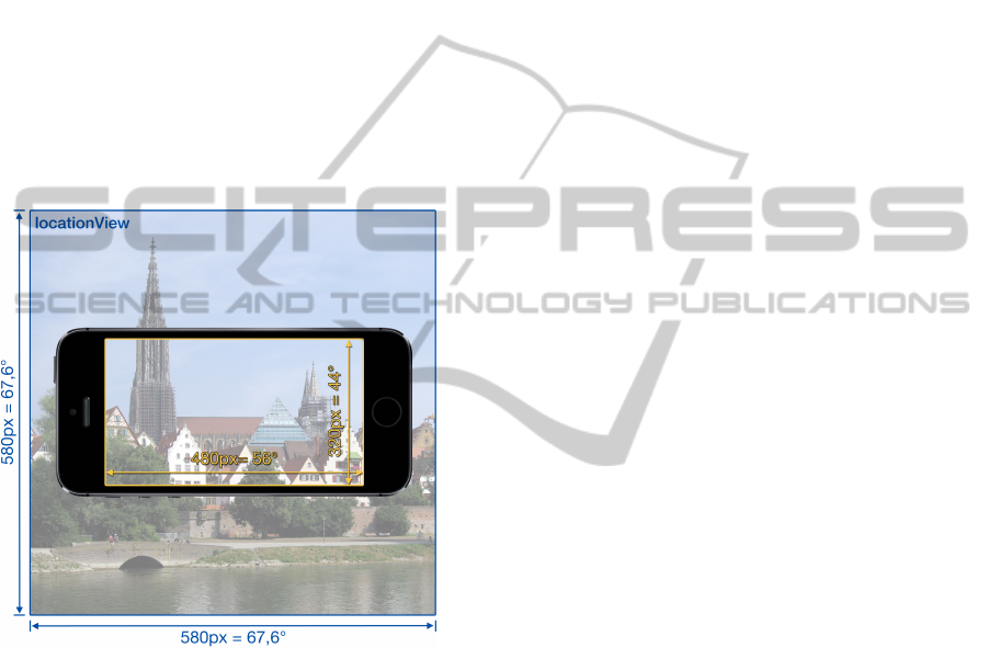
the horizontal heading and decreasing it by the half
of the maximal angle of view (cf. Fig. 6). The right
boundary is calculated by adding half of the maximal
angle of view to the current heading. Since POIs have
also a vertical heading, a vertical field of view must
be calculated as well. This is done analogously to the
calculation of the horizontal field of view, except that
the data of the vertical heading is required. Finally,
we obtain a directed, orientation-independent field of
view bounded by left, right, top, and bottom values.
Then we use the vertical and horizontal bearings of a
POI to determine whether it lies inside the location-
View (i.e., inside the field of view). Since we use the
concept of the locationView, we do not have to deal
with the rotation of the device at this point, i.e., we
can normalize calculations to portrait mode since the
rotation itself is handled by the locationView.
Figure 6: Illustration of the new maximal angle view and
the real one.
The camera view can be created and displayed ap-
plying the native AVFoundation framework. Using the
screen size of the device, which can be determined
at run time, the locationView can be initialized and
placed centrally on top of the camera view. As soon
as the Point of Interest Controller has finished its cal-
culations (i.e., it has determined the positions of the
POIs), it notifies the View Controller that organizes
the view components. The View Controller then re-
ceives the POIs and places them on the locationView.
Recall that in case of a device rotation, only the loca-
tionView must be rotated. As a consequence, the ac-
tual visible field of view changes accordingly. There-
fore, the Point of Interest Controller sends the rotation
of the device calculated by the Sensor Controller to
the View Controller, together with the POIs. Thus, we
can adjust the field of view by simply counterrotating
the locationView using the given angle. Based on this,
the user will only see those POIs on his screen, be-
ing inside the actual field of view. In turn, other POIs
will be hidden after the rotation, i.e., moved out of the
screen (cf. Fig. 1). Detailed insights into respective
implementation issues, together with well described
code samples, can be found in (Geiger et al., 2013).
3.2 Android Mobile Operating System
In general, mobile business applications should be
made available on all established platforms in order
to reach a large number of users. Hence, we devel-
oped AREA for the Android mobile operating system
as well (and will also make it available for Windows
Phone at a later point in time). This section gives
insights into the Android implementation of AREA,
comparing it with the corresponding iOS implemen-
tation. Although the basic software architecture of
AREA is the same for both mobile operating systems,
there are differences regarding its implementation.
3.2.1 Sensor Controller
For implementing the Sensor Controller, the pack-
ages android.location and android.hardware are used.
The location package provides functions to retrieve
the current GPS coordinate and altitude of the respec-
tive device, and is similar to the corresponding iOS
package. However, the Android location package ad-
ditionally allows retrieving an approximate position
of the device based on network triangulation. Par-
ticularly, if no GPS signal is available, the latter ap-
proach can be applied. However, as a drawback, no
information about the current altitude of the device
can be determined in this case. In turn, the hardware
package provides functions to get notified about the
current magnetic field and accelerometer. The latter
corresponds to the one of iOS, and is used to calcu-
late the rotation of the device. However, the heading
is calculated in a different way compared to iOS. In-
stead of obtaining it with the location service, it must
be determined manually. Generally, the heading de-
pends on the rotation of the device and the magnetic
field. Therefore, we create a rotation matrix using the
data of the magnetic field (i.e., a vector with three di-
mensions) and the rotation based on the accelerome-
ter data. Since the heading data depends on the ac-
celerometer as well as the magnetic field, it is rather
inaccurate. More precisely, the calculated heading is
strongly oscillating. Hence, we apply a lowpass fil-
ter to mitigate this oscillation. Note that this lowpass
filter is of another type than the one used in Section
3.1.1 for calculating the gravity.
Location-basedMobileAugmentedRealityApplications-Challenges,Examples,LessonsLearned
389
Moreover, as soon as other magnetic devices are
located nearby the actual mobile device, the heading
will be distorted. In order to notify the user about
the presence of such a disturbed magnetic field, lead-
ing to false heading values, we apply functions of the
hardware package. Another difference between iOS
and Android concerns the way the required data can
be obtained. Regarding iOS, location-based data is
pushed, whereas sensor data must be polled. As op-
posed to iOS, on Android all data is pushed by the
framework, i.e., application programmers rely on An-
droid internal loops and trust the up-to-dateness of
the data provided. Note that such subtle differences
between mobile operating systems and their develop-
ment frameworks should be well understood by the
developers of advanced mobile business applications.
3.2.2 Point of Interest Controller
Figure 7: Android specific rotation of POI and field of view.
Regarding Android, the Point of Interest Controller
works the same way as the one of iOS. However,
when developing AREA we had to deal with one par-
ticular issue. The locationView manages the visible
POIs as described above. Therefore, it must be able to
add child views (e.g., every POI generating one child
view). As described in Section 3.1, on iOS we simply
rotate the locationView to actually rotate the POIs and
the field of view. In turn, on Android, a layout con-
taining child views cannot be rotated in the same way.
Thus, when the Point of Interest Controller receives
sensor data from the Sensor Controller, the x- and y-
coordinates of the POIs must be determined in a dif-
ferent way. Instead of placing the POIs independently
of the current rotation of the device, we make use of
the degree of rotation provided by the Sensor Con-
troller. Following this, the POIs are rotated around
the centre of the locationView and we also rotate the
POIs about their centres (cf. Fig. 7). Using this ap-
proach, we can still add all POIs to the field of view
Figure 8: AREA’s user interface for iOS and Android.
of the locationView. Finally, when rotating the POIs,
they will automatically leave the device’s actual field
of view.
3.3 Comparison
This section compares the two implementations of
AREA on iOS and Android. First of all, it is note-
worthy that the features and functions of the two im-
plementations are the same. Moreover, the user inter-
faces realized for AREA on iOS and Android, respec-
tively, are the same (see Fig. 8).
3.3.1 Realizing the LocationView
The developed locationView with its specific features
differs between the Android and iOS implementations
of AREA. Regarding the iOS implementation, we
could realize the locationView concept as described
in Section 2.1. On the Android operating system,
however, not all features of this concept worked prop-
erly. More precisely, extending the actual field of
view of the device to the bigger size of the location-
View worked well. Furthermore, determining whether
or not a POI is inside the field of view, independent of
the rotation of the device, worked also well. By con-
trast, rotating the locationView with its POIs to adjust
the visible field of view as well as moving invisible
POIs out of the screen did not work as easy on An-
droid as expected. As particular problem in the given
context, a simple view on Android must not contain
any child views. Therefore, on Android we had to
use the layout concept for realizing the described lo-
cationView. However, simply rotating a layout does
not work on all Android devices. For example, on
a Nexus 4 device this worked well by implementing
the algorithm in exactly the same way as on iOS. In
WEBIST2014-InternationalConferenceonWebInformationSystemsandTechnologies
390

turn, on a Nexus 5 device this led to failures regard-
ing the redraw process. When rotating the layout on
the Nexus 5, the locationView is clipped by the cam-
era surface view, which is located behind our loca-
tionView. As a consequence, to ensure that AREA is
compatible with a wider set of Android devices, run-
ning Android 4.0 or later, we made the adjustments
described in Section 4.2.
3.3.2 Accessing Sensors
Using sensors on the two mobile operating systems
is different as well. The latter concerns the access
to the sensors as well as their preciseness and relia-
bility. Regarding iOS, the location sensor is offering
the GPS coordinates as well as the compass heading.
This data is pushed to the application by the underly-
ing service offered by iOS. Concerning Android, the
location sensor only provides data of the current lo-
cation. Furthermore, this data must be polled by the
application. The heading data, in turn, is calculated by
the fusion of several motion sensors, including the ac-
celerometer and magnetometer. The accelerometer is
used on both platforms to determine the current orien-
tation of the device. However, the preciseness of data
provided differs significantly. Running and compiling
the AREA engine on iOS with iOS 6 results in very
reliable compass data with an interval of one degree.
Running and compiling the AREA engine with iOS 7,
however, leads to different results compared to iOS 6.
As advantage, iOS 7 enables a higher resolution of the
data intervals provided by the framework due to the
use of floating point data instead of integers. In turn,
the partial unreliability of the delivered compass data
is disadvantageous. Regarding iOS 7, compass data
started to oscillate within an interval when moving the
device. Therefore, we needed to apply a stronger low-
pass filter in order to compensate this oscillating data.
In turn, on Android the internal magnetometer, which
is necessary for calculating the heading, is vulnera-
ble to noisy sources (e.g., other devices, magnets, or
computers). Thus, it might happen that the delivered
data is unreliable and the application must wait until
more reliable sensor data becomes available.
Furthermore, for each sensor the corresponding
documentation on the respective operating system
should be studied in detail in order to operate with
them efficiently. In particular, the high number of
different devices running Android constitutes a chal-
lenge when deploying AREA on the various hard-
ware and software configurations of manufacturers.
Finally, we learned that Android devices are often af-
fected by distortions of other electronic hardware and,
therefore, the delivered data might be unreliable as
well.
Overall, the described differences demonstrate
that developing advanced mobile business applica-
tions, which make use of the technical capabilities of
modern smart mobile devices, is far from being trivial
from the viewpoint of application developers.
4 VALIDATION
This section deals with the development of business
applications with AREA and the lessons learned in
this context.
4.1 Developing Business Applications
with AREA
AREA has been integrated with several business ap-
plications. For example, one company uses AREA
for its application LiveGuide (CMCityMedia, 2013).
A LiveGuide can be used to provide residents and
tourists of a German city with the opportunity to ex-
plore their surrounding by displaying points of inter-
ests stored for that city (e.g., public buildings, parks,
places of events, or companies). When realizing such
business applications on top of AREA, it turned out
that their implementation benefits from the modular
design and extensibility of AREA. Furthermore, an
efficient implementation could be realized. In partic-
ular, when developing the LiveGuide application type,
only the following two steps were required: First, the
appearance of the POIs was adapted to meet the user
interface requirements of the respective customers.
Second, the data model of AREA was adapted to an
already existing one. On the left side of Fig. 9, we
show user interface elements we made in the context
of the LiveGuide applications. In turn, on the right
side of Fig. 9, we show the user interface elements
originally implemented for AREA.
4.2 Lessons Learned
This section discusses issues that emerged when de-
veloping business applications (e.g., LiveGuide) on
top of AREA. Note that we got many other practi-
cal insights from the use of AREA. However, to set a
focus, we restrict ourselves to two selected issues.
4.2.1 Updates of Mobile Operating Systems
As known, the iOS and Android mobile operating
systems are frequently updated. In turn, respective
updates must be carefully considered when devel-
oping and deploying an advanced mobile business
application like AREA. Since the latter depends on
Location-basedMobileAugmentedRealityApplications-Challenges,Examples,LessonsLearned
391
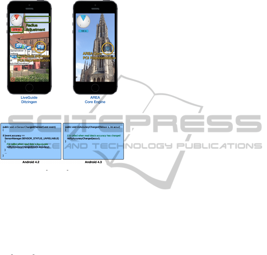
Figure 9: Typical adapted user interface provided by a
LiveGuide application.
Figure 10: SENSOR STATUS UNRELIABLE change in
Android 4.3.
the availability of accurate sensor data, fundamental
changes of the respective native libraries might af-
fect the proper execution of AREA. As example, con-
sider the following issue we had to cope with in the
context of an update of the Android operating sys-
tem (i.e., the switch from Android Version 4.2 to Ver-
sion 4.3). In the old version, the sensor framework
notifies AREA when measured data becomes unre-
liable. However, with the new version of the mo-
bile operating system, certain constants (e.g., SEN-
SOR STATUS UNRELIABLE) we had used were no
longer known on respective devices (cf. Fig. 10).
To deal with this issue, the respective constant had
to be replaced by a listener (cf. Fig. 10 onAccuracy-
Changed). As another example consider the release
of iOS 7, which led to a change of the look and feel of
the entire user interface. In particular, some of the
customized user interface elements in the deployed
version of the LiveGuide applications got hidden from
one moment to the other or did not react to user in-
teractions anymore. Thus, the application had to be
fixed. Altogether, we learned that adjusting mobile
applications due to operating system updates might
cause considerable efforts.
4.2.2 POI Data Format
Using our own proprietary XML schema instead
of applying and adapting the open source schema
ARML has its pros and cons. On one hand, we can
simply extend and modify this schema, e.g., to ad-
dress upcoming issues in future work. On the other,
when integrating AREA with the LiveGuide applica-
tion, we also revealed drawbacks of our approach. In
particular, the data format of POIs, stored in external
databases, differs due to the use of a non-standardized
format. Thus, the idea of ARML (ARML, 2013) is
promising. Using such a standardized format for rep-
resenting POIs from different sources should be pur-
sued. Therefore, we will adapt AREA to support this
standard with the goal to allow for an easy integration
of AREA with other business applications.
5 RELATED WORK
Previous research related to the development of a
location-based augmented reality application, which
is based on GPS coordinates and sensors running on
head-mounted displays, is described in (Feiner et al.,
1997) and (Kooper and MacIntyre, 2003). In turn, a
simple smart mobile device, extended by additional
sensors, has been applied by (K
¨
ah
¨
ari and Murphy,
2006) to develop an augmented reality system. An-
other application using augmented reality is described
in (Lee et al., 2009). Its purpose is to share me-
dia data and other information in a real-world envi-
ronment and to allow users to interact with this data
through augmented reality. However, none of these
approaches addresses location-based augmented real-
ity on smart mobile devices as AREA does. In par-
ticular, these approaches do not give insights into the
development of such business applications.
The increasing size of the smart mobile device
market as well as the technical maturity of smart
mobile devices has motivated software vendors to
realize augmented reality software development kits
(SDKs). Example of such SDKs included Wikitude
(Wikitude, 2013), Layar (Layar, 2013), and Junaio
(Junaio, 2013). Besides these SDKs, there are popu-
lar applications like Yelp (Yelp, 2013), which use ad-
ditional features of augmented reality to assist users
when interacting with their surrounding.
Only little work can be found, which deals with
the development of augmented reality systems in gen-
eral. As an exception, (Grubert et al., 2011) validates
existing augmented reality browsers. However, nei-
ther commercial software vendors nor scientific re-
sults related to augmented reality provide any insight
WEBIST2014-InternationalConferenceonWebInformationSystemsandTechnologies
392

into how to develop a location-based mobile aug-
mented reality engine.
6 SUMMARY & OUTLOOK
The purpose of this paper was to give insights into the
development of the core framework of an augmented
reality engine for smart mobile devices. We have fur-
ther shown how business applications can be imple-
mented based on the functionality of this mobile en-
gine. As demonstrated along selected implementation
issues, such a development is very challenging. First
of all, a basic knowledge about mathematical calcu-
lations is required, i.e., formulas to calculate the dis-
tance and heading of points of interest on a sphere in
the context of outdoor scenarios. Furthermore, deep
knowledge about the various sensors of the smart mo-
bile device is required from application developers,
particularly regarding the way the data provided by
these sensors can be accessed and processed. Another
important issue concerns resource and energy con-
sumption. Since smart mobile devices have limited
resources and performance capabilities, the points of
interest should be displayed in an efficient way and
without delay. Therefore, the calculations required to
handle sensor data and to realize the general screen
drawing that must be implemented as efficient as pos-
sible. The latter has been accomplished through the
concept of the locationView, which allows increasing
the field of view and reusing already drawn points of
interest. In particular, the increased size allows the
AREA engine to easily determine whether or not a
point of view is inside the locationView without con-
sidering the current rotation of the smart mobile de-
vice. In addition, all displayed points of interest can
be rotated easily.
We argue that an augmented reality engine like
AREA must provide a sufficient degree of modular-
ity to enable a full and easy integration with existing
applications as well as to implement new applications
on top of it. Finally, it is crucial to realize a proper
architecture and class design, not neglecting the com-
munication between the components. We have fur-
ther demonstrated how to integrate AREA in a real-
world business applications (i.e., LiveGuide) and how
to make use of AREA’s functionality. In this context,
the respective application has been made available in
the Apple App and Android Google Play Stores. In
particular, the realized application has shown high ro-
bustness. Finally, we have given insights into the dif-
ferences between Apple’s and Google’s mobile oper-
ating systems when developing AREA.
Future research on AREA will address the chal-
lenges we identified during the implementation of the
LiveGuide business application. For example, in cer-
tain scenarios the POIs located in the same direction
overlap each other, making it difficult for users to pre-
cisely touch POIs. To deal with this issue, we are
working on algorithms for detecting clusters of POIs
and offering a way for users to interact with these
clusters. In (Feineis, 2013), a component for on-the-
trail navigation in mountainous regions has been de-
veloped on top of AREA, which is subject of cur-
rent research as well. Furthermore, we are develop-
ing a marker-based augmented reality component in
order to integrate marker based with location based
augmented reality. Since GPS is only available for
outdoor location, but AREA should also for indoor
scenarios, we are working towards this direction as
well. In the latter context, we use Wi-Fi triangulation
to determine the device’s indoor position (Bachmeier,
2013). Second, we are experiencing with the iBea-
cons approach introduced by Apple.
Finally, research on business process management
offers flexible concepts, which are useful for enabling
proper exception handling in the context of mobile
applications as well (Pryss et al., 2012; Pryss et al.,
2013; Pryss et al., 2010). Since mobile augmented
reality applications may cause various errors (e.g.,
sensor data is missing), adopting these concepts is
promising.
REFERENCES
Alasdair, A. (2011). Basic Sensors in iOS: Programming
the Accelerometer, Gyroscope, and More. O’Reilly
Media.
Apple (2013). Event handling guide for iOS: Motion events.
[Online; accessed 10.12.2013].
ARML (2013). Augmented reality markup language.
http://openarml.org/wikitude4.html. [Online; ac-
cessed 10.12.2013].
Bachmeier, A. (2013). Wi-fi based indoor navigation in the
context of mobile services. Master Thesis, University
of Ulm.
Bullock, R. (2007). Great circle distances and bearings be-
tween two locations. [Online; accessed 10.12.2013].
Carmigniani, J., Furht, B., Anisetti, M., Ceravolo, P., Dami-
ani, E., and Ivkovic, M. (2011). Augmented reality
technologies, systems and applications. Multimedia
Tools and Applications, 51(1):341–377.
CMCityMedia (2013). City liveguide. http://liveguide.de.
[Online; accessed 10.12.2013].
Corral, L., Sillitti, A., and Succi, G. (2012). Mobile
multiplatform development: An experiment for per-
formance analysis. Procedia Computer Science,
10(0):736 – 743.
Location-basedMobileAugmentedRealityApplications-Challenges,Examples,LessonsLearned
393

Feineis, L. (2013). Development of an augmented reality
component for on the trail navigation in mountainous
regions. Master Thesis, University of Ulm, Germany.
Feiner, S., MacIntyre, B., H
¨
ollerer, T., and Webster, A.
(1997). A touring machine: Prototyping 3d mobile
augmented reality systems for exploring the urban en-
vironment. Personal Technologies, 1(4):208–217.
Fr
¨
ohlich, P., Simon, R., Baillie, L., and Anegg, H. (2006).
Comparing conceptual designs for mobile access to
geo-spatial information. Proc of the 8th Conf on
Human-computer Interaction with Mobile Devices
and Services, pages 109–112.
Geiger, P., Pryss, R., Schickler, M., and Reichert, M.
(2013). Engineering an advanced location-based aug-
mented reality engine for smart mobile devices. Tech-
nical Report UIB-2013-09, University of Ulm, Ger-
many.
Grubert, J., Langlotz, T., and Grasset, R. (2011). Aug-
mented reality browser survey. Technical report, In-
stitute for Computer Graphics and Vision, Graz Uni-
versity of Technology, Austria.
Junaio (2013). Junaio. http://www.junaio.com/. [Online;
accessed 11.06.2013].
K
¨
ah
¨
ari, M. and Murphy, D. (2006). Mara: Sensor based
augmented reality system for mobile imaging device.
5th IEEE and ACM Int’l Symposium on Mixed and
Augmented Reality.
Kamenetsky, M. (2013). Filtered audio demo.
http://www.stanford.edu/∼boyd/ee102/conv demo.pdf.
[Online; accessed 17.01.2013].
Kooper, R. and MacIntyre, B. (2003). Browsing the real-
world wide web: Maintaining awareness of virtual in-
formation in an AR information space. Int’l Journal
of Human-Computer Interaction, 16(3):425–446.
Layar (2013). Layar. http://www.layar.com/. [Online; ac-
cessed 11.06.2013].
Lee, R., Kitayama, D., Kwon, Y., and Sumiya, K. (2009).
Interoperable augmented web browsing for exploring
virtual media in real space. Proc of the 2nd Int’l Work-
shop on Location and the Web, page 7.
Paucher, R. and Turk, M. (2010). Location-based aug-
mented reality on mobile phones. IEEE Computer
Society Conf on Computer Vision and Pattern Recog-
nition Workshops (CVPRW), pages 9–16.
Pryss, R., Langer, D., Reichert, M., and Hallerbach, A.
(2012). Mobile task management for medical ward
rounds - the MEDo approach. Proc BPM’12 Work-
shops, 132:43–54.
Pryss, R., Musiol, S., and Reichert, M. (2013). Collabora-
tion support through mobile processes and entailment
constraints. Proc 9th IEEE Int’l Conf on Collabora-
tive Computing (CollaborateCom’13).
Pryss, R., Tiedeken, J., Kreher, U., and Reichert, M. (2010).
Towards flexible process support on mobile devices.
Proc CAiSE’10 Forum - Information Systems Evolu-
tion, (72):150–165.
Reitmayr, G. and Schmalstieg, D. (2003). Location based
applications for mobile augmented reality. Proc of the
Fourth Australasian user interface conference on User
interfaces, pages 65–73.
Robecke, A., Pryss, R., and Reichert, M. (2011).
Dbischolar: An iphone application for performing ci-
tation analyses. Proc CAiSE’11 Forum at the 23rd
Int’l Conf on Advanced Information Systems Engi-
neering, (Vol-73).
Schobel, J., Schickler, M., Pryss, R., Nienhaus, H., and
Reichert, M. (2013). Using vital sensors in mobile
healthcare business applications: Challenges, exam-
ples, lessons learned. Int’l Conf on Web Information
Systems and Technologies, pages 509–518.
Sinnott, R. (1984). Virtues of the haversine. Sky and tele-
scope, 68:2:158.
Systems, A. (2013). Phonegap. http://phonegap.com. [On-
line; accessed 10.12.2013].
Wikitude (2013). Wikitude. http://www.wikitude.com.
[Online; accessed 11.06.2013].
Yelp (2013). Yelp. http://www.yelp.com. [Online; accessed
11.06.2013].
WEBIST2014-InternationalConferenceonWebInformationSystemsandTechnologies
394
