
A Lightweight Framework for Graphical Editors on Android Devices
Thomas Buchmann and Patrick Pezoldt
Chair of Applied Computer Science I, University of Bayreuth, Universitaetsstrasse 30, 95440 Bayreuth, Germany
Keywords:
Mobile Development, Graphical Editors, Gesture Support.
Abstract:
During the last few years, mobile devices and corresponding applications gain more and more attention. The
number of users of mobile devices like phones or tablets has been increasing dramatically. Thus, software
engineering for mobile applications becomes more and more important. While development frameworks for
such devices provide rich support for sophisticated input mechanisms like gestures, etc., they lack support
for graphical editors. In this paper, we present a lightweight framework which fills this gap. As a running
example, we present editors for UML class diagrams and activity diagrams which have been built using our
framework.
1 INTRODUCTION
Over the last few years, we observe an increasing pop-
ularity of touch-enabled devices. Smart phones nowa-
days have even more processing power than desktop
computers had a couple of years ago. Many people
are now equipped with smart phones or tablets and
mobile applications which make their every day lives
easier. But not only for personal use, but also for pro-
fessionals, smart phones and tablets are very useful.
Model-driven software engineering (V
¨
olter et al.,
2006) is a discipline which evolved during the last
decade. A wide variety of different tools exist, which
support the modeler during the development process.
Since model-driven software development is not tied
to a special software development methodology, these
tools usually can be used with any development pro-
cess.
Agile model driven development (AMDD) (Am-
bler, 2002) applies commonly known principles and
practices from traditional source code based agile
software development to model-driven development.
In his book (Ambler, 2002), Scott W. Ambler states,
that agile modeling (AM) asks to use the simplest
tools possible (e.g. papers and whiteboards). Com-
plex modeling tools should only be used, when they
provide the best value possible.
However, sketches drawn on papers or white-
boards have to be distributed to all involved team
members, e.g. by scanning or photographing the re-
sult. This raises several problems. While in source
code based approaches, where diagrams are only
used for documentation purposes, a photograph of
a whiteboard sketch might be enough, model-driven
approaches demand for models as first class entities.
Thus, every diagram that has been sketched on a
whiteboard or on a piece of paper has to be redone
in the respective modeling tool, which results in an
additional overhead. Furthermore, sketches on white-
boards or papers are often missing some essential de-
tails like role names or cardinalities of associations
for example. Usually these errors are fixed at a later
time, when the sketch is redone with the respective
modeling tool.
Modern devices are also equipped with HDMI
video output and can therefore be easily attached to
big TV screens or beamers. This motivated us to
add sketching capabilities to our UML-based model-
ing environment called Valkyrie (Buchmann, 2012b;
Buchmann, 2012a). This approach provides several
advantages: (1) a device running our tool might re-
place papers or whiteboards in agile modeling pro-
cesses as sketches directly result in corresponding
model instances. No manual redrawing of whiteboard
sketches in a modeling tool is required. (2) Since the
tool follows common UML standards, inconsistencies
like missing role names or cardinalities are immedi-
ately reported to the user and thus can be fixed right
away. However, when creating the extension to our
tool, we observed that the Android SDK lacks sup-
port for creating graphical editors.
Our contribution in this paper is a lightweight
framework which aids developers in creating touch-
enabled graphical editors for Android devices. In
81
Buchmann T. and Pezoldt P..
A Lightweight Framework for Graphical Editors on Android Devices.
DOI: 10.5220/0004984300810089
In Proceedings of the 9th International Conference on Software Engineering and Applications (ICSOFT-EA-2014), pages 81-89
ISBN: 978-989-758-036-9
Copyright
c
2014 SCITEPRESS (Science and Technology Publications, Lda.)

general, graphical editors are used to visualize graph-
based data structures. In software engineering pro-
cesses, graph-based structures are the underlying data
model for various use cases, e.g. petri nets, process
modeling or UML modeling just to name a few. Fur-
thermore, we also present a small example of how to
use our framework for a touch-enabled UML class di-
agram editor.
The paper is structured as follows: In the next sec-
tion, we discuss related work. An overview about
our framework is given in section 3. In section 4, we
demonstrate our framework by presenting cutouts of
the code of an UML class diagram editor which we
built, while section 6 concludes the paper.
2 RELATED WORK
To the best of our knowledge, there is no framework
for Android devices at the time this paper was written
which aids developers when building touch-enabled
graphical editors. Of course, there are a lot of WYSI-
WYG / Visual editors available which aid developers
in designing user interfaces for their apps, but those
tools do not provide support for building graphical ed-
itors. Thus, we decided to compare our framework to
existing ones which are designed for regular desktop
applications (without touch support).
Graphical Editing Framework (GEF). GEF
1
is a
framework which supports interactive diagrams and
graphs. It is directly integrated into the Eclipse plat-
form. Its core architecture strictly follows the MVC
design pattern. The graphical editing framework is a
generic framework which can be used to build graph-
ical editors for arbitrary Java models. Basically, the
framework is composed from three different build-
ing blocks: (1) Draw2D - a lightweight framework
used to display figures on SWT basis, (2) Zest - a vi-
sualization toolkit based on Draw2D which is used
to combine Java model elements and Draw2D dia-
grams and (3) GEF - a model-view-controller frame-
work which is also based on Draw2D and which pro-
vides an API for interactive functions, like Drag and
Drop, Undo/Redo capabilities, etc. While it does not
provide native support for touch-enabled devices, re-
cently two projects emerged which address input of
diagrams using sketching techniques (Sangiorgi and
Barbosa, 2010; Scharf, 2013). While (Sangiorgi and
Barbosa, 2010) and (Scharf, 2013) realize an a poste-
riori integration of sketching capabilities into an exist-
ing framework for building graphical editors (GEF),
1
http://www.eclipse.org/gef
our approach aims at an a priori combination of ges-
tures and such a framework.
Graphical Modeling Framework (GMF). The
Graphical Modeling Framework (GMF) (Gronback,
2009) is the model-driven extension of GEF. The
added value compared to GEF is that basic graphi-
cal editors may be created without writing a single
line of Java code. GMF uses models to describe the
graphical primitives and the tool palette of the graph-
ical editor. Another model is used to link model ele-
ments, graphical elements and their respective tools.
This model acts as a basis for the Xpand-based code
generator. While this approach works well for simple
editors, manual adjustments /extensions of the gener-
ated code are needed in many cases (Buchmann et al.,
2007; Buchmann, 2012b). Furthermore GMF is not
as generic as GEF as it requires Ecore-based (Stein-
berg et al., 2009) semantic models. While our frame-
work presented in this paper is more general, as it al-
lows for any Java-based model, we successfully ap-
plied it to Ecore-based models as well.
Graphiti. Graphiti
2
is another Eclipse project,
which provides a graphical tooling infrastructure.
Similar to GMF its primary purpose is to provide
graphical representations fo EMF models, but nev-
ertheless it also works for Java-based objects on the
domain side as well. In contrast to GMF, it does not
provide a model-driven approach as it comes with a
plain Java API for building graphical tools. While
both GEF and GMF are intended to be used within the
Eclipse environment, Graphiti provides the option to
support different platforms. Just like the above men-
tioned frameworks, Graphiti also does not provide na-
tive support for touch-enabled devices.
Sirius. Sirius
3
is another Eclipse based project,
which empowers developers to build graphical editors
for domain specific languages. Like GMF it leverages
model-based architecture engineering by providing a
generic workbench that could easily be tailored to fit
specific needs. In contrast to GMF, the description
of a Sirius modeling workbench is dynamically inter-
preted by a run-time within the Eclipse IDE. Again,
also Sirius does not provide native support for touch-
enabled devices.
Upgrade. UPGRADE (B
¨
ohlen et al., 2002b;
B
¨
ohlen et al., 2002a) is another Java-based frame-
work which is used for building graph-based inter-
2
http://www.eclipse.org/graphiti
3
http://www.eclipse.org/sirius
ICSOFT-EA2014-9thInternationalConferenceonSoftwareEngineeringandApplications
82

active tools. Primarily it was designed to be used
as a visual front-end for PROGRES (Sch
¨
urr, 1996)
models. It puts focus on reusability and customiz-
ability, decoupling of application logic and user in-
terface, platform independence and many more. Plat-
form independence is achieved by using the Java pro-
gramming language. While the other frameworks dis-
cussed in this section are also written in Java, they
contain a lot of dependencies to the Eclipse work-
bench and their SDKs which make it impossible to
use them on Android. UPGRADE on the other hand
is independent from any IDE, but it turned out that
the framework is outdated and development activities
have been stopped a long time ago.
Web-based Approaches. In the past few years,
web-based approaches for graphical editors have
emerged. Gordon et al. (Gordon et al., 2005) present
a framework for light-weight web-based visual
applications. However, while a web-based graphical
editor could be used on any device which is capable
of running a browser, the approach presented by
Gordon et al. also misses support for gestures.
All of the approaches mentioned above provide
flexible support to create graphical editors for arbi-
trary models. The major drawback of all frameworks
in the context of this paper is, that they do not work on
Android devices and moreover, they do not provide
native support for sophisticated input mechanisms,
like gestures.
3 FRAMEWORK OVERVIEW
The basic design decision when developing a frame-
work for graphical diagram editors is which functions
should be encapsulated and which ones should be
implemented by the developers using it. The main
goal is to encapsulate as many functions as possi-
ble while providing developers with the freedom to
design corresponding editors according to their spe-
cific needs. Since the framework is targeted towards
building graphical editors for Android-powered de-
vices, they should be controlled using gestures. In
general, graphical editors are used to display nodes
and edges of a graph. The graphical representation
of those nodes and edges differs according to the ap-
plication domain and the respective visual language.
Thus, developers using our framework should be able
to specify the following:
Gestures. Specify all gestures which should be avail-
able to control the final editor.
Actions. Which actions should be executed once a
predefined gesture is performed.
Nodes. All visual elements which are used to display
different node types of the graph.
Edges. All visual elements which are used to display
the graph’s edge types.
On the other hand, certain operations which are
common for all types of graphical editors may be en-
capsulated within the framework, like e.g. moving
elements, zooming, scrolling, etc. Our framework en-
capsulates the following operations:
1. Drawing / editing nodes
2. Drawing / editing edges and their labels
3. Gesture processing
4. Zooming
5. Scrolling
6. Undo / redo of editing operations
7. Persistency mechanisms
8. Consistency with the Android SDK in terms of the
app life-cycle
In the following, we are going to discuss the major
building blocks of our framework in detail: visual el-
ements, gesture processing, undo/redo management,
and persistency.
3.1 Visual Elements
3.1.1 Shapes and Figures
Visual representation of nodes and edges is the most
important task of a graphical editor. When creating a
generic framework aiding the development of graph-
ical editors, only a few assumptions concerning the
shapes of the visual elements can be made. As a
consequence, we chose an approach which allows as
much flexibility as possible. As the visual elements
are directly rendered on the visible user interface of
the app, we had to pick the appropriate rendering
technique first. Basically, the Android SDK supports
two different approaches: (1) The graphical element
is rendered into a view which is part of the layout
(the Android run-time takes care of the rendering in
this case). (2) The graphical element is rendered di-
rectly to the UI using a canvas (manual control about
the rendering is possible here). Furthermore there are
two different ways of how to create complex visual
objects when working with the canvas: (1) Visual ele-
ments may be composed from graphical primitives or
(2) visual elements may be represented using bitmaps.
ALightweightFrameworkforGraphicalEditorsonAndroidDevices
83
While using elements composed from graphical prim-
itives requires less processing power and memory re-
sources, it is not feasible for complex objects. Using
bitmaps provides benefits in terms of allowing trans-
parency, possibility of matrix transformations and an
easy implementation. Bitmaps may contain transpar-
ent areas and such allow to display circles for exam-
ple. As a result, creating complex visual elements is
transferred to standard bitmap processing tools, like
e.g. Gimp
4
, which are perfect for this task. Images
are stored in an Android resource which can easily
be loaded into a bitmap during runtime. Further-
more, bitmaps may be rendered using a transforma-
tion matrix. Thus, transformations like rotation, trans-
lation or scaling can easily be applied. The Android
SDK provides a special extension to bitmap images –
NinePatchDrawable – which allows context-sensitive
scaling, i.e. areas near the image boundaries are du-
plicated during scaling while unmarked areas are not
affected. Within the Android SDK, a NinePatchDraw-
able is used for example for buttons.
AbstractElement
matrix : Matrix
Container
npd : NinePatchDrawable
1
0.. *
Text
text : String
Shape
bmp : Bitmap
npd : NinePatchDrawable
Vertex
Figure 1: Cutout of the class diagram responsible for han-
dling visual elements.
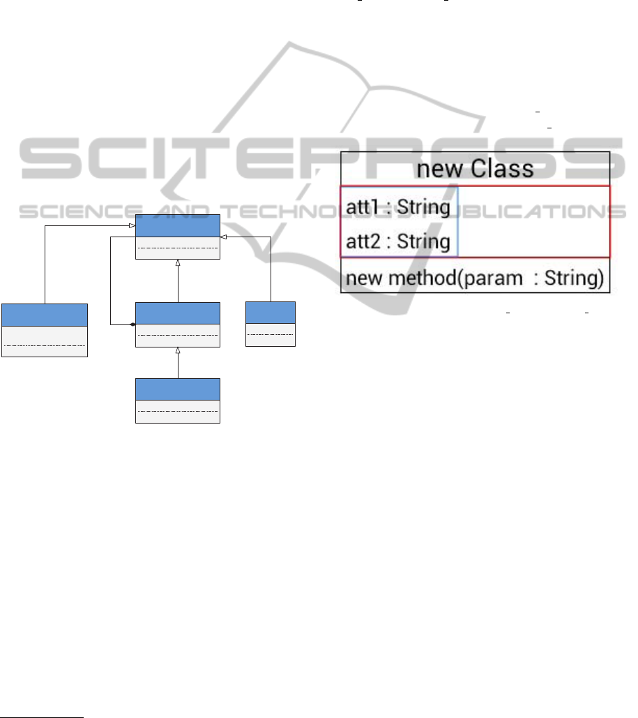
Figure 1 depicts a class diagram which contains
the structure of the visual elements representing nodes
as provided by our framework. Developers working
with our framework create visual elements by creat-
ing images and loading them. Furthermore, elements
may be composed hierarchically into an arbitrary tree
structure. The alignment of elements may be speci-
fied by layout information. The class diagram in Fig-
ure 1 contains a class Container which serves as a con-
tainer for child elements, while Vertex is the root el-
ement. Shape is used as a container for the (bitmap)
image and Text is the container for string literals. The
hierarchical structure of visual elements is modelled
using the composite association between Container
and AbstractElement. Vertex is a dedicated Container
4
http://www.gimp.org
which is the root of the containment hierarchy and
which is directly rendered onto the canvas of the app,
while Shape and Text represent the leaves.
Besides child elements, a Container may also
have a bitmap or a NinePatchDrawable as background
which are scaled to match the correct size of the vi-
sual element. The scaling behavior depends on the
layout information which offers a distinction between
wrap content and fill parent when scaling along x and
y directions. While the first one is used to match the
container’s size according to the size of its contained
children, the latter one is used to fit the container’s
size to its parent Container. Figure 2 depicts the dif-
ferences of both mechanisms. While the blue box in
the attribute section of the class depicted in Figure 2
symbolizes the scaling effect of wrap content, the red
box marks the result when choosing fill parent.
Figure 2: Difference between wrap content and fill parent.
The alignment (either horizontally or vertically)
of the contained elements is also part of the con-
tainer’s layout information. Furthermore a container
has a minimum size which avoids the visual element
to shrink in case its content is deleted.
3.1.2 Diagram Links and Decorators
Similar to shapes that are used to visualize nodes, the
diagram links that depict edges may have a different
visual appearance – which is also defined by the de-
veloper – according to the application domain. When
creating diagram links, several different aspects need
to be taken into account:
Line Properties: color and thickness of the line as
well as the visualization kind (solid, dashed, dot-
ted, etc.).
Anchor Points: An anchor point is a point which
serves as an interconnection between the visual
element representing a node and the link object.
Bend Points: A bend point of a link needs to satisfy
certain requirements, like the ability to be moved.
End Decorators: End decorators are custom shapes
which are located at the corresponding ends of the
link, e.g. arrow heads.
ICSOFT-EA2014-9thInternationalConferenceonSoftwareEngineeringandApplications
84
Labels: A link may contain different labels which
are used to display arbitrary string literals.
The Android Canvas object provides a native
method drawPath(), which we used to display the
links. Thus, the link and all of its bend points needs
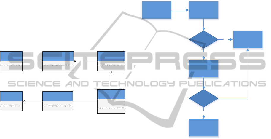
to be transformed into a Path object. Figure 3 de-
picts a simplified class diagram which is responsible
for handling links and decorators. A Link object is al-
ways connecting two Vertex objects and may contain
an arbitrary number of BendPoints. In our case, an
end Decorator is a specialized BendPoint.
Our framework offers a set of different predefined
end decorators as well as the possibility to create new
ones. As a result, the usage of elements visualizing
edges is very easy and can be achieved with only a
few lines of code.
Vertex Link
path : Path
updatePath() : void
BendPoint
Decorator
bitmapId : int
matrix : Matrix
Text
text : String
LinkText
2..2 0..* 0..1 0..*
0..1
0..1
Figure 3: Simplified class diagram responsible for handling
links and decorators.
3.2 Gestures
All diagram editors which may be created using our
framework should be controlled using gestures. As
a consequence, a core requirement is that the frame-
work supports developers during this task as much as
possible. Furthermore common, predefined gestures
are encapsulated within the framework and are thus
common for all editors:
• Zooming
• Reset zoom factor
• Scrolling
• Move diagram nodes and links
• Select diagram nodes and links
• Delete diagram nodes and links
• Edit diagram nodes and links
• Connect nodes using links
Basically, the Android SDK provides two differ-
ent ways how gesture recognition may be handled in
an app. It provides an app (GestureBuilder) which al-
lows to draw and save gestures which can then be used
to compare the recognition result with the currently
drawn one. The comparison is done automatically by
the framework and quickly provides a result. Alter-
natively, the developer can decide to not use the au-
tomatical recognition which requires more program-
ming effort, but is much more flexible. The best ap-
proach is to use the automatic recognition whenever
possible, and to use the manual recognition only in
cases where the automatic recognition fails. This pro-
cess is sketched in figure 4.
Current Gesture
Automatic
Recognition
Possible
success Execute Gesture
Start Manual
Recognition
success
Discard Gesture
yes
no
no
yes
Figure 4: Gesture recognition process.
While the automatic gesture recognition provided
by Android is suitable for standard apps, gestures
in diagram editors might become much more diffi-
cult to handle. In general, when using the automatic
recognition, only one axis (x or y direction) is use-
able for gestures as the other one is automatically re-
served for scrolling purposes. It only raises one event
OnGesturePerformedListener which indicates a com-
plete gesture. The resulting gesture object can be
passed to the recognition algorithm. The Android
SDK provides another listener (OnGestureListener)
which provides a greater flexibility. It has three dif-
ferent call-backs which indicate start and stop and all
intermediate points of a gesture. The draw-back is
that composite gestures have to be assembled manu-
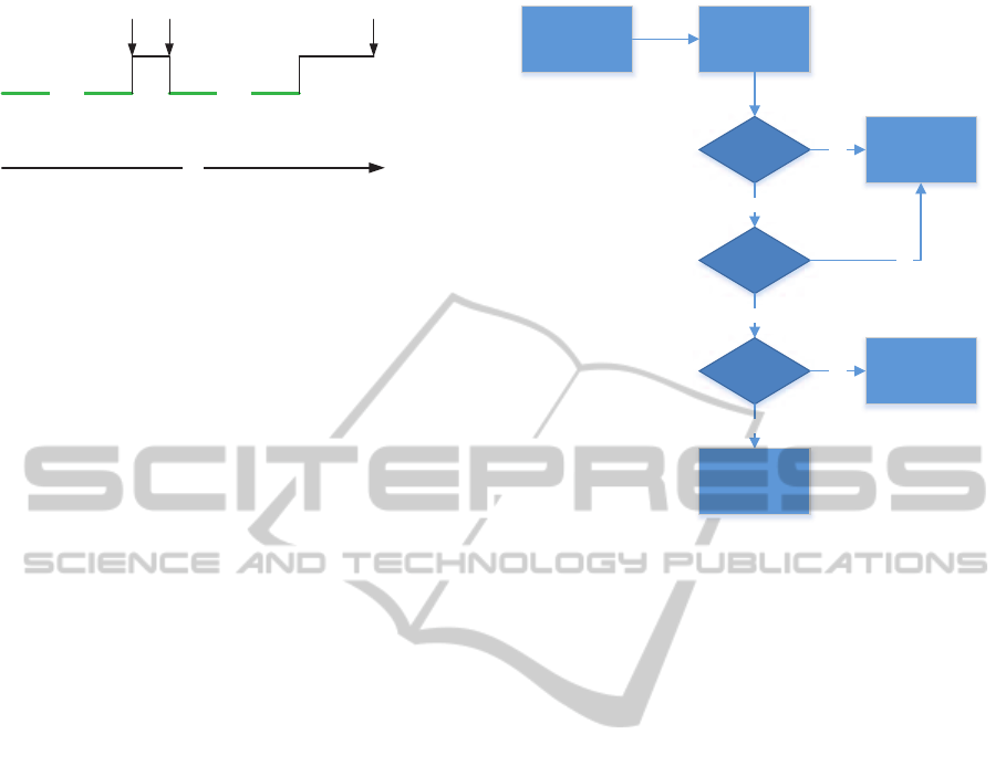
ally. To this end, our framework provides a listener
thread which can be configured with custom timeout
values. As long as the timeout is not raised, all ges-
tures performed are considered to be part of one sin-
gle composite gesture (c.f. Figure 5). We chose to use
the second gesture listener, since it allows to also im-
plement instant gestures, like moving, zooming etc.
which are used in resulting editors.
ALightweightFrameworkforGraphicalEditorsonAndroidDevices
85
Time
Gesture
drawn
Gesture
drawn
gesture end event
event for
new gesture part
timeout – gesture
thread ends
Figure 5: Gesture recognition process.
3.2.1 Gesture Recognition
After a gesture has been recorded, it needs to be inter-
preted. In our framework, the abstract class Gestur-
eRecognizer is responsible for this task. Framework
users have to inherit from this class and put their cus-
tom behavior into the corresponding method bodies.
The standard implementation of the GestureRecog-
nizer passes gestures to the Android recognition algo-
rithm and returns corresponding results, if the predic-
tion score exceeds a predefined threshold – the ges-
tures are ignored otherwise. If the GestureRecog-
nizer is not able to identify the gesture, a check is
performed, if a connection between two visual ele-
ments was made. Regarding connections, a distinc-
tion between gestures for solid and dashed connec-
tions is made and the gesture with all affected visual
elements is passed to the GestureMapping object for
further processing. In case there is no connection,
a check has to be performed if the user intended to
delete diagram elements. Figure 6 depicts the chain of
responsibility during gesture handling in our frame-
work.
3.3 Undo / Redo Management
Nowadays, almost every editor provides means for the
end users to record editing operations which can be
undone or redone. Thus, our framework incorporates
mechanisms to allow developers to build editors with
undo/redo functionality. To this end, all editing op-
erations are wrapped into actions implementing our
IAction interface. The interface provides the meth-
ods execute() and unexecute() respectively. While ex-
ecute() performs the desired action (e.g. creating a
new object), unexecute() resets the editor in its previ-
ous state. All actions are stored on an undo-stack and
thus may be undone in the correct order. Our frame-
work distinguishes between regular actions, compos-
ite actions (like moving) and actions which can not be
undone like zooming or scrolling (as these actions do
not change the state of the editor). Once a correspond-
ing action is undone, it is pushed onto the redo-stack,
while redoing an action has the opposite effect. As
soon as a new action is pushed onto the undo-stack,
Gesture Performed GestureRecognizer
recognized GestureMapping
isConnection
yes
no
no
yes
isDeleteGesture RemoveAction
Discard Gesture
yes
no
Figure 6: Chain of responsibility during gesture recogni-
tion.
the redo-stack is cleared since all actions stored in the
redo-stack might not be sensible any more.
4 EXAMPLE
This section demonstrates the creation of a graphical
diagram editor using our framework. We demonstrate
that only a few steps are required to create a touch-
enabled UML class diagram editor. We use the Ges-
tureBuilder app provided by Android to record the
gestures which should be used in the class diagram
editor. The first task is to inherit from the follow-
ing abstract classes and implement the corresponding
methods:
GestureRecognizer is responsible for recognizing
the gestures.
DrawableFactory is used to create the visual ele-
ments.
GestureMapping is used to map gestures and visual
elements and the corresponding editor actions re-
spectively.
EditorsActivity is used to assemble the other classes
and to provide the UI of the editor. Extensions of
the user interface are possible in this class.
Table 1 shows a cutout of different gestures and
their mapping to corresponding editor actions used in
our example. Please note that the drawing direction of
ICSOFT-EA2014-9thInternationalConferenceonSoftwareEngineeringandApplications
86
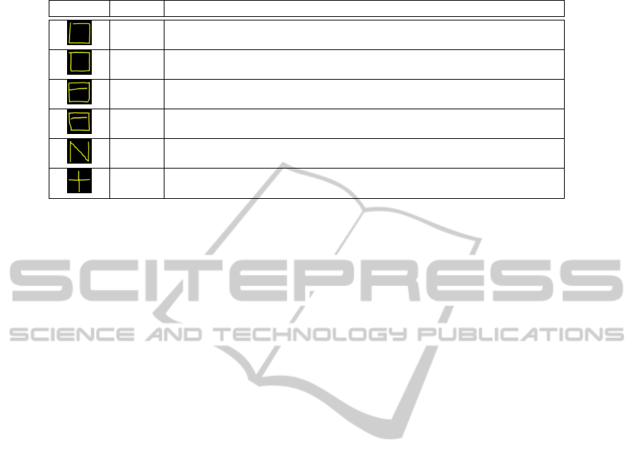
Table 1: Gestures used for the sample class diagram editor.
Gesture Name Description
square Create new class
square Create new class, gesture performed in opposite direction
square Create new class, multi-part gesture
square Create new class, multi-part gesture performed in opposite direction
n Create new interface
plus Add attributes and methods to classes / interfaces
gestures is crucial. To this end, we performed gestures
like the square both clockwise and counter-clockwise.
Our framework offers the possibility to deal with
miss-interpretations of gestures. E.g. the plus gesture
was recognized with a high probability even if only
one line was drawn with the standard gesture recog-
nition. Thus, we added a second test, if the gesture
in fact consists of two lines with an intersection. Af-
ter a positive recognition, the corresponding gesture is
handed over to the gesture mapping for interpretation.
The DrawableFactory is used to create all visual el-
ements. A new subclass ClassDiagFactory is created
for our sample editor. The new class contains factory
methods for visual elements which are called from
the corresponding GestureMapping class. E.g. to cre-
ate new classes in our class diagram editor, a method
public Vertext createClass() is added to the ClassDi-
agFactory. Each factory method, which creates visual
elements has to return a Vertex. Our framework al-
ready provides factory methods to create connections
between visual elements. This method needs the two
Vertices which are connected by the line as well as
start and end anchor points and the corresponding line
style.
The GestureMapping class is used to interpret rec-
ognized gestures and assign editor specific actions
to them. Again, we created a new subclass Class-
DiagGestureMapping and implemented the abstract
methods which are used to interpret gestures for vi-
sual elements and connections between them.
The EditorsActivity class is used to connect the
classes mentioned above and to modify the user inter-
face of our class diagram editor app. In order to use
the class diagram editor with our model-driven de-
velopment toolchain Valkyrie(Buchmann, 2012b), we
use Eclipse UML2 as data model. The corresponding
methods are also implemented in the ClassDiagEditor-
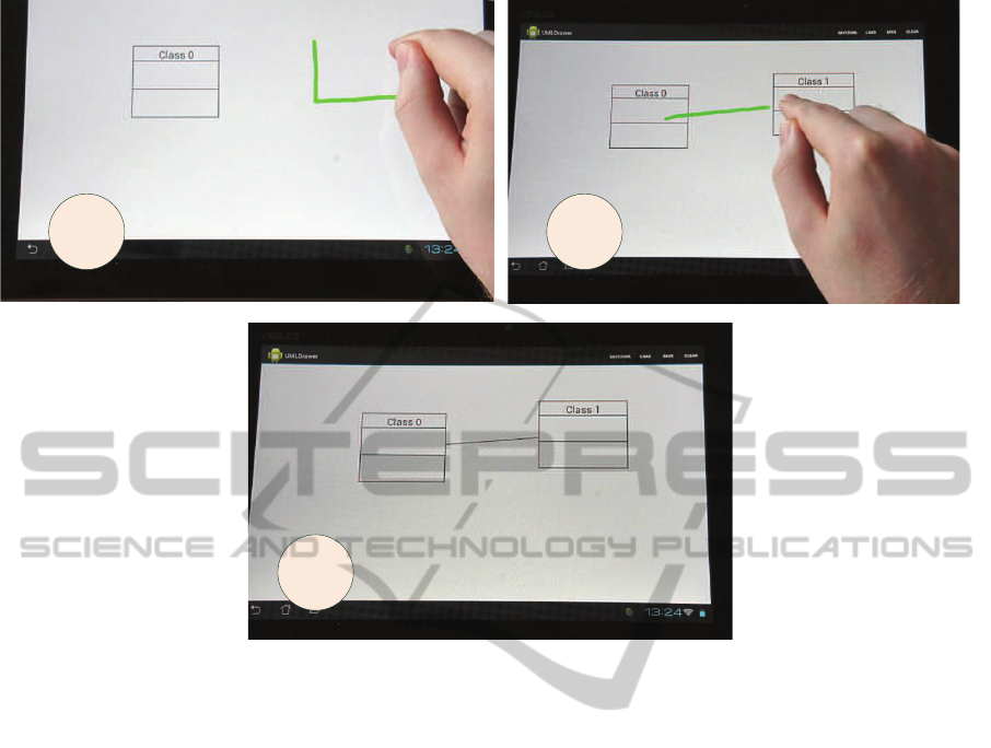
sActivity subclass. Figure 7 depicts the resulting class
diagram editor in action. In (1) the gesture (square)
for creating a new class is performed. After the ges-
ture has been recognized and interpreted, the corre-
sponding class and the visual representation is added.
In the next step (2), an association between the two
classes depicted in Fig. 7 is created by performing
the association gesture. The final result is shown in
(3).
5 DISCUSSION
In a recent project (Buchmann, 2012a), we investi-
gated the usage of touch-enabled devices in software
engineering processes. To this end, we created a
graphical editor for UML class diagrams from scratch
on an android device. Building such editors is a te-
dious and error-prone task, especially when integrat-
ing gesture support. For this reason, we developed the
framework presented in this paper, allowing users to
abstract from lower-level implementation issues. As
a consequence, the creation of gesture-enabled graph-
ical editors on android devices is facilitated consider-
ably. While the framework is still under development,
it is evident that even in its current state it provides an
added value for developers.
Typically, mobile devices are equipped with small
screens compared to desktop computers. While they
provide similar screen resolutions, it is obvious that
the content is displayed in a much smaller size, and
thus, is harder to read. Furthermore, diagrams tend
to become very large. As a consequence, a user of a
diagram editor on a mobile device has to scroll and
zoom very often. While our framework provides na-
tive support for scrolling and zooming gestures, we
are still trying to improve the editing experience. We
are thinking of supporting different levels of detail,
where certain information may be hidden.
Modern devices do not only provide sophisticated
input mechanisms using the touch screen, they also
ALightweightFrameworkforGraphicalEditorsonAndroidDevices
87
1 2
3
Figure 7: The example class diagram editor.
have different built-in sensors, which may be used
as an additional source of input. In fact, we tried to
exploit the speech recognition capabilities of android
to assign names of graphical elements automatically.
Unfortunately, it seems that the speech recognition is
region-based. I.e. if you have a german device, the
recognition algorithm always tries to recognize ger-
man words, which of course fails if someone wants
to create an interface in an UML class diagram called
IEObjectItemProvider for example. Thus, work is cur-
rently being addressed to investigate if support for
handwritings is feasible. Furthermore, we are also in-
vestigating if other sensors, like the built-in camera,
accelerometers, etc., may further improve the editing
experience.
In its current state, our framework works very well
for diagrams of medium complexity, e.g. class di-
agrams. Typically, those diagrams consist of nodes
and edges and the nodes may contain compartments,
which are used to display child nodes. So far, we did
not try to implement highly-complex diagrams, but
since this is even painful to implement with custom
frameworks for ordinary diagram editors, like GEF,
etc., we do not expect that our light-weight framework
will perform better.
In general, our vision is not provide a complex
framework, which allows to build graphical editors
of arbitrary complexity. Instead, we are aiming at a
lightweight framework, which allows to create appli-
cations allowing users to capture information in cer-
tain situations, like e.g., in meetings or when they do
not have access to their usual modeling environments.
In contrast to plain drawing tools, this information
is persisted in the abstract syntax of tools which are
used to further process this information in later stages.
In (Buchmann, 2012a), we described an usage sce-
nario, when the android app is used in addition to the
UML modeling tool Valkyrie. A software developer
may use the app in meetings to sketch use cases or
early design decisions, which may be further refined
seamlessly in a full-fledged modeling environment at
a later stage of the development process.
6 CONCLUSION
In this paper, we presented a lightweight framework
which empowers the user to easily build touch-enable
graphical editors for android devices. Our contribu-
tion fills a gap which exists in the current Android
SDK. While there is rich support for sophisticated in-
put mechanisms in the Android SDK or third party
ICSOFT-EA2014-9thInternationalConferenceonSoftwareEngineeringandApplications
88

frameworks, like gestures for example, they do not
contain tools which allow developers to easily build
graphical editors. As graphical editors as required
for many different use cases and especially in modern
software engineering processes, our contribution pro-
vides huge improvement for developers of such tools.
Furthermore, mobile devices can now be seamlessly
integrated in agile development processes, as demon-
strated in our running example.
Future work on our framework comprises further
extensions, like layout algorithms. Currently, work is
addressed dealing with implementing different graph-
ical editors, including UML diagrams (e.g. use case
diagrams, activity diagrams, package diagrams, state-
charts) as well as others. Furthermore, we are think-
ing about designing a DSL which is targeted towards
a declarative specification of graphical editors.
REFERENCES
Ambler, S. W. (2002). Agile modeling: Effective Practices
for Extreme Programming and the Unified Process.
John Wiley & Sons, Inc., New York.
B
¨
ohlen, B., J
¨
ager, D., Schleicher, A., and Westfechtel,
B. (2002a). UPGRADE: A framework for building
graph-based interactive tools. In Mens, T., Sch
¨
urr,
A., and Taentzer, G., editors, Proceedings of the Inter-
national Workshop on Graph-Based Tools (GraBaTs
2002), pages 149–159, Barcelona, Spain.
B
¨
ohlen, B., J
¨
ager, D., Schleicher, A., and Westfechtel, B.
(2002b). UPGRADE: Building interactive tools for
visual languages. In Proceedings of the 6th World
Multiconference on Systemics, Cybernetics and Infor-
matics (SCI 2002), volume 1, pages 17–22, Orlando,
FL.
Buchmann, T. (2012a). Towards tool support for agile mod-
eling: Sketching equals modeling. In Proceedings
of the Extreme Modeling Workshop 2012 (co-located
with MODELS 2012), New York, NY, USA. ACM.
Buchmann, T. (2012b). Valkyrie: A UML-Based Model-
Driven Environment for Model-Driven Software En-
gineering. In Proceedings of the 7th International
Conference on Software Paradigm Trends (ICSOFT
2012). INSTICC.
Buchmann, T., Dotor, A., and Westfechtel, B. (2007).
Model-Driven Development of Graphical Tools - Fu-
jaba meets GMF. In Filipe, J., Helfert, M., and
Shishkov, B., editors, Proceedings of the Second In-
ternational Conference on Software and Data Tech-
nologies (ICSOFT 2007), pages 425–430, Barcelona,
Spain. INSTICC Press, Setubal, Portugal.
Gordon, D., Noble, J., and Biddle, R. (2005). Clicki:
A framework for light-weight web-based visual ap-
plications. In Billinghurst, M. and Cockburn, A.,
editors, Sixth Australasian User Interface Confer-
ence (AUIC2005), volume 40 of CRPIT, pages 39–45,
Newcastle, Australia. ACS.
Gronback, R. C. (2009). Eclipse Modeling Project:
A Domain-Specific Language (DSL) Toolkit. The
Eclipse Series. Boston, MA, 1st edition.
Sangiorgi, U. B. and Barbosa, S. D. (2010). SKETCH:
Modeling Using Freehand Drawing in Eclipse Graph-
ical Editors. In FlexiTools2010: ICSE 2010 Work-
shop on Flexible Modeling Tools, Cape Town, South
Africa.
Scharf, A. (2013). Scribble - a framework for integrating
intelligent input methods into graphical diagram edi-
tors. In Wagner, S. and Lichter, H., editors, Software
Engineering (Workshops), volume 215 of LNI, pages
591–596. GI.
Sch
¨
urr, A. (1996). Introduction to the specification lan-
guage progres. In Nagl, M., editor, IPSEN Book,
volume 1170 of Lecture Notes in Computer Science,
pages 248–279. Springer.
Steinberg, D., Budinsky, F., Paternostro, M., and Merks,
E. (2009). EMF Eclipse Modeling Framework. The
Eclipse Series. Boston, MA, 2nd edition.
V
¨
olter, M., Stahl, T., Bettin, J., Haase, A., and Helsen, S.
(2006). Model-Driven Software Development: Tech-
nology, Engineering, Management. John Wiley &
Sons.
ALightweightFrameworkforGraphicalEditorsonAndroidDevices
89
