
Proposal of Electronic Tag for Monitoring Environmental Conditions
During Product Transportation
Mikhaylov Dmitry, Smirnov Alexander, Khabibullin Timur, Froimson Mikhail, Zuykov Alexander,
Sychov Nikolay, Grigorenko Andrey and Tolstaya Anastasia
Youth Engineering Centre of the National Research Nuclear University “MEPhI”, Kashirskoye shosse 31,
Moscow, Russian Federation
Keywords: Environmental Conditions Monitoring, Temperature Registration, Tag.
Abstract: The present invention is directed to an electronic tag for monitoring transportation of goods over long
periods of time. It provides monitoring of all data regarding environmental conditions (for example, if an
item should not be stored at more than some critical temperature, but had remained the entire time at just
below the critical temperature, this also might be of interest). The tag reading device can communicate with
the tag via a wired or wireless interface to transmit the data about conditions violations and display this
information on its screen or forward it further to a PC or to a local area network. The paper provides the
information about choice of the required for the system electronic components, tag, tag reading device,
system software, monitoring methods, additional options, and system testing. The tag temperature
registration accuracy is ± 0.5
0
C.
1 INTRODUCTION
Delivery logistics is one of the most risky periods of
many products’ lifetime. A lot of products or
components have serious restrictions on the
environmental conditions, e.g., on temperature
(drugs, food), humidity (electronic components),
vibration (electronic devices, fragile objects), etc.
For example, period of validity of medicinal agent
depends on physical, chemical and biological
processes therein. These processes are greatly
influenced by humidity, light intensity, pH, and
temperature. (Kazakova O., 2010; Register of
medicines of Russia radar RLS+, 2004) As such, the
problem of monitoring conditions during product
transportation and delivery exists.
Some conventional solutions exist, such as
placing drugs in special cases with almost constant
temperature, placing electronic components in
vacuum packets, etc., but a mechanism for
monitoring the transportation conditions is still of
great need.
There are a number of such mechanisms –
temperature sensors in the containers for
transporting medications, humidity papers that
change color when humidity restrictions are
violated, etc. (Temperature recorder DS1921L-F51,
et., 2014; Disposable temperature indicators
WarmMark, 2013; Temperature recorders (loggers),
2012). Several papers have been devoted to this
issue – they may be considered as analogs of the
proposed monitoring device called BBT (Wang
Jiahan, 2011; Chen-Ming, 2012; Meng Xian-Yao,
2009; Wang Keliang, 2010; Chenxia Yun, 2009).
However, all of the conventional solutions have a
number of limitations.
For example, container temperature monitoring
systems do not guarantee that the temperature
restrictions are not violated when the medications
are taken out of the container and placed in a
warehouse. Humidity monitors cannot give any
information about the time and duration of violation
of storage and transportation conditions. Finally, in
some cases they have low memory.
Another important sphere is transportation and
storage of unstable chemical substances such as
hydrogen in a liquid form. ( Saturation Properties for
Hydrogen – Pressure Increments)
Accordingly, there is a need in the art for a more
reliable and robust system and method for
monitoring environmental conditions during
transportation of goods.
239
Dmitry M., Alexander S., Timur K., Mikhail F., Alexander Z., Nikolay S., Andrey G. and Anastasia T..
Proposal of Electronic Tag for Monitoring Environmental Conditions During Product Transportation.
DOI: 10.5220/0004987002390247
In Proceedings of the 11th International Conference on Informatics in Control, Automation and Robotics (ICINCO-2014), pages 239-247
ISBN: 978-989-758-040-6
Copyright
c
2014 SCITEPRESS (Science and Technology Publications, Lda.)
2 SYSTEM FOR MONITORING
ENVIRONMENTAL
CONDITIONS
The invention addresses the need for monitoring
environmental condition during the transporting of
goods.
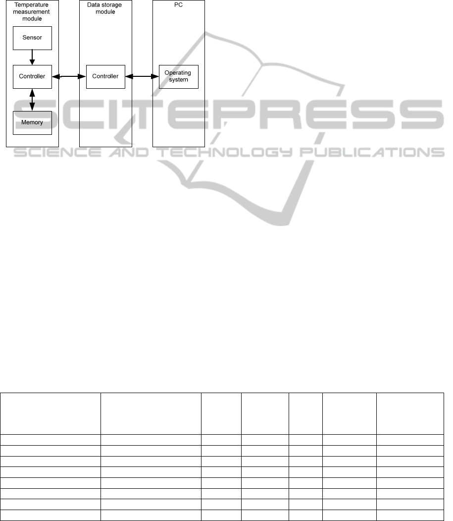
Figure 1: General system scheme.
The solution includes a thin electronic tag with
autonomous power, and a tag reading device as well
as special software for a personal computer (PC)
(Fig. 1).
2.1 Choice of the Required Electronic
Components
2.1.1 Microcontrollers
Consider the basic specifications (see Table 1) of
controllers that can be used for a proposed system.
The chip is selected according to these specifications
and the presence of temperature sensor in
microcontroller.
According to Table 1 microcontrollers
STM32F100C4T6B and MSP430F2101IPW28 for
data collection module and temperature monitoring
module respectively. The main parameters
influencing the choice were amount of memory,
processor speed and power consumption.
2.1.2 Non-volatile Memory
EEPROM (Electrically Erasable Programmable
Read-Only Memory) 24aa128
(24AA128/24LC128/24FC128, 2004) is a tag non-
volatile memory for temperature data storage.
EEPROM 24aa128 allows the following temperature
ranges: industrial: -40°C to +85°C; automotive: -
40°C to +125°C. In comparison with Flash
EEPROM 24aa128 has longest storage time, lower
power consumption in sleeping mode and while
recording, more rewriting cycles.
2.2 Tag
The tag should be slim enough to be inserted into a
product’s box or a container before sealing. The
BBT tag monitors the environmental conditions with
particular sensors (for example, temperature sensor,
humidity sensor, pressure sensor, accelerometers,
some combination of these, etc.) and logs all
detected violations of the monitored conditions with
timestamps into its non-volatile memory.
Alternatively, all data regarding environmental
conditions during the transportation and delivery can
be monitored. For example, if the item should not be
at more than some critical temperature, but had
remained the entire time at just below the critical
temperature, this also might be of interest.
The system operates in the following way (by the
example of temperature registration). The
monitoring tag records temperature inside the
monitored volumes in the range of minus 20°C to
Table 1: Basic specifications of microcontrollers (LPC1111FHN33, 2014; STM32F100x4, 2012; ATtiny13A, 2012;
ATmega48/V, 2011; MSP430F2101IPW, 2004; PIC16F676, 2014; PIC12F509, 2009; PIC10F200, 2013).
Microcontroller Core
Price
(RUB)
Flash-
memory
(kb)
RAM
(kb)
Processor
speed
(MIPS)
Energy
consumption in
optimal mode
(mА)
LPC1111FHN33 ARM 32-bit Cortex M0 100 8 2 40 8
STM32F100C4T6B ARM 32-bit Cortex-M3 78 16 4 30 8
AtTiny13A Atmel 8bit 70 1 0.064 20 11
atmega48 Atmel 8bit 80 4 0.5 20 11
MSP430F2101IPW28 TI 16bit MSP430 70 8 0.5 16 3
PIC16F676 PIC16 8bit 60 2 0.22 5 0.4
PIC12F509 PIC12 8bit 60 2 0.041 5 0.4
PIC10F200T PIC10 8bit 40 0.25 0.016 1 0.2
ICINCO2014-11thInternationalConferenceonInformaticsinControl,AutomationandRobotics
240
50°C with pre-mechanical (LED) alarm temperature
points 0°C, 2°C, 8°C, 10°C, 15°C, 25°C, and
documentation of the entry in the non-volatile
memory. Quantitative values of temperature
registered in the calendar view and in real time form
in temperature-time schedules are sent to a personal
computer using a special USB-device. The software
should allow recounting total affecting temperature
into heat calories.
The tag provides the following operation modes:
sleep mode – thermo-sensor is not active,
there is no registration and the tag is ready to
receive commands to turn on;
operating mode – thermo-sensor is active, the
tag powered by the starting device is working
in the recording mode. Registered data are
stored in non-volatile memory in encrypted
state and until reading the information is
stored in an inaccessible area of the memory;
LEDs triggering on 0°C, 2°C without counting
temperature calories.
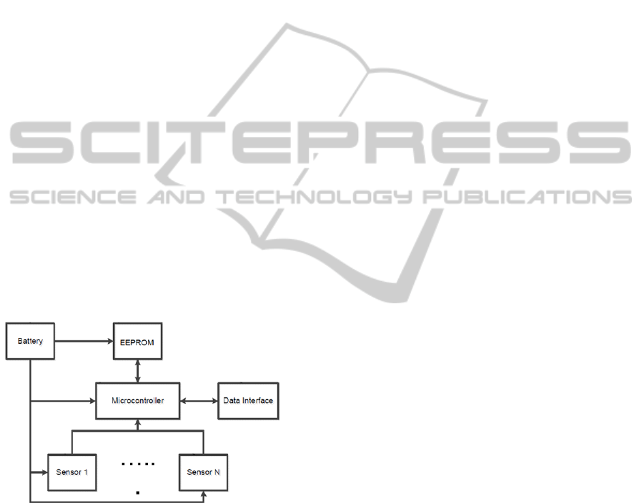
The tag includes the following components
shown in Figure 2.
A battery is a “tablet” battery of any radius (or
custom manufactured to an arbitrary shape). The
type of battery is chosen by the expected drain of the
device and its lifetime. If a wireless channel is used,
and the tag is expected to function about 2-3 years, a
lithium element battery is applied.
Figure 2: A schematic diagram of the tag.
If only a wired interface is used and the tag
lifetime is about half a year, a less expensive NiCd
battery can be implemented. Alternatively, a super-
capacitor also can be applied. Typical battery
parameters are 1.6-3.3 V, 50 mA maximum output
current, 150 mAh. The battery parameters can be
sacrificed, for example, if a smaller tag is needed
(and other reduced parameters are acceptable, such
as fewer measurements per unit time).
Non-volatile memory is used to store a tag log of
the monitored conditions (temperature, humidity,
etc). The log typically contains:
tag serial number;
tag-related data (i.e., a tag activation time, tag
manufacturing date, etc.).
The log data entries can be, for example:
TIMESTAMP1 – SENSOR1 MEASURE1 –
SENSOR2 MEASURE1 … – SENSOR N
MEASURE1
TIMESTAMP2 – SENSOR1 MEASURE2 –
SENSOR2 MEASURE2 … – SENSOR N
MEASURE2
A microcontroller (MCU) is used to:
acquire data from the sensors;
store the data into non-volatile memory;
acquire data from non-volatile memory;
send data via data interface.
The non-volatile memory can be embedded into
the microcontroller.
Sensors can be an integrated circuit or other kind
of device, with digital or analog output that converts
any physical parameter (temperature, humidity,
pressure, etc.) into voltage (analog) or code (digital).
This can be a thermocouple (a temperature sensor
based on the Seebeck effect (Encyclopedia of
Physics, 1998)), a humidity sensor (capacitive,
resistive or any other type), a pH sensor of any kind
(based on potentiometer, ion-sensitive field-effect
transistor, or on any other principle), an
accelerometer and a gyroscope (such micro-
electromechanical systems, capacitive
accelerometers, etc.), etc.
The sensors measure the value with the required
accuracy and should stay alive under any possible
conditions during the transportation. The sensors can
be embedded into the microcontroller.
A data interface is a communication channel
between the tag and the devices around it. The data
interface can be either wired or wireless.
A wireless data interface allows for
communicating with the tag during the entire period
of delivery, sending commands, reprogramming the
tag, reading data, etc. It is very helpful for different
logistic operations. The whole shipment might be
thrown away, if the tag data shows that the required
environmental conditions had been seriously
violated.
The main disadvantage is that it consumes a lot
of battery power and it significantly increases the
cost of the device. A wired interface, on the other
hand, does not allow communicating with the tag
when it is “in the box.” It can only be activated,
placed with the goods, and checked to see what was
going on with the shipment when it is unpacked. The
advantage is that it is less expensive.
ProposalofElectronicTagforMonitoringEnvironmentalConditionsDuringProductTransportation
241
Both interfaces could be implemented inside the
processor (there are processors with the wireless
communication features) or by using an external
interface controller. The wireless interface can use
either an open or proprietary protocol. The wired
interface can be custom made, I2C, SPI, SD,
iButton, etc.
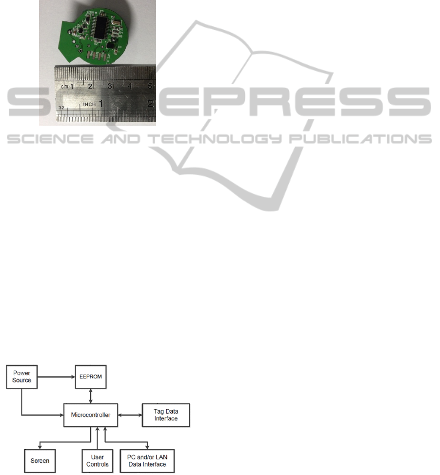
Consider the temperature monitoring module
(Figure 3).
Figure 3: Temperature monitoring module.
The system is likely to be the least expensive one
(less than 1$ per unit in 1000-pieces shipment), the
lowest active drain (hundreds of mA in active
mode), the lowest frequency (in most cases, 32 kHz
as the main clock is sufficient), the lowest pin-count
(if an external non-volatile memory is not used and
the communication interface is wired, it can even be
an 8-pin integrated circuit).
2.3 Tag Reading Device
The tag reading device can communicate with the
tag via a wired or wireless interface to transmit the
data about conditions violations and display this
information on its screen or forward it further to a
PC or to a local area network (LAN).
The reader includes the following components
shown in Figure 4.
Figure 4: A schematic diagram of the reader.
A power source is a standard battery form-factor
(AA, AAA, one or more), can be a re-chargeable
battery, can be an accumulator cell (replaceable or
not). The power source can be a super-capacitor.
The battery can be charged via AC/DC (alternating
current/direct current) adapter, DC/DC adapter, USB
connection or wirelessly, by vibration or through by
heat (thermocouple).
The non-volatile memory is used to store data
from tags, so its capacity is at least:
N * TagRAMCapacity,
where N is the number of tags the reader obtains
data from.
The non-volatile memory can have its file
system, based on commonly used (FAT, NTFS,
etc.), or based on proprietary standards.
The microcontroller acquires data from tags via a
tag data interface and stores it in the non-volatile
memory. The microcontroller monitors user controls
and performs certain actions (read tags, calibrate
time, etc.). The microcontroller obtains data from
the memory and sends the data via PC/LAN
interface.
The tag data interface is an interface compatible
with the tag's data interface. A screen is used to
output information to the user. The screen can be
very small (1 or 2 inches diagonal) to minimize the
reader's overall size or the screen can be rather large
(about 10 inches in diagonal) to maximize usability.
The screen can be combined with a touch panel
based on any technology (resistive, capacitive,
infrared, SAW, etc.) that plays a part of user
controls. The screen can also have some display
connection (HDMI, DVI, VGA, DisplayPort, etc.) to
the external display.
User controls are any buttons, touch screen
menus or triggers. The buttons can have pre-defined
functions (i.e., read tag, clear non-volatile memory,
set tag’s clock, etc.), or the buttons can be used to
navigate through the device's menu (Up, Down,
Forward, Back).
PC and/or LAN interface is used to translate data
from non-volatile memory to computer or computer
network. The interface can be wired or wireless. For
example, USB, Ethernet, Wi-Fi, Bluetooth, etc. can
be used. In addition, the memory can be embedded
into the microcontroller.
Consider the reading device (Figure 5).
ICINCO2014-11thInternationalConferenceonInformaticsinControl,AutomationandRobotics
242
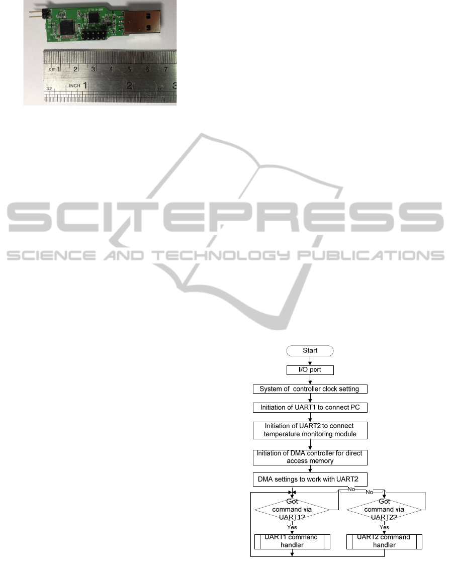
Figure 5: Reading device.
2.4 Monitoring Methods
If the tag measures data periodically, the tag only
needs to store the activation time. If the tag logs only
the times of violation of the allowed conditions, the
timestamps are used.
The amount of non-volatile memory is
determined by a predicted number of measurements
taken during the tag’s lifetime and the size of the
measurements. For example, if a temperature is
monitored (about 12 bits per measurement is
needed) and the measurement is taken once a
minute, then a one-year-long log will take up about
780 Kbytes of memory.
If only violations (for example if temperature is
higher than 10
0
C or lower than – 5
0
C) are stored,
then the additional 6 bytes of timestamps for each
measure are used resulting in a total of 60 bits per
measure. However, the conditions are expected to be
within normal range during most of the
transportation time. Thus, much less data is actually
stored in the memory.
A rough guideline is that if conditions are logged
every minute or so, then about 1 Mb per one sensor
installed on the tag per one year of its lifetime is
needed. Another concept of logging environmental
conditions that significantly reduces the amount of
used memory is not to log the measure every minute,
but to store the “overall violation” data instead.
For example, a parameter should stay at or below
A1, but it was violated and the value was A2 at one
of the measures and then, returned to normal on the
next measure. The measure is periodic and the time
between two measures is D. Therefore, in the worst
case, the duration of violation was about 2*D. The
overall violation can be estimated as:
(A2 – A1) * 2 * D
– the violation value multiplied by the duration
of the violation. Such estimate can be used to decide
if the product can still be used, but it will not store
the information of when a particular violation had
occurred.
The two of the above methods can be combined.
For example, the tag can know every time that it is
passed from one company in the delivery chain to
another via a wireless interface, so it can log data as
follows:
OVERALL VIOLATION ON DELIVERY
STAGE 1 (an ID can be used to determine which
company had delivered the goods at specific stage,
this ID can be transferred when the next
transportation stage begins)
OVERALL VIOLATION ON DELIVERY
STAGE 2
…
OVERALL VIOLATION ON DELIVERY
STAGE N.
This technique can significantly reduce the
amount of memory used compared with every-
minute-logging, but still lets the final recipient of the
cargo or the insurance company know the specific
stage of delivery when the conditions were violated.
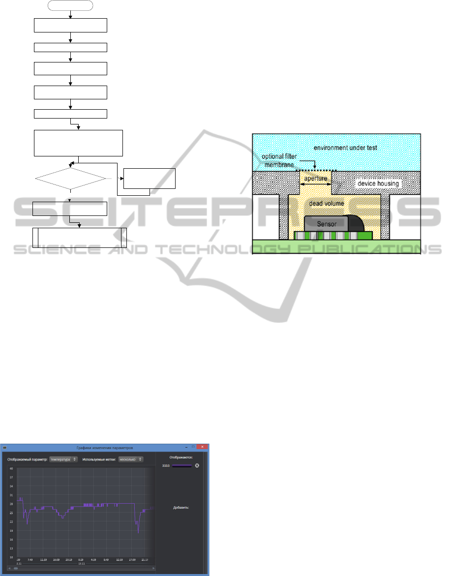
2.5 Software
As a part of the proposed temperature monitoring
system the special software has been developed. The
algorithm of data acquisition module`s software
performance is shown in Figure 6 and the algorithm
of temperature monitoring module`s software is
presented in Figure 7.
Figure 6: Algorithm of main cycle of data collecting
module`s software.
ProposalofElectronicTagforMonitoringEnvironmentalConditionsDuringProductTransportation
243
Start
System of controller
clock setting
I2C bus initiation
Analog-to-digital
converter initiation
Data acquisition
interface initiation
Timer initiation
Reading of current state of the
temperature monitoring
module from EEPROM
Module
is initiated and
active?
Transition to a
low power mode
No
Controller clock setting
from RTC
Yes
Processing of commands
from data collecting module
Figure 7: Algorithm of temperature monitoring module`s.
2.6 Testing
2.6.1 Sensors
The performance of the system with one temperature
sensor was tested using a logic analyzer LeCroy
Logic Studio 16 (LogicStudio™ 16 Channel Logic
Analyzer, 2010). The tag was subjected to changing
temperatures, obtaining the data. After they were
read by the reader and transmitted to the PC, the data
was analyzed by the software.
Obtained by the temperature monitoring module
data can be analyzed in graphical interface of PC
software as it is shown in Figure 8.
Figure 8: Temperature curve.
The testing of the tag accuracy was carried out
using a sealed chamber with zero thermal gradient.
The pre-calibrated tag was placed inside the
chamber in which the temperature was changed
every five minutes. The tag accuracy is ± 0.5
0
C.
The linearity of the sensors allow after assembly
to make a temperature measurement and store in the
tag`s memory the difference between the measured
temperature and the temperature obtained from the
reference sensor.
To increase the sensor accuracy it is proposed to
make the tag`s body in a way, shown in Figure 9.
Figure 9: Proposed tag`s body (SHT21, 2011).
The testing of the humidity monitoring is now
underway that is why the testing results are not
presented in this paper.
2.6.2 Battery
For battery testing the battery with capacity I = 225
mA/h was taken. The aim was to check its life-time
depending on the reference frequency (frequency of
requests to tag). The results are shown in Table 2.
Battery consumption diagram is shown in Figure 10.
2.7 Additional Options
As an option, an integration value of the violation
condition over time can be stored.
In general, the tag can be used multiple times. A
mechanism for charging tag’s battery, erasing tag’s
non-volatile memory and calibrating tag’s clock is
provided. Memory damp can be performed as a
command received via the data interface. Battery
replacement can be performed if the tag’s body has
an appropriate battery slot.
Battery recharging can be performed, if the tag
has a charging socket on it and a battery controller
integrated circuit on the tag (this function can also
be performed by the processor). The tag can also be
recharged wirelessly using the alternating magnetic
fields. Thus, the tag can be hermetically sealed.
ICINCO2014-11thInternationalConferenceonInformaticsinControl,AutomationandRobotics
244
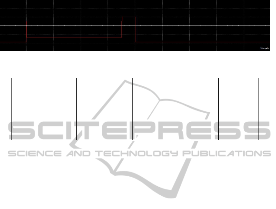
Figure 10: Battery power consumption diagram.
Table 2: Battery testing parameters and life-time.
T
(reference frequency) I (mА/h) Operation time (s)
Operation
time (h)
Operation time
(days)
0.001 34.4500000000000 23512.34 6.53 0.27
0.01 3.5350000000000 229137.20 63.65 2.65
0.1 0.4435000000000 1826381.06 507.33 21.14
1 0.1343500000000 6029028.66 1674.73 69.78
10 0.1034350000000 7831004.98 2175.28 90.64
100 0.1003435000000 8072271.75 2242.30 93.43
1000 0.1000343500000 8097218.61 2249.23 93.72
The tag’s body is manufactured from plastic or
polymer. The microcircuit that records the
temperature changes is contacting the tag`s body by
means of dielectric layer placed between the
microcircuit and tag`s body providing maximum
accuracy of temperature changes.
Tag’s clock calibration is performed via the tag’s
data interface. If required the data in the tag can be
encrypted by either symmetric or asymmetric
encryption scheme.
In order to increase battery life (particularly in
case of the wireless connection), the tag can be
programmed to turn on (and start recording and
listening for wireless commands) after a certain
period of time, as opposed to immediately after
being manufactured. Alternatively, the tag can turn
on when it detects a specific event (e.g., using a
magnetic switch/sensor).
The tag itself can be a system, distributed in
space. For example, sensors can be located in
different parts of the cargo container and the
electronic components can be located in one place,
connected (wired or wirelessly) to the sensors,
decreasing the overall cost of the system.
Electronic components with memory can be
located in a container lock, thus giving an
opportunity to log not only the environmental
conditions, but also the physical access to the
container. Low-power wireless solutions such as
Bluetooth 4.0 can significantly increase the usability
of the system. The tag data records can be accessed
not only from a specialized reader, but also from a
smart-phone, a tablet PCs, etc. This simplifies the
cargo check procedures and eliminates the need of
using specialized reader – all functionality of the
reader can be implemented in a smart-phone/tablet
PC application.
Tags can have one sticky surface covered by a
non-sticky film to prevent it from being covered
with dirt or dust, so the tag can be easily attached to
any surface. The tags (housing) can be made of a
semi-flexible printed circuit board (PCB) to be fixed
on non-flat surfaces. The tag itself can be made
flexible, e.g., using flexible mounting surfaces, such
as mylar, as housing, to make it suitable for
complex-shaped shipping and mail envelopes.
After the cargo is delivered to the warehouse, the
tags can be used in sorting and accounting processes
using additional shipment data stored in the tag’s
memory. Inserting a beeper inside the tag can help in
finding the items inside the non-automated
warehouses.
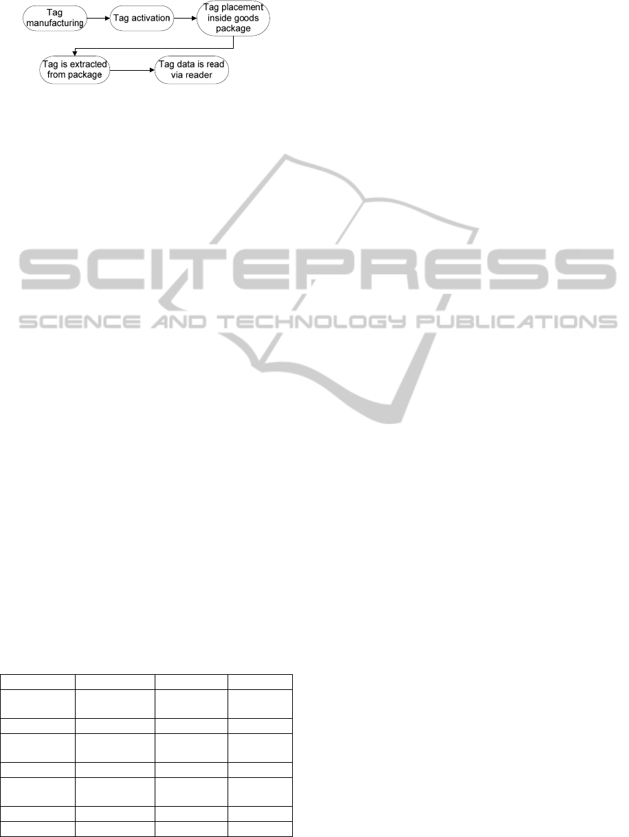
Figure 11 illustrates a tag life time flow chart.
The tag is manufactured, activated and placed inside
package (goods). The tag can be activated wirelessly
(using tag wireless interface) after it has been placed
inside the package. During transporting of the
package the tag data can be read via the tag wireless
interface. After transportation the tag is extracted
from the package and the tag data is read by the tag
reader. If needed, the data can be compressed for
storage and/or transmittal.
The tag can be implemented as a PCB module
that can be mounted (using soldering or sockets)
with other PCBs. Also, tag readers can be
implemented as stationary modules on checkpoints
ProposalofElectronicTagforMonitoringEnvironmentalConditionsDuringProductTransportation
245
of logistics to perform control automatically.
Figure 11: A life cycle of the tag.
Furthermore, the tags can have two power
sources – a direct current power source, such as a
battery, and one or more inductive coils to be
powered wirelessly, which is useful for reading data
from tags with exhausted batteries.
The tags can be synchronized with other
machines, such as robots or warehouse machinery,
via a wired or a wireless interface or through the
reader, via wired or wireless interface, to perform
goods rejection automatically. Also, the tags and/or
readers can use wired or wireless interfaces to
upload data to the Internet and to a remote server to
perform online state checks.
3 CONCLUSIONS
The tag monitors the environmental conditions with
particular sensors and logs all detected violations of
the monitored conditions with timestamps into its
memory. The tag reading device can communicate
with the tag via a wired or wireless interface to
transmit the data about conditions violations and
display this information on its screen or forward it
for storage.
As competing systems for monitoring
environmental parameters during transportation
HygroBouton (Proges-Plus company, 2014) and
Hygrochron (TERMOCHRON Elin – Russia (Elin,
2014)). Table 3 presents main specifications of the
above monitoring systems.
Table 3: Comparison of systems for monitoring
environmental conditions during transportation.
HygroBouton Hygrochron BBT
Temperature
range
-20/+85°C -20º/+85ºC -40/+86ºC
accuracy ± 0.5°C ± 1°С ± 0.5°C
Humidity
range
0-100 % 0-100 % 0-100 %
accuracy ± 5% ±1% ± 0.5%
Vibration
monitoring
- - Not limited
accuracy - - 2mg
Reader Needed Needed Not needed
The study is underway to improve the accuracy of
registered temperature and developing conditions for
providing monitoring of humidity, “lab on a chip”
chemical analysis and vibration. Moreover, humidity
monitoring accuracy and performance is being
tested.
In order to reduce the energy consumption and
increase the life-time of the tag the study will also
focus on development of the software for data
compression as well as its processing before
transmitting the data array to the PC.
REFERENCES
Kazakova O., 2010. Storage temperature of medicinal
agents. Extract. Moscow pharmacy №8 (197).
Register of medicines of Russia radar RLS+, 2004.
Doctor. Yearbook 2004 \ 7. LLC-2004 RLS. 960 pages
– 1 electron. wholesale. Disc (CD-ROM).
Temperature recorder DS1921L-F51, DS1921L-F52,
DS1921H-F5, DS1921Z-Fб, 2014. Rainbow
Electronics, official web-site. URL:
http://www.rtcs.ru/news_detail.asp?id=106.
Disposable temperature indicators WarmMark, 2013.
Intex, official web-site. URL: http://warmmark.ru.
Temperature recorders (loggers) (-40 ... +85) °C,
Comparative table of specifications, 2012. Engineer
technologies, official web-site. URL: http://
gigrotermon.ru/?find_cat=12.
Wang Jiahan, Qin Jianwang, 2011. Design and
development of intelligent terminal of special cargo
monitoring system. International Conference on
Transportation, Mechanical, and Electrical
Engineering (TMEE). Pages: 485 – 488.
Chen-Ming, Chin-Chung Nien, Jia-Liang Liao, Yu-Chee
Tseng, 2012. Development of wireless sensor module
and network for temperature monitoring in cold chain
logistics. IEEE International Conference on Wireless
Information Technology and Systems (ICWITS).
Meng Xian-yao, Meng Song, Han Xin-jie, 2009.
Optimization on Handling and Temperature Control
System of Product/Chemicals Carrier. International
Conference on Measuring Technology and
Mechatronics Automation. ICMTMA '09. (Volume:
2). Pages: 865 – 868.
Wang Keliang, Zhao Li, Liang Shoucheng, Sun Lijing,
2010. The parameters optimization of Lowered
Temperature and Gathering-Transportation technology
in Putaohua Oilfield. Asia-Pacific Power and Energy
Engineering Conference (APPEEC). Pages: 1 – 3.
Chenxia Yun, Shouyuan Chen, He Wang, Chini, M.,
Zenghu Chang, 2009. Temperature feedback control
for long-term carrier-envelope phase locking.
Conference on Lasers & Electro Optics & The Pacific
Rim Conference on Lasers and Electro-Optics.
CLEO/PACIFIC RIM '09. Pages: 1 – 2.
ICINCO2014-11thInternationalConferenceonInformaticsinControl,AutomationandRobotics
246

Saturation Properties for Hydrogen – Pressure Increments.
National Institute of Standards and Technology. NIST
Standard Reference Data. URL: http://webbook.
nist.gov/cgi/fluid.cgi?Action=Load&ID=C1333740&
Type=SatT&Digits=5&PLow=.5&PHigh=1.5&PInc=.
1&RefState=DEF&TUnit=K&PUnit=atm&DUnit=kg/
m3&HUnit=kJ/mol&WUnit=m/s&VisUnit=uPa*s&S
TUnit=N/m.
LPC1111FHN33, 2014. NXP Semiconductors, official
web-site. URL: http://www.ru.nxp.com/products/
microcontrollers/cortex_m0_m0/lpc1100/LPC1111FH
N33.html.
STM32F100x4, STM32F100x6, STM32F100x8,
STM32F100xB, 2012. STMicroelectronics. URL:
http://www.st.com/web/en/resource/technical/docume
nt/datasheet/CD00251732.pdf.
ATtiny13A, 2012. Atmel Corporation. URL: http://
www.atmel.com/ru/ru/Images/doc8126.pdf.
ATmega48/V, ATmega88/V, ATmega168/V, 2011. Atmel
Corporation. URL: http://www.atmel.com/images/
doc2545.pdf.
MSP430F2101IPW, 2004. Texas Instruments
Incorporated. URL: http://pdf.datasheetcatalog.net/
datasheets2/56/564429_1.pdf.
PIC16F676, 2014. Basic specifications. Microchip,
official web-site. URL: http://www.microchip.ru/d-
sheets/40039.htm:PIC16F676:1x1.
PIC12F509, 2009. Data Sheet. Microchip Technology Inc.
URL: http://ww1.microchip.com/downloads/en/
DeviceDoc/41236E.pdf.
PIC10F200, 2013. Data Sheet. Microchip Technology Inc.
URL: http://ww1.microchip.com/downloads/en/
DeviceDoc/40001239E.pdf.
PJSRV05W-4LC, 2011. Data Sheet. PANJIT
semiconductor. URL: http://archive.espec.ws/files/
PJSRV05W-4LC.pdf.
24AA128/24LC128/24FC128, 2004. Microchip
Technology Inc. URL: http://www.microchip.ru/
cdrom/ww1.microchip.com/downloads/en/DeviceDoc/
21191M.pdf.
Encyclopedia of Physics, 1998. – Moscow: Great Russian
Encyclopedia. – Volume 2, Volume 5.
SHT21 sensor, 2011. EasyElectronics.ru. URL:
http://we.easyelectronics.ru/part/datchik-temperatury-
i-vlazhnosti-sht21.html.
LogicStudio™ 16 Channel Logic Analyzer, 2010. Data
Sheet. LeCroy Corporation. URL: http://www.prist.ru/
produces/pdf/LeCroy_LogicStudio_Datasheet.pdf.
Hygro Bouton – Température Humidité, 2014.
Téléchargez la documentation. PROGESPLUS. URL:
http://proges.com/ftp/plugandtrack/Products_Data_Sh
ets/Fr/Thermo%20Bouton.pdf.
Elin, 2014. Thermochron iButton. URL: http://
www.elin.ru/Thermochron.
ProposalofElectronicTagforMonitoringEnvironmentalConditionsDuringProductTransportation
247
