
Design Pattern Support for Model-Driven Development
Timo Vepsäläinen and Seppo Kuikka
Department of Automation Science and Engineering, Tampere University of Technology, Tampere, Finland
Keywords: Design Pattern, Model-Driven Development, Tool Support.
Abstract: Design patterns document solutions to recurring design and development challenges. UML, as the de-facto
modeling language in software development, aims to support defining and using patterns in models.
However, as is demonstrated in the paper, the support is not sufficient for all kinds of patterns and all
meaningful ways to use patterns. In this paper, the use of design patterns is suggested for documentation
purposes in Model-Driven Development. The pattern support of UML is complemented with an approach
that does not constrain the structures that can be used in patterns. The approach, which is tool supported in a
model-driven development environment for control applications, also enables specification of part of the
information content of patterns that UML leaves intact. The developed tool support includes instantiating
and highlighting patterns in models and gathering of traceability information on use of patterns.
1 INTRODUCTION
Design patterns document proven solutions to
challenges that keep arising in design and
development work. Patterns capture expert solutions
for reuse purposes for both expert developers and
less experienced ones. In UML modeling, support
for using patterns is only partially enabled by the
language. The support for the use of patterns is
based on Collaboration and CollaborationUse
concepts (OMG, 2011) that have been developed
along the entire language specification from
parameterized collaborations (Sunyé et al., 2000).
However, in addition to the standard approach,
many tool vendors, e.g. No Magic (No Magic,
2014), have implemented additional pattern support
in a more ad hoc manner. Such support for patterns
is in many tools based on informal UML templates
that can be copied into design models to create
instances of the patterns. In addition, copying the
templates may utilize wizards that enable modifying
pattern occurrences to specialized forms, by e.g.
selecting existing elements to pattern-specific roles.
However, without referencing pattern definitions
the information about the occurrences is endangered
to vanish. With application specific names of e.g.
properties, classes and interfaces, the occurrences
are difficult to notice later for both developers and
the tools. To avoid losing this information, patterns
should be modeled and their occurrences marked in
the models.
With its concepts, UML aims to support the
definition of patterns in library models and their
instances in models. It appears that the collaboration
concepts of UML have been designed with
traditional GoF (Gang of Four) (Gamma et al., 1994)
patterns in mind: with focus on co-operating objects
as properties of classes. However, as will be
demonstrated, the UML concepts may not be
sufficient for all kinds of patterns and foreseeable,
meaningful ways to use patterns. Nevertheless, when
patterns are utilized in software projects,
documenting their use in models could be of great
value. Especially this is the case with development
processes that emphasize the use of models, e.g.
Model-Driven Development (MDD).
In addition to solutions, design patterns include
textual information about, for example, their
contexts and the problems being solved. In
(Alexander, 1979), the pattern concept is defined as
a three-part rule expressing a relation between a
context, a problem and a solution. A design pattern
defined with the UML concepts, however, is likely
to provide only information about the solution part
of the pattern leaving the other important aspects
unspecified.
This paper addresses the aforementioned issues.
A pattern modeling approach is presented, which is
less restrictive than that of UML and enables
277
Vepsäläinen T. and Kuikka S..
Design Pattern Support for Model-Driven Development.
DOI: 10.5220/0004990002770286
In Proceedings of the 9th International Conference on Software Engineering and Applications (ICSOFT-EA-2014), pages 277-286
ISBN: 978-989-758-036-9
Copyright
c
2014 SCITEPRESS (Science and Technology Publications, Lda.)

specification of part of the information content that
UML does not address. The approach is tool
supported in UML AP (UML Automation Profile)
tool environment (Vepsäläinen et al., 2008) for
MDD of control applications. The contributions of
this paper are as follows. A set of concepts for
defining and using design patterns is presented and
rationalized. The benefits of the concepts are pointed
out and compared to pattern support in UML. The
use of patterns and pattern markings is proposed to
benefit development work, documentation and
learning of developers within MDD.
The rest of this paper is organized as follows.
Section 2 reviews work related to modeling and
facilitating the use of design patterns in UML
context. Section 3 outlines and discusses how the
use of patterns could benefit specifically MDD. The
means of UML to define and use patterns are
presented in section 4, in addition to pointing out
shortcomings in the support with use of well-known
example patterns. Section 5 presents a new approach
to model patterns and pattern instances and
illustrates the tool support developed based on the
concepts. Before conclusions, section 6 discusses the
work presented and future work to be done.
2 RELATED WORK
The roots of design patterns, as a concept, lie in
building architecture and work of Alexander, see
(Alexander et al., 1977) and (Alexander, 1979). In
software development, the use of patterns began to
gain popularity after publication of the Gang of Four
(GoF) patterns (Gamma et al., 1994), in which the
application area was object oriented programming
and software, but not so much modeling. However,
support for patterns was also developed to UML.
In addition to area of expertise, e.g. building and
software engineering, design patterns vary in their
abstractness and levels of details specified. For
example, (Lasater, 2010) describes patterns as
design tools to improve existing code whereas
(Buschmann, 1999) focuses on architectural
patterns that can have varying implementations.
Patterns for safety systems development can be
found e.g. in (Rauhamäki et al., 2013), the patterns
mainly describing roles of elements.
The need for automated tool support to define
and use design patterns in models has been
identified by several researchers. Support has also
been developed for specifying patterns, identifying
pattern instances, detecting parts in models where
patterns could be used as well as for instantiating
and visualizing patterns.
(France et al., 2004) presents a formal pattern
specification technique that is based on UML. It is
intended for specifying design patterns and checking
conformance of pattern instances to their
specifications. In (France et al., 2003), automatic
transformations are developed for refactoring
patterns into models. The approach is based on
specifications of pattern-specific problems, solutions
and problem-to-solution transformations.
Detection of points in models where design
patterns could be used has been studied, among
others, in (Briand et al., 2006). In the paper,
detection rules are specified with OCL (Object
Constraint Language) and combined with decision
trees. Detecting design pattern instances has been
studied in (Tsantalis et al., 2006) the approach being
based on representing both the models and patterns
with graphs and applying graph similarity scoring.
Automating application and evolution of design
patterns has been proposed and studied in (Dong and
Yang, 2006), (Xue-Bin et al., 2007) and (Kajsa and
Majtás, 2010). In (Dong and Yang, 2006), QVT
(Query/View/Transformation) transformations are
developed for evolving pattern applications to new
ones, e.g. adding new observers to an Observer
pattern instance. (Xue-Bin et al., 2007) uses XSLT
(Extensible Stylesheet Language Transformations)
for pattern-specific transformations to add patterns.
The work in (Kajsa and Majtás, 2010) utilizes model
transformations that are guided with UML
stereotypes to mark the points to which the patterns
should be added.
Visualizing design patterns in model diagrams
has been addressed in (Dong, 2002) and (Jing et al.,
2007). (Dong, 2002) presents several notations to
highlight and distinguish patterns and pattern-related
elements in diagrams. Among them is the
collaboration notation that is also used in this paper.
In (Jing et al., 2007), a UML profile is developed for
specification of pattern roles that elements in pattern
occurrences play. Based on the profile, the authors
have developed a web service tool that integrates to
e.g. Rational Rose to visualize patterns.
3 DESIGN PATTERNS TO
FACILITATE MDD
Design patterns provide many general, well-known
benefits to development work. For example, they
encapsulate knowledge and experience, provide
ICSOFT-EA2014-9thInternationalConferenceonSoftwareEngineeringandApplications
278

common vocabulary for developers and enhance
documentation of designs (Agerbo and Cornils,
1998).
More recently, design patterns have been seen to
mark points in which developers have been
potentially faced with challenges. Design patterns
can be considered as predefined, reusable design
decisions. However, they may require configurations
for specific applications (Jansen and Bosch, 2005).
Patterns are proven and general whereas design
decisions are more tentative, specific to an
application and also possible to be choices between
solutions (Harrison et al., 2007), e.g. patterns. By
marking a design pattern instance, a developer thus
not only instantiates and configures a solution but
marks a challenge and documents a decision.
The use of patterns in models can thus extend the
documentation value of the models with
architectural knowledge. However, especially
patterns could be valuable in MDD in which the
purpose is to shift development efforts from
documents to models. To demonstrate this point, we
discuss their use to a few selected purposes.
Patterns can be used to gather statistics. When
patterns are marked in models that are used
throughout the development process, it is possible to
gather statistics on the use of the patterns. Pattern
markings promote traceability between the solutions
(of the patterns) and their use in software products.
It is possible to study and compare work and
preferred solutions of developers. Companies and
teams can set up rules for using patterns in order to
unify designs. For example, it could be agreed that a
specific kind of challenge is always solved with a
standard way in applications of a specific domain.
Also metrics could be defined to evaluate
software products in an application domain or work
of different developers. Extensibility and
modifiability, for example, are quality attributes that
many classic design patterns aim to improve. As a
consequence, it is possible that similar software
products could be compared in terms of preferred
quality attributes by comparing the patterns and
amount of patterns used in the products.
Design patterns can promote learning of new
developers, too. When best practices and expert
solutions are documented as patterns and pattern
instances marked in design models, the models can
be used as training material. New developers can
look for pattern instances, in which kinds of contexts
they have been used and how they have been used
by experienced developers. Optimally, design
pattern instances could be highlighted in models and
diagrams in order to ensure their discovery.
Diagrams with pattern annotations could also be
used as parts of written documents when copied to
such documents, when necessary.
It can be argued that the mentioned benefits are
not restricted to the use of patterns in MDD only.
However, the benefits from increasing the
documentation value of models are of special
importance in MDD. This is because one of the
objectives of MDD is to gain benefits by changing
the focus of development efforts from documents to
models. If the aim is not to produce written
documents in which challenges, decisions and
solutions could be included, the only places where
they can be added are the models.
On the other hand, in development practices
other than MDD there may not always be need to
model all parts of the developed systems. If all parts
and aspects are not modeled, being able to produce
e.g. statistics from models may not result in
unbiased information on use of patterns. It is
possible that the results from systematic use of
patterns in models could be more usable in MDD
context than with traditional development processes.
4 SUPPORT FOR DESIGN
PATTERNS IN UML
In UML, patterns are defined with the Collaboration
concept that extends both the StructuredClassifier
and BehavioredClassifier concepts, similarly to the
Class concept of the language. A pattern is a set of
cooperating participants that are owned by a
Collaboration instance as its properties, similarly to
properties of a class. For each pattern-specific role
there should be a property owned by the
Collaboration. Required relationships between the
participants are specified with connectors between
the properties. The features required from the
participants are defined by the classifiers (e.g.
classes or interfaces) that are used as types of the
properties.
Pattern instances are represented with the
CollaborationUse concept. A CollaborationUse
represents an application of a Collaboration (pattern)
to a specific situation. CollaborationUses are owned
by classes to contents of which the Collaborations
(patterns) are applied. Contents (properties) of the
applying classes are bound to roles (properties) of
the Collaborations with Dependencies that are called
role bindings. The entities (properties) playing the
roles in the pattern instances must be owned by the
classifiers owning the CollaborationUse elements.
DesignPatternSupportforModel-DrivenDevelopment
279

Graphically, Collaborations and
CollaborationUses can be defined in composite
structure diagrams (CSDs). In case of defining a
Collaboration (pattern) the root element of the
diagram is the Collaboration, whereas in case of a
CollaborationUse the class owning it. In other
diagrams, CollaborationUses can be visible in
compartments related to the applying classes, if
supported by the tool being used.
4.1 Challenges with the UML Pattern
Modeling Approach
The approach of UML for defining and using design
patterns is formal and well-defined. However, when
compared to, for example, literature presentations of
many well-known patterns, the UML concepts
cannot be used in a literature prescribed way. A
CollaborationUse cannot be used e.g. in a class
diagram describing classes of a package because in
that case the participants would be classes (instead
of properties) and owned by a package (instead of a
class). For example a set of classes as in Figure 1
could not be marked as an Observer (Gamma et al.
1994) pattern instance.
Figure 1: A class diagram illustrating the Observer pattern.
A rationale for claiming that the familiar
structure in the figure cannot be an Observer
instance could be that a class diagram does not yet
indicate definite occurrence and use of instances of
the classes in the pattern-specific way. Instead, the
UML approach would be to define another class,
create instances of the classes (of the figure) as
properties of the other class and connect them to use
the services of each other. Graphically this could be
done with CSDs.
CSDs were not available at the time e.g.
Observer pattern was authored, which is a possible
explanation for the tool support to differ from the
literature (or vice versa). However, from a pragmatic
point of view, it may not be worthwhile to require
definition of the class instances in CSDs because
CSDs are not used as commonly (e.g. in industry) as
class diagrams are. On the other hand, if a developer
deliberately designs classes so that they can be used
according to a pattern, it should be possible for her
to mark the decision, e.g. for documentation
purposes.
Another example related to the lack of pattern
modeling capabilities in UML is related to
architectural patterns. A well-known example of
such a pattern is the Layers pattern (Buschmann,
1999). An intuitive means to illustrate the use of
Layers in a UML model could be to present the
packages and classes that an application is built of in
a layered-like orientation as in Figure 2. One could
also use component diagrams and arrange the
components to a layered like orientation, like in
(Buschmann, 1999) pp.35. However, neither of these
approaches could be marked as a Layers instance.
Packages, that class and component diagrams are
used to describe, are not classes and thus cannot own
CollaborationUses. And if they could, the packages
and components would not be properties of a class.
Figure 2: A layered architecture pattern illustration in a
class diagram.
Observer and Layered Architecture patterns were
used as examples above because of their familiarity.
However, they are not the only patterns that may be
difficult to apply in UML models. When patterns
and pattern instances are defined and applied as
contents of classifiers, use of patterns to describe
aspects other than those related to classes and
properties becomes difficult. Especially this can be
seen to restrict the support for architectural patterns.
Related to pattern languages, UML does not
define means to specify relations between patterns.
According to the language specification (OMG,
2011), Collaborations can extend others. However,
there is no means to specify, for example, that after
applying a pattern it could be advisable to apply
another, related pattern.
Lastly, the means of UML for defining
information content of patterns other than solutions,
e.g. context and problem, are limited. The
Collaboration concept does not include textual or
other kinds of properties for such purposes.
ICSOFT-EA2014-9thInternationalConferenceonSoftwareEngineeringandApplications
280
5 A NEW PATTERN MODELING
APPROACH
Generally, the concepts that can be used in models
conforming to a modeling language are defined in
the metamodel of the language. The concepts
available in UML models, for example, are defined
in the UML metamodel (OMG, 2011) which in turn
has been defined with use of Meta Object Facility
(MOF). The metamodel of the new pattern modeling
concepts, with relations to existing UML concepts,
is presented in the next sub-section.
5.1 Metamodel for Defining, Marking
and using Design Patterns
What pieces of information a pattern is obviously
required to include are a name (identifier), problem
(that the pattern solves), context (in which the
pattern can be applied) and the solution, as also
suggested in (Alexander, 1979). On the other hand,
as argued in the previous section, the modeling
approach should not restrict the nature of solutions
in patterns. Practical patterns may consist of
practically any modeling elements, e.g. components
or class definitions. It should also be possible for
other modeling elements than classes to contain
elements that are parts of a pattern instance.
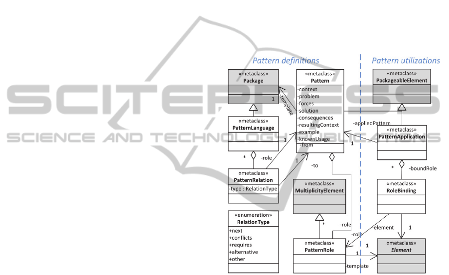
The basic concepts of the new pattern modeling
approach are depicted in Figure 3 that has been
divided into two parts. The concepts on the left-hand
side are aimed for defining patterns whereas the
concepts on the right-hand side for using and
marking patterns instances. Although they are part
of the same metamodel, it is assumed that design
patterns could be defined in specific library models
(preferably by experienced developers) and their
instances used in application models (of the systems
being modeled). Similar division of concepts exists
already in UML related to profiles and stereotypes.
Stereotypes are defined by experts in profiles and
then used in a number of application models.
Although stereotypes can be considered as tools for
design work and altering the semantics of modeling
elements, they are defined in UML models similarly
to the concepts that they specialize.
The Pattern and PatternApplication concepts are
aimed for defining patterns and pattern instances,
respectively. Their UML counterparts are the
Collaboration and CollaborationUse concepts.
However, instead of defining (only) contents of a
classifier, Patterns contain textual information which
has been structured based on the canonical form of
patterns (Appleton, 1997) with addition of
Consequences from the Alexandrian form
(Alexander et al., 1977).
The Pattern concept is extended from the UML
PackageableElement concept so that Patterns can be
defined within package hierarchies. The main
contents of Patterns are PatternRoles that are used to
specify structural and behavioral roles specific to the
Patterns. Multiplicities define the limitations to
numbers of modeling elements playing the roles in
pattern instances. PatternRoles can also refer to
template elements that are specific to the roles. Their
purpose is to enable development of tool support to
facilitate the creation of pattern instances.
Figure 3: The metamodel of the new pattern modeling
concepts; UML concepts are highlighted with grey color.
RoleBindings are owned by PatternApplications
and they bind pattern instance specific elements to
the roles of the patterns. The metaclasses of bound
elements are not restricted since (concrete) elements
of UML all extend the abstract Element concept that
is used as the type of the meta-reference. The same
applies to SysML and UML AP modeling elements
in the supporting tool; they can be used in patterns
and pattern instances as well.
PatternLanguage concept is a lightweight
approach to pattern languages, allowing patterns to
be organized into hierarchies. With PatternRelations,
patterns can be organized into (pattern) sequences
describing meaningful orders of using patterns, and
sequences combined to simple languages. Relations
also allow the specification of alternatives, patterns
requiring other patterns and patterns that conflict
DesignPatternSupportforModel-DrivenDevelopment
281

with each other. This aspect is yet to be defined in
more detail.
The major differences of the approach in
comparison to plain UML are as follows. The roles
of patterns have been separated from their template
elements in the template packages. Pattern
definitions may contain textual information. The
model elements playing the roles in patterns and
their instances are not restricted to be instances of
any specific UML (or e.g. SysML) metaclass.
Lastly, PatternApplications are owned by packages
that are used in models in any case.
The concepts relieve the restrictions of UML so
that, for example, the patterns presented in section
4.1 could be marked as instances of suitable pattern
definitions. Since elements playing roles in a pattern
need not be properties, for example class definitions
of Figure 1 - or some other variation of the pattern –
could be marked as an Observer pattern instance. A
structure like that could also be marked as a pattern
instance regardless of whether the constructs would
be defined in the same or different package. It would
only affect to which package should own the
PatternApplication element. Constructing patterns
from classes, packages and components is also
possible, which would enable marking the structure
of Figure 2 as an instance of the Layers pattern.
As a downside, the approach is less formal than
that of UML. Because of the freedom to define
patterns to consist of any elements, it is more
difficult to confirm correctness of pattern
applications, for example. Since the approach does
not restrict the elements that play roles in a pattern
instance to be owned by a single model element, it is
also possible for pattern instances to disperse to
several places in models due to, for example, model
refactoring. That is, although simple checks of
consistency can be automated with e.g. the
multiplicity restrictions more responsibility over
correctness of pattern definitions and instances is left
for developers in the approach.
Another restriction of the approach is related to
the portability of it to other tools, which is caused by
the metamodel additions that the approach requires.
This aspect is discussed in more detail in section 6.
5.2 Illustrative Example
To demonstrate the use of the concepts, they are
used in an example to define Observer pattern and to
apply it to a model. The starting point in the example
is a situation in which a PressureControl class would
need to be made capable of receiving notifications of
new (pressure) measurements from a
PressureMeasurement class. A class diagram
illustrating this starting point is shown in Figure 4.
Figure 4: An example diagram before applying a pattern.
In order to apply Observer (Gamma et al., 1994),
it needs to be first defined with the presented
modeling concepts. A tree view of a model defining
the pattern with the concepts is shown in Figure 5.
The pattern is in the example defined in a Package
that contains the Pattern element (Observer) as well
as a template Package. The pattern includes roles
related to it (Observer, Subject and
ConcreteObserver). The classes and interfaces of the
template package were illustrated in Figure 1; they
also define several operations that are hidden from
the figure below. Textual information related to the
pattern, e.g. context and problem, is stored in the
properties of the Pattern element.
Figure 5: A tree view of Observer definition with the
modeling concepts.
The example class diagram, after applying the
pattern, is illustrated in figure 6. The diagram also
illustrates how the pattern instance is visualized with
the collaboration notation. The modifications from
applying the pattern include addition of an interface
(Observer), an interface realization as well as several
operations specific to the role elements in the
pattern, e.g. update(). These elements have been
added based on the template elements illustrated in
Figure 1.
Another view to the results is presented in figure
7 that illustrates the references between the model
trees related to the pattern definition and pattern
instance. The operations and other added model
elements are contained in the model in a similar
manner than any model elements. The information
about the pattern instance, on the other hand, is
ICSOFT-EA2014-9thInternationalConferenceonSoftwareEngineeringandApplications
282

stored in a PatternApplication element. The
PatternApplication contains the RoleBindings that
link the pattern instance specific elements to the
general roles of the pattern definition.
Figure 6: A visualization of an Observer pattern instance.
Figure 7: References from a pattern instance to definition.
5.3 Tool Support for using Patterns
With the tool support, the purpose has been to
facilitate the use of patterns and to demonstrate the
benefits from their use. The metamodel extensions
to UML AP and UML modeling concepts, see
Figure 3, were defined with Eclipse Modeling
Framework (EMF) that is a Meta Object Facility
(MOF) implementation used by the UML AP tool
(Vepsäläinen et al., 2008). In addition to
implementing the concepts, tool support has been
developed to instantiate and to visualize patterns in
models as well as to generate documentation from
models. Of these functions, first two have been
implemented with the core of the tool whereas the
latter extends the documentation generation work in
(Vepsäläinen and Kuikka, 2011).
5.3.1 Instantiating Patterns
Compared to instantiating patterns from templates in
an ad hoc manner, the use of the presented concepts
requires additional work. Defining patterns with the
Pattern and PatternRole elements has to be done
only once for each pattern. PatternApplications,
however, need to be created and configured for each
new instance. As such, it is natural that this task
should be facilitated with tool support. In the tool,
this task has been integrated to a wizard. Compared
to existing pattern wizards in UML tools, the novelty
of the wizard is in managing the new concepts.
The process of instantiating patterns is performed
as follows. The user of the tool initiates the wizard
from a tool menu. As a response, the tool scans
through available pattern libraries in order to find
available patterns. New libraries can be added to the
tool by registering them with an (Eclipse) extension
point developed for this purpose.
The user of the tool is provided with a list of
available patterns. When selecting a pattern to apply,
part of the textual information (problem, context and
solution) related to the patterns is visible to the user,
as illustrated in Figure 8. After selecting a pattern,
the pattern (definition) that should be referenced by
the PatternApplication to be created is known. In
case of the design diagram root element being a
package, the PatternApplication to be created can be
owned by the package. Otherwise, it can be created
to be owned by the package closest to the diagram
root in the model hierarchy. The wizard proceeds to
processing (iterating through) the pattern roles.
For each role, the wizard enables the user to
select an existing element from the active diagram to
act in the role. If the pattern in question defines a
template, it is also possible to copy an element for
the role from the template. For PatternRoles that the
user has either selected an element for or copied it
from the template, the wizard creates RoleBindings
that bind the elements to the roles of the pattern. In
case of using existing elements in roles of a pattern,
their contents (elements owned by them) are
compared and completed to correspond to those of
the templates by copying missing contents.
Technically the wizard has been implemented so
that it only collects the information from the user
whereas actual model changes are performed at once
after completing the wizard. The purpose of this is to
enable possibility to collect model modifications to a
single (undoable) command. However, currently
undoing a pattern application requires manual work.
It is also possible to modify pattern instances
after creating them. PatternApplications and
RoleBindings can be selected from the outline view
and modified with the properties view of the tool.
Elements related to a pattern instance can also be re-
organized and it is possible to apply more instances
of compatible patterns. Information on which
elements are part of a pattern instance is stored in a
PatternApplication specific to the instance and the
RoleBindings of it. They are not affected by
additions of new elements or simple changes to the
bound elements, e.g. re-naming or moving them.
DesignPatternSupportforModel-DrivenDevelopment
283
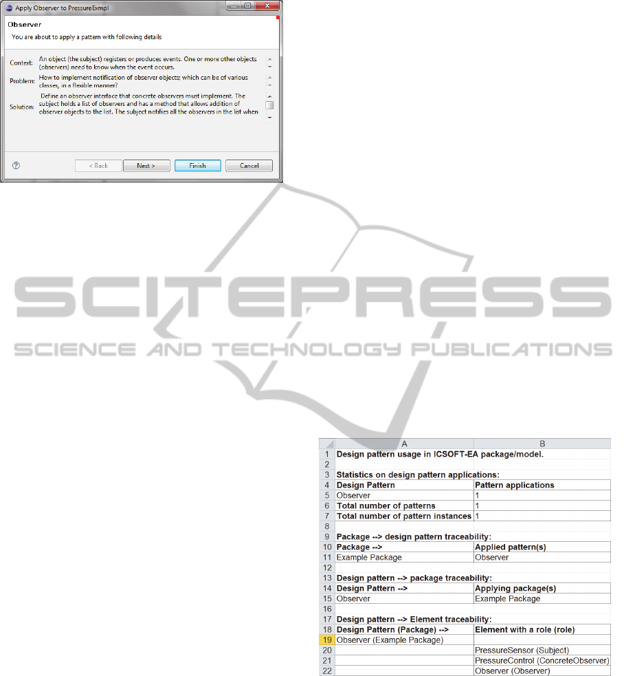
Figure 8: The pattern information page of the wizard.
5.3.2 Visualizing Patterns
Although pattern instances are always visible in the
outline view of the tool, they are not visible in
diagrams by default. This is rational since the
amount of details in a diagram should be relatively
small to keep it understandable. Patterns can also be
considered as explanatory information that may not
be required all the time. However, when pattern
applications are necessary to be shown, e.g. for
documentation or teaching purposes, it should be
possible to visualize them in diagrams.
Visualization of a pattern is initialized from a
menu of the outline view of the tool while at the
same time selecting the PatternApplication to be
shown. As a response, a dotted ellipse shape with
lines to the model elements playing the roles in the
pattern instance is created. The ellipse represents a
PatternApplication (pattern instance) and contains
the name of the pattern (definition). Connections to
the role elements show the names of the
corresponding pattern roles.
The graphical presentation of pattern instances is
similar to CollaborationUses in CSDs, with addition
of <<PatternApplication>> to distinguish between
them. An example graphical presentation of an
Observer pattern application was presented in Figure
6. In the figure the pattern has been applied to a
client application model so that the names of the
concrete classes are different from the names of the
template classes, which were shown in Figure 1.
5.3.3 Patterns as a Part of Documentation
One of the main motivations of this work has been
to use patterns for documentation purposes in MDD.
Since design patterns and design pattern instances
are modeled with dedicated elements, it is possible
to track the design patterns that are used in a model
of an application as well as the number of instances
of the patterns. Since PatternApplications are owned
by packages, it is possible to trace the parts of
models in which a design pattern is used. Starting
from packages, it is again possible to track the
patterns that are used in the packages.
Exporting documentation is initiated by the user
of the tool that selects the root of the model from the
outline view, selects export functionality and then
traceability information. First sheets of the generated
(Microsoft Excel) spreadsheet are described in
(Vepsäläinen and Kuikka, 2011) whereas last two
are dedicated to design patterns.
The first of the new sheets lists the design
patterns that are used in a model. The sheet is
collected by searching all PatternApplication
instances in the model. The number of instances for
each design pattern (definition) as well as the total
amount of patterns are calculated and shown. With
traceability matrices, the sheet presents package to
design pattern traceability (the patterns that are used
in each package), design pattern to package
traceability (in which packages each design pattern
is used) and lastly design pattern to element
traceability. In the latter matrix, each design pattern
instance is traced to all elements that play roles in
the instance. An example sheet presenting
traceability for the pressure sensor example of
Figure 6 is presented in Figure 9.
Figure 9: An exemplary automatically generated
traceability sheet.
The second of the new sheets focuses on design
patterns themselves. At the beginning of the sheet a
list of patterns, instances of which can be found
from the model, is repeated with the amount of
pattern instances. After this table, the sheet presents
printouts of information for each design pattern used
in the model including context, problem, forces,
solution (textually), consequences, resulting context,
example, and known usage.
ICSOFT-EA2014-9thInternationalConferenceonSoftwareEngineeringandApplications
284

6 DISCUSSION AND FUTURE
WORK
This paper has discussed the use of design patterns
in UML based modeling and their potential benefits
in model-driven development. Shortcomings in
UML design pattern support have been pointed out
and an additional set of modeling concepts has been
presented.
The need for a new approach to utilize patterns
in models originates from the UML pattern
modeling concepts that restrict patterns to describe
contents of classifiers. The information content of
actual published patterns, however, is not restricted
to such a narrow scope. Patterns may not always
concern concrete programming language level
aspects and their information content is not restricted
to solutions only. For example, solutions of patterns
may consist of packages, components or even use
cases. In addition, patterns include information
about their contexts and problems for which the
patterns provide the solutions.
The presented, simple set of modeling concepts
enhances the UML limitations by enabling patterns
to include textual information and to consist of
practically any elements that a pattern author finds
useful. As a downside, the approach leaves more
responsibility over the correctness of patterns and
pattern applications to developers. The portability of
the approach to other tools is also questionable,
which is caused by metamodel modifications.
The approach introduces new metaclasses to the
MOF based UML metamodel so that implementing
the approach in other tools would require similar
additions. The other extension mechanism of UML,
light weight profiles that consist of stereotypes,
however, would not have enabled all the required
additions. According to the UML specification
(OMG, 2011), stereotypes cannot be used to insert
new metaclasses or metareferences between existing
metaclasses, for example. With stereotypes (without
new metaclasses), it would have been possible to
include the textual information in the Collaboration
concepts of UML. However, CollaborationUses
would still be owned by classes and their other
specified constraints would still apply.
In future work, it is our intention to focus on
safety related patterns, examples of which can be
found e.g. in (Rauhamäki et al., 2013). Safety related
systems constitute an application domain in which
documentation is of special importance. This is
because of the need to justify the safety of the
developed applications against safety standards. For
software safety functions, the standards focus on
development methods, practices and solutions that
are recommended for different levels of safety. On
the other hand, safety standards require traceability
between requirements, design, implementations and
test cases, among others. This is the problem domain
that we foresee to be possible to facilitate with safety
pattern modeling and extending the presented
documentation generation work.
7 CONCLUSIONS
Design patterns document solutions and capture
expert knowledge to recurring challenges in design
and development work. The scope of design patterns
that can be found from literature varies in terms of
area of expertise and abstraction level. Many
patterns present rather conceptual solutions than
solutions that could be copied or modeled always in
the same way. However, although the UML
concepts have been enriched along the development
of the entire language, the pattern support is still
restricted to collaborating properties of classes.
In this work, the issue has been addressed by
defining and implementing a set of pattern modeling
concepts that can be used to complement the UML
concepts. The approach is not restricted to modeling
of classifiers only but enables patterns to consist of
practically any modeling elements that an author of
a pattern finds useful.
Tool support for automating the use of the new
concepts has been developed for instantiating
patterns, visualizing patterns in diagrams as well as
collecting documentation and statistics from models.
The tool and concepts have been used by researchers
working in the project. They have been found useful
and will be used to gather more use experience in
software engineering courses at the department of
Automation Science and Engineering at Tampere
University of Technology.
The tool supported functionalities are also related
to the way in which design patterns could be used to
facilitate model-driven development. Patterns enable
including additional documentation to models.
Patterns enrich models with information on
challenges, points of decisions as well as traceability
between solutions and their use in specific
applications. Visualizing patterns in diagrams may
both support learning of developers and increase the
value of diagrams in written documents. Knowledge
on pattern use can be gathered to statistics to
compare applications and work of developers.
Patterns and rules for using them can also be used to
unify work of developers in teams and companies.
DesignPatternSupportforModel-DrivenDevelopment
285

REFERENCES
Agerbo, E., Cornils, A. 1998, How to preserve the benefits
of design patterns, ACM SIGPLAN Notices, ACM,
pp. 134-143.
Alexander, C. 1979, The timeless way of building.
Alexander, C., Ishikawa, S., Silverstein, M. 1977, Pattern
languages, Center for Environmental Structure, vol. 2.
Appleton, B. 1997, Patterns and software: Essential
concepts and terminology, Object Magazine Online,
vol. 3, no. 5, pp. 20-25.
Briand, L.C., Labiche, Y., Sauve, A. 2006, Guiding the
application of design patterns based on uml models,
Software Maintenance, 2006. ICSM'06. 22nd IEEE
International Conference on, IEEE.
Buschmann, F. 1999, Pattern oriented software
architecture: a system of patters, Ashish Raut.
Dong, J. 2002, UML extensions for design pattern
compositions, Journal of object technology, vol. 1, no.
5, pp. 151-163.
Dong, J., Yang, S. 2006, QVT based model transformation
for design pattern evolutions, in: Proceedings of the
10th IASTED international conference on Internet and
multimedia systems and applications.
France, R.B., Kim, D., Ghosh, S., Song, E. 2004, A UML-
based pattern specification technique, Software
Engineering, IEEE Transactions on, vol. 30, no. 3, pp.
193-206.
France, R., Chosh, S., Song, E., Kim, D. 2003, A
metamodeling approach to pattern-based model
refactoring, Software, IEEE, vol. 20, no. 5, pp. 52-58.
Gamma, E., Helm, R., Johnson, R.,Vlissides, J. 1994,
Design Patterns: Elements of Reusable Object-
Oriented Software. Pearson Education.
Harrison, N.B., Avgeriou, P., Zdlin, U. 2007, Using
patterns to capture architectural decisions, Software,
IEEE, vol. 24, no. 4, pp. 38-45.
Jansen, A., Bosch, J. 2005, Software architecture as a set
of architectural design decisions, Software
Architecture, 2005. WICSA 2005. 5th Working
IEEE/IFIP Conference onIEEE, pp. 109.
Jing, D., Sheng, Y., Kang, Z. 2007, Visualizing design
patterns in their applications and compositions,
Software Engineering, IEEE Transactions on, vol. 33,
no. 7, pp. 433-453.
Kajsa, P., Majtás, L. 2010, Design patterns instantiation
based on semantics and model transformations, in
SOFSEM 2010: Theory and Practice of Computer
Science, Springer, pp. 540-551.
Lasater, C.G. 2010, Design patterns, Jones & Bartlett
Publishers.
No Magic, Inc. 2014, MagicDraw. Available:
http://www.nomagic.com/products/magicdraw.html
[2014, 1/23].
OMG, 2011. Unified Modeling Language Specification
2.4.1: SuperStructure, Object Management Group.
Rauhamäki, J., Vepsäläinen, T., Kuikka, S. 2013, Patterns
for safety and control system cooperation, Proceedings
of VikingPLoP 2013 Conference.
Sunyé, G., Le Guennec, A., Jézéquel, J. 2000, Design
patterns application in UML, in ECOOP 2000—
Object-Oriented Programming Springer, pp. 44-62.
Tsantalis, N., Chatzigeorgiou, A., Stephanides, G.,
Halkidis, S.T. 2006, Design pattern detection using
similarity scoring, Software Engineering, IEEE
Transactions on, vol. 32, no. 11, pp. 896-909.
Vepsäläinen, T., Hästbacka, D., Kuikka, S. 2008, Tool
Support for the UML Automation Profile - For
Domain-Specific Software Development in
Manufacturing, Software Engineering Advances,
2008. ICSEA '08. The Third International Conference
on.
Vepsäläinen, T., Kuikka, S. 2011, Towards model-based
development of safety-related control applications,
Emerging Technologies & Factory Automation
(ETFA), 2011 IEEE 16th Conference on.
Xue-Bin, W., Quan-Yuan, W., Huai-Min, W., Dian-Xi, S.
2007, Research and implementation of design pattern-
oriented model transformation, Computing in the
Global Information Technology, 2007. ICCGI 2007.
International Multi-Conference on, IEEE.
ICSOFT-EA2014-9thInternationalConferenceonSoftwareEngineeringandApplications
286
