
Optimization of Gas Turbine Compressor Blade Parameters for
Gas-dynamic Efficiency under Strength Constraints
Leonid Shabliy and Aleksandr Cherniaev
Samara State Aerospace University, Moskovskoe r., Samara, Russia
JSC "CADFEM-CIS", Avrora st., Samara, Russia
Keywords: Multiobjective Optimization, Compressor Blade, Fluid-Structure Interaction, Genetic Algorithm.
Abstract: This article describes an approach for optimization of gas turbine compressor blade based on one-way fluid-
structure interaction (FSI) analysis coupled with evolutionary optimization algorithm. Commercial CFD and
FE code ANSYS was used for the simulations. Paper gives detailed description of developed geometric
model, CFD and FE models, as well as description of employed optimization technique. Obtained results
indicate that adiabatic efficiency and pressure rate of compressor can be increased up to 23% and 7%
correspondingly by rational selection of relative positions of compressor blade cross-sections.
1 PROBLEM
Gas turbine power plants (gas turbines) are
increasingly used as power sources in a variety of
military and civilian applications. This includes
propulsion for air, land, overwater and even
underwater applications, as well as electric power
plants, pumping stations, etc. Gas turbine power
plants, in comparison with the piston engines, have
greater body-weight capacity, more favorable
traction performance and longer service life. They
do not need any cooling system and thus have no
problems associated with it. In addition, they are
unpretentious in operation, being easy to run at
lower temperatures, not requiring fine air
purification and having high environmental
performance, as well as relatively low emissions and
low consumption of oil.
Major disadvantage of gas turbine engines is
complexity of their design. This results in the high
cost of their life cycle (Kuzmenko et al., 2007). In
turn, complexity of design results from the mutual
influence of different physical processes
simultaneously occurring in gas turbine. Reduction
of life-cycle costs of a gas turbine requires its
optimization with regard to different efficiency
parameters (e.g., adiabatic efficiency and pressure
rate of compressor, weight) and taking into account
multiple constraints (e.g., strength, stiffness, natural
frequencies etc.)
A number of examples of such analyses have
been described in the literature. In (Lian and Liou,
2005) multi-objective optimization was performed to
maximize stage pressure ratio and minimize weight
of NASA rotor67 compressor blade. It was
conducted over 32 design variables controlling
geometry of 4 cross-sections along the blade span.
Optimization resulted in 1.8% and 5.4%
improvement of baseline design for pressure ratio
and weight, correspondingly. Simulations used
TRAF3D CFD code combined with response surface
generator and genetic algorithm. In (Lee and Kim,
2000) and, more recently in (Samad and Kim, 2008),
optimization was carried out for two conflicting
objectives, such as total pressure ratio and adiabatic
efficiency, using only 3 design variables controlling
geometry of stacking line of compressor blade. As in
the previous case, genetic algorithm was used in
(Samad and Kim, 2008) as optimization technique.
In (Chen et al, 2007) blade parameterization
technique was developed to reduce number of design
variables in optimization. Optimization was
performed using combination of gradient-based
algorithm with response surface approximations.
1.73% of increase in adiabatic efficiency for NASA
rotor37 was reported. Another example of
parameterization of compressor blades for multi-
objective optimization is given in (Sommer and
Bestle, 2011). The parameterization technique is
based on the use of B-splines. Presented simulations
were two-dimensional.
This short review allows determining two main
523
Shabliy L. and Cherniaev A..
Optimization of Gas Turbine Compressor Blade Parameters for Gas-dynamic Efficiency under Strength Constraints.
DOI: 10.5220/0004994905230528
In Proceedings of the 4th International Conference on Simulation and Modeling Methodologies, Technologies and Applications (SIMULTECH-2014),
pages 523-528
ISBN: 978-989-758-038-3
Copyright
c
2014 SCITEPRESS (Science and Technology Publications, Lda.)
distinctive features of existing approaches to
optimization of compressor blades. First, they
consider the problem as multi-objective. Second,
rational techniques for decreasing of a number of
design variables are continuously been sought.
In this paper we present an approach for optimal
design of compressor blades aiming to maximize
such conflicting parameters as adiabatic efficiency
and pressure rate of compressor. All simulations in
our study are full scale and three-dimensional. As
compared to results presented in the literature, our
approach is different in taking into account strength
constraints due to coupled CFD-FE simulations and
in use of formalized procedure for choosing design
variables based on parameters correlation study.
Described optimal design procedure, instead of
being based on an in-house code, utilizes
commercial widely used software ANSYS, which
makes it reproducible and ready-to-use by
engineering practitioners.
2 NUMERICAL SIMULATIONS
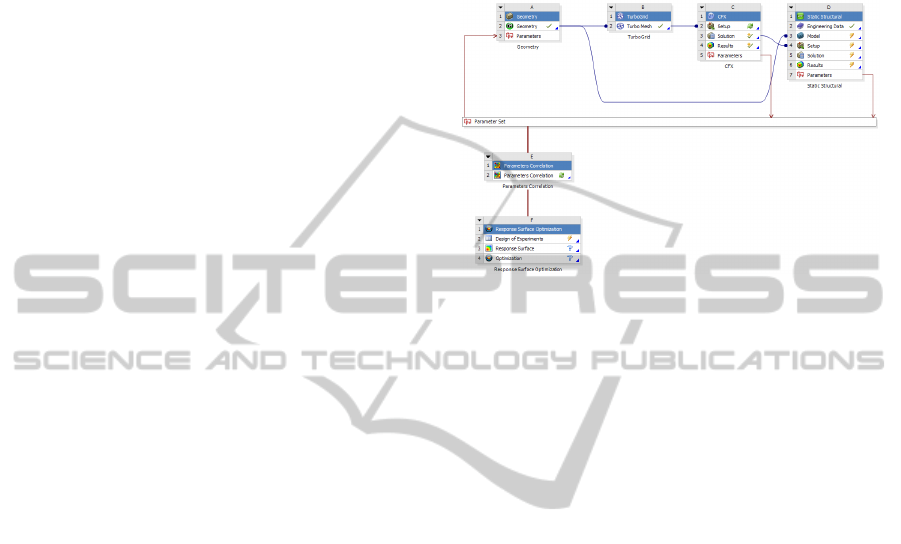
All simulations were done in the ANSYS
Workbench environment using the following set of
modeling applications (Figure 1):
ANSYS Design Modeler for geometric modeling
(DesignModeler User Guide, 2011);
ANSYS TurboGrid for high-quality hexagonal
meshing of inter-blade channel (ANSYS
TurboSystem User Guide, 2011);
ANSYS CFX for gas dynamics simulations
(ANSYS CFX-Solver Modeling Guide, 2011);
ANSYS Static Structural for strength analysis
(ANSYS Mechanical Application User's Guide,
2011);
Parameters Correlation and Response Surface
Optimization toolboxes for identification of most
influencing design variables, calculation of
response surfaces and optimization (Design
Exploration User Guide, 2011).
In general, a single simulation loop can be
described as follows. First, for a given set of design
variables created by response surface generator, a
geometric model of compressor blade is constructed.
This procedure was automated by establishing
parametric relationships between blade geometric
elements (see section 2.1). Next, this model is
discretized in Turbogrid and transferred to ANSYS
CFX to perform gas-dynamics analysis. This
analysis has two goals. First, it evaluates adiabatic
efficiency and pressure rate of the compressor, and
second, it calculates pressure field on the blade,
which is then transferred to ANSYS Static Structural
and used there as loading condition for strength
analysis. This scheme implements so called one-way
fluid-structure interaction (FSI) procedure. In Static
Structural, strength is assessed by means of von
Mises criterion.
Figure 1: ANSYS Workbench project configured for
optimization of compressor blade.
Such direct analyses are repeated few times to
construct response surfaces for design objectives
(pressure rate and adiabatic efficiency) and
constraint (maximum von Mises stress in the
model). Once this part is accomplished, genetic
algorithm implemented in ANSYS DesignXplorer is
used to solve multiobjective optimization problem.
In the next subsections, each step of this
procedure is described in more details.
2.1 Geometric Model
The parametric geometry model was built in
ANSYS Design Modeler and consisted of a blade
and a shank. Blade was built using three cross-
sections (blade profile on the hub, the middle and
peripheral diameter) by Skin/Loft operator
(Figure 2). Each profile was constructed according
to the method of circular arcs and line segments
(Figure 3) and had the following variable
parameters:
blade angles at the input (β
1
) and outlet (β
2
);
chord (b);
radius of the input (R
in
) and output (R
out
) edges.
Parameterization of the profile was carried out by
specifying geometric and dimensional constraints.
Dimensional constraints were defined by a set of
equations which establish relationships between
parameters of cross-sections (Figure 4). For
example, the angles between blade sides and its
horizontal axis (A12 and A13) can be found as inlet
SIMULTECH2014-4thInternationalConferenceonSimulationandModelingMethodologies,Technologiesand
Applications
524
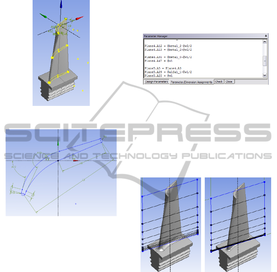
Figure 2: Blade geometry model with highlighted profiling
cross-sections.
Figure 3: Blade profile sketch with imposed dimensional
constraints.
vane angle plus/minus the half of inlet sharpening
angle w
1
:
Plane4.A12=@beta1 - @w1/2
Plane4.A13=@beta1 + @w1/2
Due to the fact that sketches of blade cross-
sections were built in separate planes, each profile
had two more degrees of freedom in the global
coordinate system, namely the flat shift in the
tangential plane. This allowed utilizing in parametric
framework well-known technique of shifting blade
cross-sections, which is typically used for
discharging a blade from the aerodynamic forces.
Therefore blade geometry, being the most
complex part of the vane, depends on a large number
of parameters. Even though we used in this work
relatively simple profiling technique, it resulted in
more than 20 independent variables. To reduce the
number of parameters in optimization, it was
decided to vary only the following ones:
inlet angles at each section (β
1_0
, β
1_1
, β
1_2
);
shift of middle and peripheral sections (ΔX
1
,
ΔX
2
);
fillet radius at the junction of the fir-tree root and
blade (R).
Figure 4: Design Modeler Parameter Manager Window.
ExportPoints tool from BladeEditor module of
ANSYS Design Modeler was used to transfer the
geometric model of inter-blade channel to
TurboGrid. FlowPath operation was used to indicate
the meridional sections (Figure 5). For adequate
representation of fillet geometry in gas-dynamic
analysis, density of sections was higher in the hub
region. Position (Span) of each section was
parameterized using algebraic expressions as a
function of the radius of the fillet R (Figure 5).
Figure 5: Parameterization of Span element using
FlowPath operation: blade with large fillet radius has
less layers (left) than blade with small fillet radius (right).
2.2 Gas-Dynamic Model
As it was mentioned before, TurboGrid was used to
create a mesh of inter-blade channel (Figure 1).
Typically, finer mesh provides higher precision of
numerical simulations. However, optimal design
problems require multiple analyses with different
sets of design variables. Thus a compromise
between simulation accuracy and computational cost
should always be sought. Based on this, in the
OptimizationofGasTurbineCompressorBladeParametersforGas-dynamicEfficiencyunderStrengthConstraints
525
present work meshing of inter-blade channel
resulted in 60 elements. This allowed maintaining
sufficient accuracy in representation of physical
phenomena of interest and solving the optimization
problem in about 60 hours.
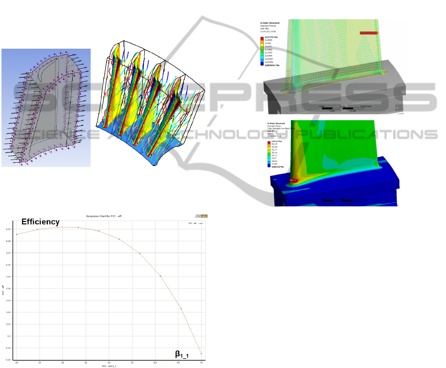
The gas-dynamic model was created in the CFX-
Pre preprocessor using Turbo-mode tool. The air
was set as working body and option of domain
motion was set to the constant speed rotation.
Boundary conditions were also given constant,
which included absolute incident velocity of the air
at the inlet and static pressure at the outlet
(Figure 6).
Figure 6: Model prepared for gas-dynamic simulation
(left) and obtained results: streamlines and pressure
contours (right).
Figure 7: Dependence of efficiency on the angle of the
blade inlet in the middle section.
For further reduction of computational expenses,
rough convergence criteria were set, including the
residual (RMS) of 0,001 and the maximum number
of iterations of 150. The accuracy of the results was
found to be enough for adequate representation of
the physical phenomenon of interest and conducting
parametric studies.
Results obtained in a trial calculation allowed
estimating the dependence of flow parameters on the
shape of the blades (Fig. 7).
2.3 Finite Element Model
Pressure field exported from CFX to Static structural
and results of FE analysis for equivalent stresses are
exemplified in Figure 8. As expected, applied
loading creates a stress concentration region at the
filleted area near junction of the fir-tree root and the
blade.
Figure 8: Blade finite element model: imposition of
aerodynamic loads (upper) and equivalent stresses (lower).
The main loads acting on the blade are the
aerodynamic and centrifugal forces. The
aerodynamic load is transmitted to the blade as the
pressure of gas flow field calculation. In such
loading conditions, stress-strain state is determined
by the following parameters:
fillet radius (R), which determines the size of the
stress concentration zone;
relative position of the central and peripheral
sections, which influence distance between
center of gravity of the blade and its center of
rotation. In turn, it influences value of the
centrifugal force.
3 OPTIMIZATION PROCEDURE
3.1 Choice of Design Variables
It is obvious that the problem under consideration, in
terms of optimization, refers to the class of NP-
SIMULTECH2014-4thInternationalConferenceonSimulationandModelingMethodologies,Technologiesand
Applications
526
complete problems. It means that dimension of
design space exponentially depends on the number
of variables. Thus, it is important to identify the
most important input parameters and exclude from
consideration those which have low influence on the
design criteria and constraints. This can help
significantly reduce complexity of the optimization
problem in terms of computational time.
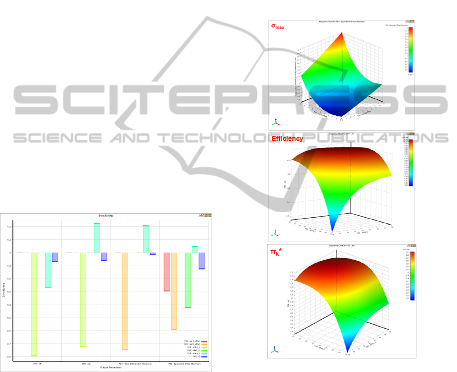
Global sensitivity analysis was carried out to
assess dependence of adiabatic efficiency, pressure
rate and maximum equivalent stress on inlet angles,
shift of middle and peripheral cross-sections and
fillet radius. For these calculations, Parameter
Correlation tool from ANSYS DesignXplorer was
used.
Results of the calculations presented in Figure 9.
They allowed drawing the following conclusions:
the value of adiabatic efficiency and pressure
ratio mainly depends on blade angles at inlet,
middle and far-sections, as well as (to a lesser
extent) fillet radius;
maximum equivalent stress is mainly affected by
the shifts of middle and peripheral cross-
sections, as well as by a fillet radius and a blade
angle at the inlet.
Based on this, it was decided to use all of the
above parameters as variables in optimization
problem.
Figure 9: Dependence of the upcoming criteria
optimization of variable parameters.
3.2 Optimization Formulation
As a result, the optimization problem can be
formulated as follows:
Maximize efficiency=f(α
1_0
,α
1_1
,α
1_2
,Δx
0
,Δx
1
,Δx
2
,R), and
Maximize π
k
*
= f (α
1_0
, α
1_1
, α
1_2
, Δx
0
, Δx
1
, Δx
2
, R)
under the constraint of σ
max
≤ [σ],
where α
1_0
, α
1_1
, α
1_2
– blade inlet angles to the cross
sections 0…2; Δx
0
, Δx
1
, Δx
2
– shift of cross
sections at tangential plane; R – fillet radius at the
junction of the blade in fir-tree root.
The first step in solving any optimization
problem using ANSYS DesignXplorer is
construction of response surfaces for design
objectives and constraints. In the current work,
response surfaces were represented using second
order polynomials. Some of them are shown in
Figure 10. “Central composite design” method was
used to select sample points.
Figure 10: The constructed response surface parameters to
be optimized (in the axes α1_1, α1_2): maximum
equivalent stress (on the top), adiabatic efficiency (in the
middle), pressure ratio (on the bottom).
The ranges of the design parameters were as
follows: ±5 mm for the displacement of middle and
peripheral sections; 30...70º for the angles; 2...5 mm
for the fillet radius. The maximum allowable
equivalent stress for the titanium blade was assumed
to be 800 MPa. Equal weighting factors were used
for both design criteria.
OptimizationofGasTurbineCompressorBladeParametersforGas-dynamicEfficiencyunderStrengthConstraints
527
In the next stage, optimization strategy was chosen.
The only method available in DesignXplorer for
multiobjective optimization is so called Genetic
Algorithm. This method implements mathematical
model of evolutionary process.
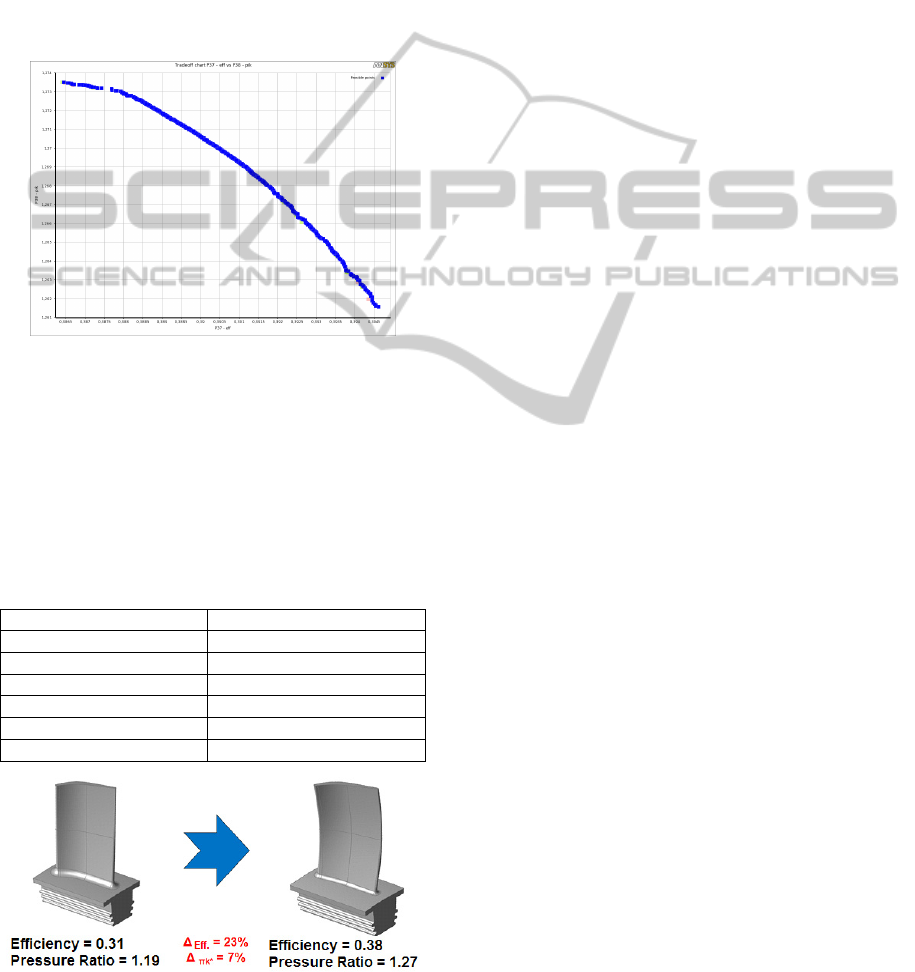
3.3 Optimization Results
When importances of design criteria are not equal,
all possible optimal solutions belong to so-called
Pareto front. Calculated Pareto front for the current
problem is shown in Figure 11.
Figure 11: Pareto front.
Results obtained for the case of equal importance
are presented in Table 1. Their comparison with the
corresponding values for baseline design is shown in
Figure 12. Increase of adiabatic efficiency and
pressure ratio obtained as a result of optimization is
equal to 23 and 7%, respectively.
Table 1: The values of the design parameters of the blade,
obtained during optimization.
Parameter Optimal value
α
10
, degrees 42.52
α
11
, degrees 32.11
α
12
, degrees 47.53
Δx
0
, mm 4.92
Δx
1
, mm -0.83
R, mm 2.75
Figure 12: Comparison of the original and the optimized
shape of the blade.
4 CONCLUSIONS
Multiobjective optimization of gas turbine
compressor blade parameters has been performed
using ANSYS software. Significant increase of gas-
dynamic efficiency in terms of adiabatic efficiency
and pressure ratio was achieved with strength
constraints remained satisfied. Obtained results
indicate that presented approach can be successfully
used for the optimal design of compressor blades.
REFERENCES
Kuzmenko M. L., Shmotin Yu. N., Egorov I. N.,
Fedechkin K. S., 2007. Optimization of the gas turbine
engine parts using methods of numerical simulation.
In Proceedings of the ASME Turbo Expo, 2007,
Vol. 6, pt. A, pp. 425-431.
Lian Y., Liou M. S., 2005. Multi-Objective Optimization
of Transonic Compressor Blade Using Evolutionary
Algorithm. Journal of Propulsion and Power, 21 (6).
Lee S-Y, Kim K-Y., 2000. Design optimization of axial
flow compressor blades with three dimensional
Navier-Stokes solver. KSME International Journal,
14(9), 2000, pp. 1005 - 1012.
Samad A., Kim K-Y., 2008. Multi-objective optimization
of an axial compressor blade. Journal of Mechanical
Science and Technology, 22, 2008, pp. 999-1007.
Chen N., Zhang H., Xu Y., Huang W., 2007. Blade
Parameterization and Aerodynamic Design
Optimization For a 3D Transonic Compressor Rotor.
Proceedings of the 8th International Symposium On
Experimental and Computational
Aerothermodynamics of Internal Flows. Lyon, July
2007. Paper reference: ISAIF8-0021.
Sommer L., Bestle D., 2011. Curvature driven two-
dimensional multi-objective optimization of
compressor blade sections. Aerospace Science and
Technology, 15(4), 2011, pp. 334 - 342.
ANSYS User's Guides (DesignModeler, TurboSystem,
CFX-Solver Modeling Guide, Design Exploration,
Mechanical Application), 2011. ANSYS, Inc.
SIMULTECH2014-4thInternationalConferenceonSimulationandModelingMethodologies,Technologiesand
Applications
528
