Location Based Alteration of Simulation Models for Multi Screen VR
Applications
Ralf Waspe and Juergen Rossmann
Institute for Man-Machine Interaction, RWTH Aachen University, Aachen, Germany
Keywords:
Location Based Deployment Model, Meta Data System, Multi Screen VR, Distributed Simulation.
Abstract:
Simulation and VR application models may depend on parameters that are location dependent. To enhance
portability and to speed up deployment times we propose a method, which uses a separate location based
deployment model that gets loaded automatically by the simulation system. Subsequently loaded simulation
models will get altered by the system, according to the deployment model. The deployment model can be
further used as a topology for distributed rendering and simulation, or as a basis for an application controlling
a multi-screen VR wall.
1 INTRODUCTION
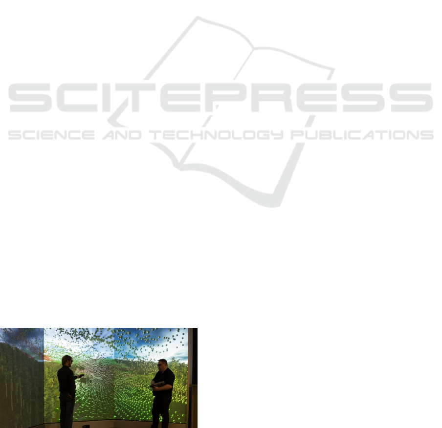
Even complex simulation and virtual reality models,
like the one shown in Figure 1, should be easily trans-
ferable from one location to another. For example a
developer may work on his or her desktop computer
and then bring the simulation to a customer with an-
other desktop machine, a mobile device or a cluster of
computers used for distributed simulation (Fujimoto,
2001) or rendering (Marino and Vercelli, 2007). Prob-
lems may arise when details of the simulation or the
user interaction depend on the physical setup or the
location of the hardware. For example the IDs of joy-
sticks needed for user interaction may differ from site
to site or the IP address of the local database that holds
part of the simulation model or data may change.
Figure 1: A 3D simulation of wind turbulences in a forest,
running on a multi-screen hardware setup.
Furthermore, if the setup consists of several com-
puters used for multi-screen rendering, the number
and arrangements of screens and associated render
clients may vary from location to location. Another
example would be the positioning and size of graphics
overlay presented on a desktop computer or a multi-
screen VR environment. While the later details are
not strictly relevant for the simulation, they are essen-
tial for the user interaction, the ease of use and there-
fore the acceptability of the VR application.
The easiest solution to this problem is to alter the
simulation model or the associated application set-
tings at each location. However, this may lead to
inconsistencies of the model and longer deployment
times. Furthermore, an update of the model becomes
more error prone and can not be handled automati-
cally by a version control system.
In this paper we therefore propose a method that
uses a model of the hardware setup and the infrastruc-
ture of the location the simulation should be deployed
at, which automatically gets loaded by the simulation
system. The deployment model is then used to au-
tomatically alter the subsequently loaded simulation
model. This way the simulation model can remain
unchanged upon transfer between different locations.
Because the deployment model is loaded by the same
simulation system it is convenient to use the same
modeling approach as used for the simulation mod-
els themselves.
The rest of the paper is organized as follows: in
Section 2 we will briefly introduce the schema-less
core database component upon which the used simu-
lation system is based. In Section 3 this core is ex-
panded by the simulation functionality itself, in order
to build a simulation model. In Section 4 we show
how the core is extended for the deployment model
103
Waspe R. and Rossmann J..
Location Based Alteration of Simulation Models for Multi Screen VR Applications.
DOI: 10.5220/0005007101030109
In Proceedings of the 4th International Conference on Simulation and Modeling Methodologies, Technologies and Applications (SIMULTECH-2014),
pages 103-109
ISBN: 978-989-758-038-3
Copyright
c
2014 SCITEPRESS (Science and Technology Publications, Lda.)
and how it is used to alter the simulation model. In
Section 5 we show how the deployment model is used
for distributed simulation and rendering and further-
more, how we use the deployment model with a sep-
arate instance of the simulation system to operate and
control the hardware and software used in a multi-
screen VR environment. Section 6 concludes the pa-
per.
2 THE CORE DATABASE
In this section only those aspects of the used simula-
tion system will be introduced briefly, which are rel-
evant for the scope of this paper. A more detailed
description of the system and its relevance to the field
of eRobtics is given in (Rossmann et al., 2013a).
2.1 Database Structure
As depicted in Figure 2 the simulation system is built
around the ”Versatile Simulation Database” (VSD), a
schema-less database kernel. In order to retain seman-
tic information the VSD is an object oriented graph
database as introduced by (Gyssens et al., 1994).
These databases haven proven their adaptability to a
wide field of applications, as shown in the overview
by (Angles and Gutierrez, 2008).
Figure 2: The core database can be extended by application
specific plugins.
The core system itself only provides an empty
database and the ability to load plugins based on a
configuration file. All simulation functionality is im-
plemented as plugins to the core system. These can
provide data schema needed for specific simulation
tasks (such as discrete event or 3D simulation) or
they can implement further capabilities, such as a
graphical user interface, user interaction or rendering.
Model loading is also handled by plugins, thus allow-
ing the system to adapt to new data sources without
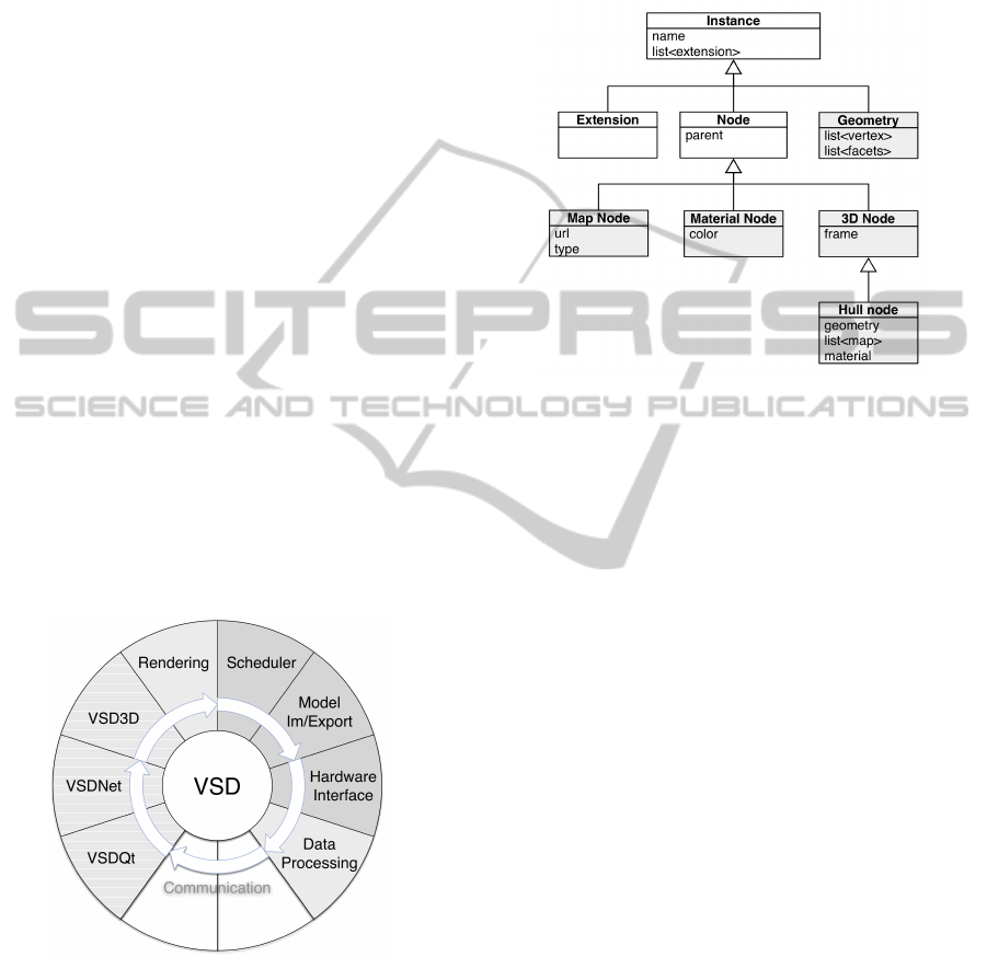
alterations to the kernel. A very simplified class hi-
erarchy of the VSD core is shown in white in Figure
3.
Figure 3: The VSD core components (white) and a data
schema extension for 3D simulation (gray).
All data describing the state of the simulation is
held within the database as properties, which in turn
are part of classes derived from the Instance base
class. Properties provide standardized getter and set-
ter methods, as well as he ability to serialize the con-
tained data. The serialization is used for loading and
saving a model, as well as for streaming the simula-
tion state in distributed and parallel simulation. Prop-
erties can hold any value or a references to other en-
tities derived from the Instance base class within the
database.
The spanning tree (Diestel, 2012) of the database
consists of nodes (or classes derived from node, both
of which are derived from Instance), with the edges
of the graph defined by parent-child relations between
nodes. Nodes can be augmented by extensions. In an
object-oriented fashion both nodes and extensions can
not only provide data storage through properties, but
also functionality to work with the contained data.
A multi-graph can be created by attaching any In-
stance to a reference property, thus defining additional
arbitrary sets of edges within the database. This can
be useful for modeling different arrangements of in-
stances for special views of the database, such as a
rendering graph, as proposed by (Tobler, 2011).
2.2 Meta Information
Another very important aspect is the availability of
introspection at run time through a meta data system.
An instance is associated with a meta instance and a
SIMULTECH2014-4thInternationalConferenceonSimulationandModelingMethodologies,Technologiesand
Applications
104
property has a corresponding meta property. A meta
instance can have meta methods, a list of functions
that are invokable on a specific instance through the
use of the meta system. Furthermore, a meta instance
can create a corresponding instance. It is thus possible
to create and interact with an entity derived from In-
stance without having to know the specific class. This
provides the ability decrease linker based plugin inter-
dependence.
It is also possible to create a new meta instance
at run time (together with meta properties and meta
methods), which can create instances that can be in-
teracted with just like hard-coded classes. This en-
ables the adaption of new schema even at run time.
This ability can be used to adapt schema from remote
databases, as describe in (Casanova et al., 2007),
3 THE SIMULATION MODEL
It is possible to extend the simulation core described
above by functionality for discrete event or 3D simu-
lation. For a possible way to integrate object-oriented
Petri-net (Bastide, 1995) based discrete event simula-
tion system see (Rossmann et al., 2013b). The sim-
plified schema extension for 3D simulation is shown
in gray in Figure 3.
3.1 Settings and Properties
There are two distinct categories of data used by a
simulation system. The first is data describing the
state of the simulation, which is held in properties.
All other data (for example window size and arrange-
ment, GUI language or navigation preferences) are
stored in settings.
It is our policy that a model must still function
properly if the corresponding settings are deleted.
Settings are held in XML files and can be refer-
enced using standard methods such as XPath (Anders,
2007). The structure of a settings file is dependent on
the application only and does not change with the cur-
rently used simulation model.
When transferring a model from a desktop to a
multi-screen setup the settings may need to be altered
as well. While it is convenient on the desktop to show
elements such as tool bars or message and navigation
windows, a VR wall should show only the rendering
window in full screen.
In contrast to settings, the positions of alterable el-
ements within the graph database change from model
to model and can not be described by a single univer-
sally applicable path. Therefore, instances with prop-
erties, which can or should be overwritten are tagged
by a dedicated class of extensions. These extensions
are used in conjunction with the deployment model,
which will be detailed later in subsection 4.1.
3.2 Event Scheduler
Not only the simulation schema, but also its time con-
troller is a plugin to the core system. The simulation
is driven by tasks that are called by an event sched-
uler, as described in (Henriksen, 1977). In the case of
3D simulation the tasks get executed periodically.
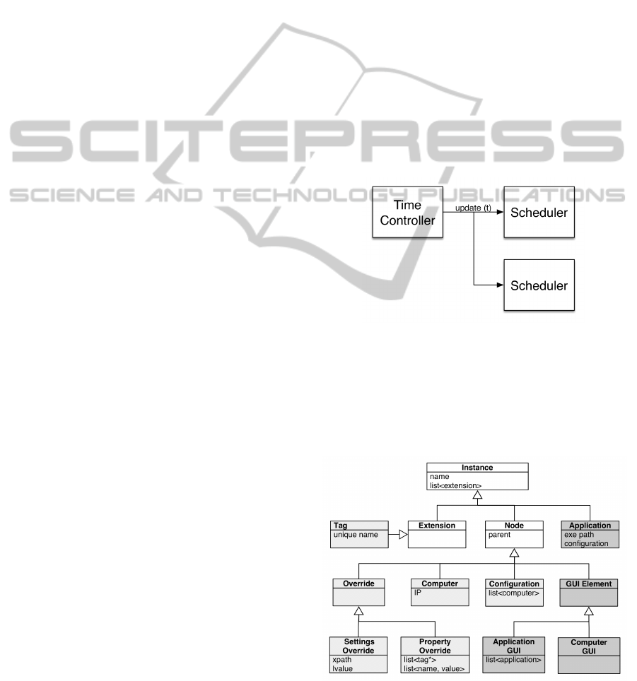
A scheduler is triggered by a time controller,
which may exists in various implementation. The
most common time controller is a predefined real time
controller, with the option to link the simulation time
to the wall time. Figure 4 shows a time controller trig-
gering several schedulers, which is useful for running
parallel simulations.
Figure 4: A time controller triggering several schedulers.
Both scheduler and tasks have one or more con-
texts, which can be either built-in or user defined. A
scheduler holds a list of tasks and will only execute
those tasks that share at least one common context.
Figure 5: An example of data schema extending the VSD
core. The VR deployment model in light gray and classes
used by the control application in dark gray.
LocationBasedAlterationofSimulationModelsforMultiScreenVRApplications
105
4 THE DEPLOYMENT MODEL
The VSD core can be extended by a deployment
schema as depicted in light gray in Figure 6. This
schema can then be used to create a model of the hard-
ware infrastructure, which can be loaded automati-
cally by the software before the simulation model.
The deployment model consists of two parts,
which will be discussed below: One describing pos-
sible model and settings alterations and another de-
scribing the hardware setup.
4.1 Settings and Property Override
The simulation systems caches all XML based set-
tings in a DOM tree. Therefore, the override of set-
tings simply comes down to replacing a string entry
at a given path. This happens before either the GUI is
created or the simulation model is loaded.
In order to replace property values in the simula-
tion model a more complex method must be applied.
• Before the simulation is started all tag extensions
are collected. If the unique name given in the tag
extension matches the name of a property override
node the extension is inserted into the tag list of
the override node. This list will not be saved and
is not accessible via the GUI.
• Each override has a list of property names and cor-
responding string values. Through the meta in-
formation system the properties belonging to the
parent of the tag extension are found and the se-
rialization feature of the property is used to apply
the string value.
When the simulation is started it will not know the
origin of instances and properties within the database.
4.2 Hardware
As mentioned in Section 2.1 the simulation system
gets started with a configuration, which contains a list
of plugins to be loaded. After loading the deploy-
ment model the software searches for a configuration
node corresponding to its current setup. This node
contains a master and slave list of references to com-
puter nodes. By identifying the computer node corre-
sponding to the system, it is then known whether the
simulation should be run in master or slave mode. In
master mode the scheduler context is not altered and
all tasks are executed. In slave mode it is set to a pre-
defined Distribution-Receiver context, thus only tasks
that also have this context are executed.
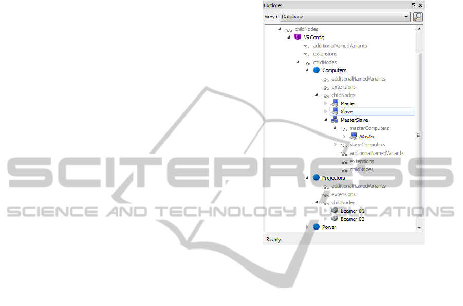
The deployment model can also contain descrip-
tions of display devices (such as projectors), power
switches or motion trackers and other input devices.
An example of a hardware configuration loaded by
the simulation system can be seen in Figure 6.
Figure 6: The loaded deployment model shown in the sim-
ulation system.
Due to the ability of the simulation database to
contain references, it is easy to assign a computer to
a display device, the display device to a power switch
and so on. Using properties a display device also con-
tains information on whether it is stereo enabled and
may have the ability to perform basic operations, such
as turning the device on and off. Specific known types
of display devices can be sub-classed and filled with
more functionality, which may be used by the control
application described in the next section.
5 FURTHER USES OF THE
DEPLOYMENT MODEL
In this section two use-cases for the deployment
model are presented.
5.1 Distributed Rendering and
Simulation
Even though there exists the high level architec-
ture standard for distributed simulation (HLA, 2000),
many multi-screen VR systems use a faster and
less configuration intensive custom communication
protocols. (Batkiewicz et al., 2008) gives a very
SIMULTECH2014-4thInternationalConferenceonSimulationandModelingMethodologies,Technologiesand
Applications
106
good overview of VR systems and their different ap-
proaches to distributing data between participating
computer nodes. All these methods have in common
that the network topology (such as the one shown in
Figure 7) may vary depending on the location of the
used hardware .
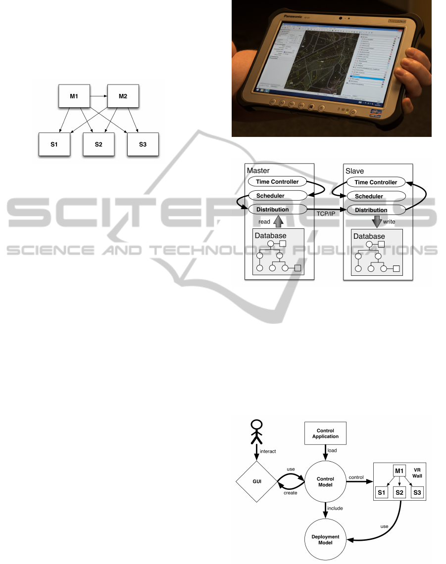
Figure 7: A possible topology of master (labeled M) and
slave computer (labeled S) nodes in a distributed simulation.
Even at a single location the topology may change
depending on the current simulation. For example,
with larger models it may be desirable to use extra
computation nodes for calculation heavy tasks, such
as collision detection or dynamics simulation, trading
network latency for processor load on a master node.
Thus the network topology is not only location, but
also model dependent and should also be altered au-
tomatically.
Through the configuration in the deployment
model a master node has a list of corresponding slave
nodes, to which it can send the state changes. In our
simulation system the topology is part of the configu-
ration and we use the property system to serialize all
changes and transmit those via TCP/IP to the slave
node, where the same serialization tools are used to
change the local properties.
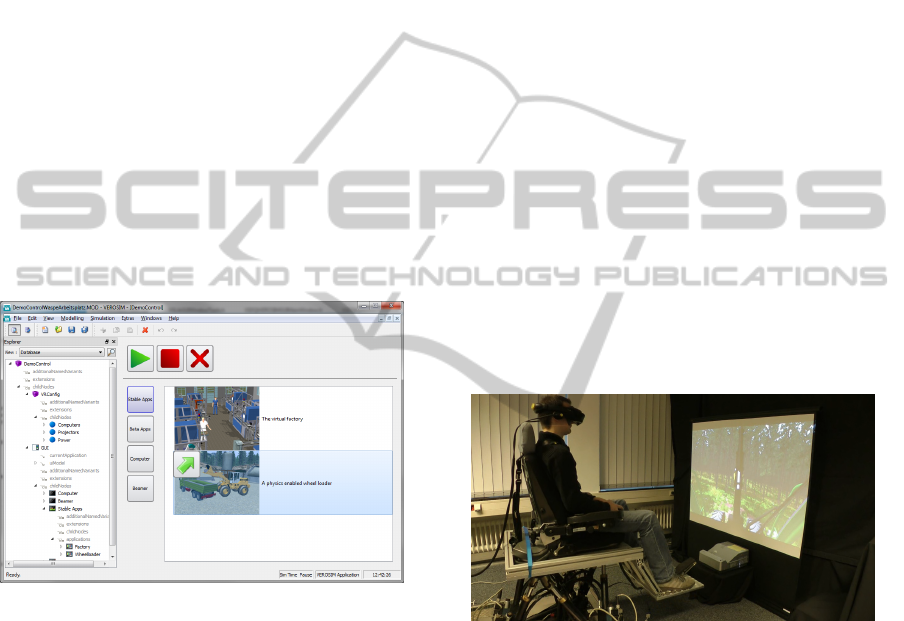
Figure 8 shows a forest simulation in desktop
mode. Even in this mode there exists a network topol-
ogy, consisting of one computer only, which is auto-
matically a master node. Since there are no associ-
ated receivers, the distribution plugin of the simula-
tion will be dormant. As shown in Figure 1 the forest
model is also executable on a multi-screen VR wall.
Figure 9 shows how a dedicated time controller
only triggers its associated scheduler when it receives
a time stamp signal from master computer. This time
controller is used automatically if the context of the
scheduler is set to Distribution-Receiver.
5.2 VR Environment Control
Due to its modular and flexible design a simulation
system based on an object-oriented graph database,
such as the VSD, can also be the foundation for non
simulation applications. It can be used in a separate
application to control and operate the VR environ-
Figure 8: A mobile computer running a forest simulation.
Figure 9: The time controller on a slave node is triggered
by an external signal.
ment and also act as another channel for user interac-
tion with the simulation. For this the VSD is extended
by the dark gray schema shown in Figure 5.
As shown in Figure 10, the model of the control
application contains the deployment model and adds
a GUI node and several user interface configuration
nodes.
Figure 10: The control flow for a VR wall.
When loaded the GUI node creates a sub model,
which is hidden to the end user. This sub model
in turn consists of a GUI description written in the
LocationBasedAlterationofSimulationModelsforMultiScreenVRApplications
107
state oriented modeling language (SOML) (Ross-
mann et al., 2013b), which when loaded becomes part
of the simulation database. A class in SOML can have
properties and invokable methods and can therefore
be interacted with just like a built-in schema class.
Since SOML is a language interpreted at run time, the
GUI can be altered by experts on site, without having
to recompile the application.
The GUI of the application shown in Figure 11
consists of a stack in which user defined widgets can
be inserted and a control widget, which is used to
start, stop and terminate the current simulation cho-
sen by the user. The layout of the control application
is determined by the GUI configuration nodes in the
loaded model. For each class of configuration nodes
there exists a corresponding SOML GUI class, which
upon the presence of such a configuration node in
the model is instantiated and inserted into the widget
stack. As an example a computer widget lists all com-
puter nodes found in the model and shows the current
connection and communication state of these comput-
ers.
Figure 11: The VR control application.
A special GUI configuration node is the applica-
tion GUI node, which has a reference property list of
applications nodes, each describing a simulation to be
used with the VR setup. To enforce their relation to a
GUI node, applications are not nodes and therefore
can not be children of another arbitrary node. An
application node has properties for the paths to the
executable and the model to be loaded, a reference
to the corresponding configuration and command line
parameters, as well as a path to an optional custom
GUI element written in SOML.
The control application strictly separates its func-
tionality from the user interface. All basic functional-
ity is handled by the VSD classes shown in Figure 5,
or classes derived from them.
When the control starts a simulation a two stage
process is started through the functionality of the ap-
plication node. On each computer listed in the com-
puter widget, a small TCP enabled application called
command server is running, which allows to start or
kill arbitrary process. First the control instructs the
command servers of the computers of the configura-
tion associated with an application to start a new in-
stance of the simulation system with a given config-
uration, command line arguments and model. Then
a simulation plugin called remote control protocol
(RCP) that can execute any invokable function of the
database through the meta information system opens
a second TCP port. This way the simulation scheduler
can be started or stopped, after the model is loaded.
If present, a custom GUI element is loaded for the
model. This GUI element is also added to the wid-
get stack and gets unloaded when the user quits the
simulation. This custom GUI can communicate with
the simulation via RCP or through any other channel,
such as a SOML script loaded by the simulation itself.
The configuration used for the control application
does not load any plugins related to any simulation
functionality, instead it consists of only the core, a file
loader, the SOML interpreter, the deployment model
plugin and a special control application plugin. For
creating and altering the model further editing wid-
gets may be loaded.
Figure 12: An advanced user interaction device. The user is
wearing a VR helmet, the screen is solely for spectators.
6 CONCLUSION AND FUTURE
WORK
In this paper we presented method for automatically
altering a simulation model, based on a separate, site-
dependent deployment model. It must be noted that
even though this paper focuses on the use of a partic-
ular simulation system that is well suited for the pro-
posed method, any flexible simulation software sys-
tem can benefit from using a location based deploy-
ment model.
With the use of a deployment model we have suc-
SIMULTECH2014-4thInternationalConferenceonSimulationandModelingMethodologies,Technologiesand
Applications
108

cessfully reduced the time for deploying new or up-
dated VR applications to several locations. If the de-
ployment model at the location is correct and com-
plete, the time is reduced to the download or check-
out from a versioning system.
The advantage in using a simulation system based
on a object-oriented graph database, that is capable
of run-time schema expansion, is the ability to base
the deployment model on the same core components,
thus making it usable in other second-use scenarios,
such as the control application.
As shown in Figure 12 we are currently working
on enhancing the simulation by optional robotic user
feedback mechanism, such as a state of the art KUKA
motion simulator (Bellmann et al., 2007) or a well
established Stewart platform as described in (Nanua
et al., 1990).
While these devices are obviously not available to
each developer, if used in a virtual testbed (Bardina
and Rajkumar, 2003) the control application can au-
tomatically start a a second simulation of the motion
hardware together with the primary simulation itself.
The developer can test the reaction of this hardware
to the input coming from the primary simulation, to
which it is indistinguishable, whether the hardware is
simulated or real, as long as both use the same method
of communication.
ACKNOWLEDGEMENTS
The work presented in this paper was done as part of
the Virtual Forest project.
The Virtual Forest project is co-financed by the
European Union and the federal state of North Rhine-
Westphalia, European Regional Development Fund
(ERDF). Europe - Investing in our future.
REFERENCES
(2000). IEEE Standard for Modeling and Simulation
(M&S) High Level Architecture (HLA) - Framework
and Rules. IEEE Std. 1516-2000, pages i –22.
Anders (2007). XML Path Language (XPath) 2.0. W3C
Recommendation.
Angles, R. and Gutierrez, C. (2008). Survey of graph
database models. ACM Computing Surveys, 40(1):1–
39.
Bardina, J. and Rajkumar, T. (2003). Intelligent launch
and range operations virtual testbed (ilro-vtb). In
AeroSense 2003, pages 141–148. International Soci-
ety for Optics and Photonics.
Bastide, R. (1995). Approaches in unifying petri nets and
the object-oriented approach. In In Proceedings of the
Application and Theory of Petri Nets.
Batkiewicz, T., Seth, A., Walter, B., and Martin, L. (2008).
A general architecture for distributed vr interfaces. In
Proceedings of the ASME 2008 International Design
Engineering Technical Conferences & Computers and
Information in Engineering Conference.
Bellmann, T., Otter, M., Heindl, J., and Hirzinger, G.
(2007). Real-time path planning for an interactive and
industrial robot-based motion simulator. In Proc. of
the 2nd Motion Simulator Conference.
Casanova, M. a., Breitman, K. K., Brauner, D. F., and
Marins, a. L. a. (2007). Database Conceptual Schema
Matching. Computer, 40(10):102–104.
Diestel, R. (2012). Graph Theory, 4th Edition, volume 173
of Graduate texts in mathematics. Springer.
Fujimoto, R. (2001). Parallel and distributed simulation.
Proceedings of the 2001 Winter Simulation Confer-
ence.
Gyssens, M., Paredaens, J., van den Bussche, J., and van
Gucht, D. (1994). A graph-oriented object database
model. Knowledge and Data Engineering, IEEE
Transactions on, 6:572 –586.
Henriksen, J. (1977). An improved events list algorithm.
Proceedings of the 9th conference on Winter simula-
tion . . . .
Marino, G. and Vercelli, D. (2007). Description and perfor-
mance analysis of a distributed rendering architecture
for virtual environments. Artificial Reality and . . . ,
pages 234–241.
Nanua, P., Waldron, K. J., and Murthy, V. (1990). Direct
kinematic solution of a stewart platform. Robotics and
Automation, IEEE Transactions on, 6(4):438–444.
Rossmann, J., Schluse, M., Schlette, C., and Waspe, R.
(2013a). A new approach to 3d simulation technology
as enabling technology for erobotics. In Van Impe, J.
F. M. and Logist, F., editors, 1st International Simula-
tion Tools Conference and EXPO 2013.
Rossmann, J., Schluse, M., and Waspe, R. (2013b). Com-
bining supervisory control, object-oriented petri-nets
and 3d simulation for hybrid simulation systems using
a flexible meta data approach. In
¨
Oren, T., Kacprzyk,
J., Leifsson, L., Obaidat, M. S., and Koziel, S., editors,
Proceedings of the 3rd International Conference on
Simulation and Modeling Methodologies, Technolo-
gies and Applications (SIMULATION TOOLS AND
PLATFORMS) - SIMULTECH 2013.
Tobler, R. F. (2011). Separating semantics from rendering:
a scene graph based architecture for graphics applica-
tions. The Visual Computer, 27(6-8):687–695.
LocationBasedAlterationofSimulationModelsforMultiScreenVRApplications
109
