Mixing and Combustion of Turbulent Coaxial Jets
An Application of Computational Fluid Dynamics to Swirling Flows
Teresa Parra
1
, Ruben Perez
1
, Miguel A. Rodriguez
1
, Artur Gutkowski
2
, Robert Szasz
3
and Francisco Castro
1
1
Department of Energy and Fluid Mechanics, University of Valladolid, Paseo del Cauce 59, 47011 Valladolid, Spain
2
Department of Heat Technology and Refrigeration, Technical University of Lodz, Lodz, Poland
3
Energy Division, Lund University, Lund, Sweden
Keywords: CFD, Swirl Number, Recirculation Zones, Burner.
Abstract: The aim of this research is gaining an insight into flow patterns in swirling burners. These are suitable for
lean mixtures, because of procuring the fix position of the flame. The interaction of the two reactive
confined swirling jets leads to the formation of complex patterns which are not well understood. In the
present study, these flow patterns are numerically investigated using Reynolds Averaging Navier-Stokes
(RANS) equations for the flow and a Probability Density Function is used for modelling the combustion.
Two swirl numbers were characterised: 0.14 and 0.74. Strong swirling annular jets are responsible of an
inner recirculation zone. Low swirling flows produce poorer mixture and wide flame fronts whereas strong
swirling flows are precursors of mixing enhancement and thing flame fronts.
1 INTRODUCTION
The paper is focused on studying the flow pattern of
the flame for low and high swirl number. Swirling
flows let burn lean mixtures near the flammability
limits and produce low emissions.
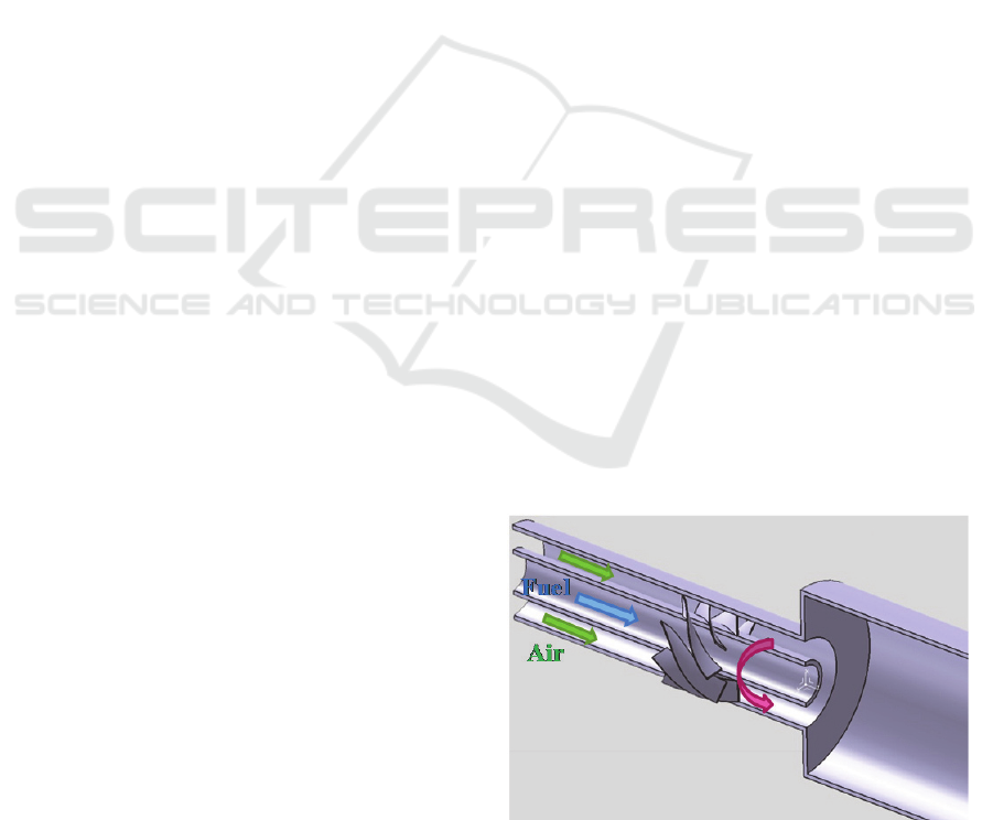
The simplest burners are based on the interaction
of two confined coaxial jets. Annular jet goes
through a swirler that gives azimuthal component to
the flow. The exit of the two coaxial nozzles to the
chamber with an expansion ratio of four in area
produces the separation of the annular boundary
layer. The swirling annular jet is responsible for the
radial pressure gradient. For swirl numbers over 0.6,
there is reverse flow in the centre of the chamber.
The benchmark of Roback and Johnson (Roback,
1983) is the set up chosen to study the influence of
the swirler. This burner has two coaxial nozzles that
discharge into a test chamber. Figure 1 shows and
scheme of the burner and table 1 presents a summary
of the main dimensions and operation conditions of
this test case.
The swirler is a certain number of fixed vanes
located in the annular nozzle. The change of the
trailing edge angle modifies the Swirl number of the
annular jet. This paper is devoted to study the flow
pattern of the flame for low and high swirl numbers.
Figure 1: Scheme of the Roback-Johnson swirling burner.
The definition of Swirl number is the ratio of
azimuthal momentum and axial momentum. The
clear classification of low and high swirl numbers is
related to the flow pattern.
Low-swirl injector (S < 0.6) produces in the test
chamber a Central Divergence Zone (CDZ), a Shear
Layer (SL) and an Outer Recirculation Zone (ORZ).
Whereas high-swirl injectors are precursors of an
Inner Recirculation Zone (IRZ), a Shear Layer (SL)
545
Parra T., Perez R., Rodriguez M., Gutkowski A., Szasz R. and Castro F..
Mixing and Combustion of Turbulent Coaxial Jets - An Application of Computational Fluid Dynamics to Swirling Flows.
DOI: 10.5220/0005009005450550
In Proceedings of the 4th International Conference on Simulation and Modeling Methodologies, Technologies and Applications (SIMULTECH-2014),
pages 545-550
ISBN: 978-989-758-038-3
Copyright
c
2014 SCITEPRESS (Science and Technology Publications, Lda.)
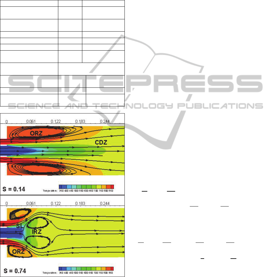
and an Outer Recirculation Zone (ORZ), (García-
Villalba, 2006
a
; García-Villalba 2006
b
). See figure 2
for details of the described flow pattern.
Table 1: Dimension details, boundary conditions and fluid
properties.
Fuel Oxidizer
Injection Central
Nozzle
Annular Nozzle
Nozzles' diameter
inner-outer (mm)
0-25 31-59
Composition CH
4
22% O
2
78% N
2
Temperature (K) 300 900
Velocity (m/s) 0.66 1.54
Turbulence intensity
(%)
12 7.5
Specific Heat(J/kg/K) Polynomial function of
temperature
Thermal Conductivity
(W/m/K)
0.0332 0.0242
Viscosity (kg/m/s) 1.087.10
-5
1.7894.10
-5
Molecular Weight
(kg/kmol)
16.04303 28.996
Figure 2: Contours of temperature in the longitudinal
plane and stream lines to locate recirculation zones for non
reactive cases.
The interest for swirling burners is based on their
low emissions and the possibility to burn lean
mixtures, (Parra, 2014; Parra 2015).
2 NUMERICAL MODEL
The three dimensional domain has the following
spatial resolution: ~d/190 in the test chamber,
~d/40 in the central nozzle and ~d/46 in the
annular nozzle, being d the diameter of the chamber,
diameter of central nozzle and difference of
diameters of the annular nozzle respectively, and
the dimension of the cell. To sum up, the
computational domain has around 10 million
hexahedral cells. The mesh is decomposed to be
solved in parallel being the criterion the minimum
number of cells in the interface to save
computational time associated to information
transfer.
Navier-Stokes equations for transient,
incompressible, turbulent and reactive flows were
solved using Total Variation Diminishing. Pressure-
Velocity coupling was PISO. Multigrid resolution
improves the performance towards the full
convergence.
Anisotropy of the swirling flow makes difficult
to model the turbulence. The chosen model was
RNG k-ε model dominated by the swirl. Because it
considers source term R
ε
based on the strain tensor,
(Versteeg, 1995). Its conservation equations are
described in equations (1) and (2).
(1)
(2)
Enhanced wall treatment is used as turbulence
treatment near the walls, hence the mesh was
generated for y
+
= 1.
SIMULTECH2014-4thInternationalConferenceonSimulationandModelingMethodologies,Technologiesand
Applications
546
2.1 Combustion Model
A suitable approach for turbulent non premixed
reacting flows is to use the mixture fraction defined
as a function of local mass fraction and their
corresponding in the combustible and oxidizer jets.
,
,
,
(3)
Local thermodynamic properties are predicted
from the mixture fraction distribution. Hence the
hypothesis of infinite Damköhler number is
assumed, that is instantaneous chemical reaction
after mixing is achieved, (Kuo, 1986). This method
let estimate intermediate species without solving a
detailed mechanism of reaction.
The code solves the transport equations for both
mixture fractions
̅
and the variance ′
as proposed
by Jones (Jones, 1982):
̅
̅
̅
(4)
′
′
̅
(5)
with
, C
g
and C
d
values equal to 0.7, 2.86 and 2
respectively.
The use of the Probability Density Function
(PDF) p(f) converts the time averaged mixture
fraction and variance,
̅
and ′
, into the
instantaneous mixture fraction f. The PDF can be
calculated assuming equilibrium or measured from
experiments. Finally, local temperature and
composition are evaluated as equation 6 where
∅
.represents either temperature or mass fractions.
∅
∅
(6)
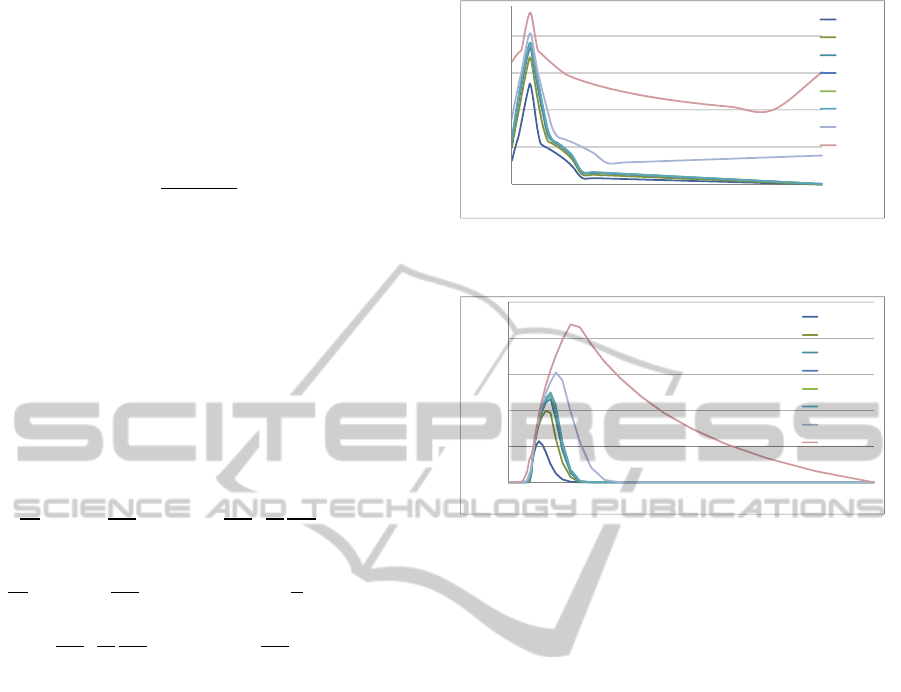
Figures 3 and 4 show the sample for temperature
and carbon monoxide at different scaled heat loss
(HL) or gain (HG) as well as adiabatic flames
obtained from experimental data and used for
simulations.
Figure 3: Tabulated temperature based on mixture fraction
and scaled heat loss-gain.
Figure 4: Tabulated CO mole fraction based on mixture
fraction and scaled heat loss-gain.
3 INFLUENCE OF SWIRL
NUMBER
In this section the flames for swirl numbers 0.14 and
0.74 are presented. Figure 5 depicts the mean
mixture fraction, as well as the volumes of null axial
velocity. Since the recirculation zones are composed
by negative values of axial velocity, these
isovolumes identify the boundaries of the
recirculation zones. Swirl = 0.14 presents a large
ORZ and lacks the IRZ. Whereas Swirl no. = 0.74
has a smaller ORZ and a central IRZ.
From the mixture fraction contours illustrated in
Figures 5, it is clear the higher gradients of any
variable are produced upwind of the IRZ. But for
Swirl no. 0.14, the mixture fraction gradient is lower
and the mixing region larger.
Figures 6 show the mixture fraction variance
whose local maxima correspond with the region with
high reaction rate. Swirl no. 0.14 has a larger
reaction zone than that of swirl no. 0.74. It is clear
the IRZ produces the blockage of the fuel jet, hence
it is forced to be deflected and mixed with the
annular jet. Also, the IRZ is mainly composed by
products of reaction that keep thermal conditions
adequate for ignition of the fresh mixture.
300
800
1300
1800
2300
00.20.40.60.81
MeanTe m p e r at u r e
MeanMixtureFraction
HL=‐48%
HL=‐19%
HL=‐8%
HL=‐3%
HL=‐1%
Adiabatic
HG=20%
HG=80%
0
0.05
0.1
0.15
0.2
0.25
0 0.10.20.30.40.50.60.70.80.9 1
MoleFractionofCO
MeanMixtureFraction
HL=‐ 48%
HL=‐ 19%
HL=‐ 8%
HL=‐ 3%
HL=‐ 1%
Adiabatic
HG=20%
HG=80%
MixingandCombustionofTurbulentCoaxialJets-AnApplicationofComputationalFluidDynamicstoSwirlingFlows
547
It is said that a flame with M shape tends to be
instable, whereas a flame with V shape is more
stable.
Figure 5: Longitudinal contours of Mean Mixture Fraction
for different swirl numbers. Grey shadows are the iso-
volume of null axial velocity.
Figure 6: Longitudinal contours of Mean Fraction
Variance. Grey shadows are the isovolume of null axial
velocity.
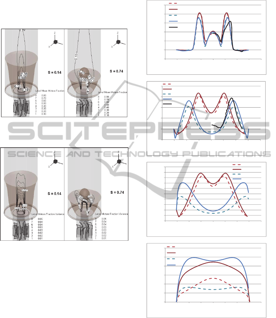
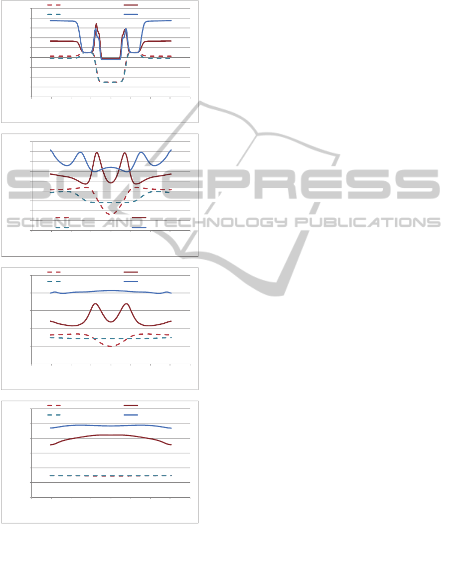
Figures 7 present the radial profiles of axial
velocity for non reactive and reactive cases and both
swirl numbers: 0.14 and 0.74. Simulations without
reactions are validated with the experimental results
provided by Palm (Palm, 2006).
Reactive cases (RXN) produce higher axial
velocities than non reactive cases (noRXN) because
there is a reduction of density in the reaction
products and there is mass conservation.
a)
b)
c)
d)
Figure 7: Radial profiles of axial velocities for different
sections. a) Z = 5mm, b) Z = 50mm, c) Z = 100 mm and d)
Z = 300 mm Experimental values from (Palm, 2006) for
no reactive case.
Negative axial velocities in the periphery of the
chamber are associated with the ORZ while these for
radial position near zero are involved with the IRZ.
‐0.5
0
0.5
1
1.5
2
2.5
‐0.08 ‐0.06 ‐0.04 ‐0.02 0 0.02 0.04 0.06 0.08
S=0.14noRXN
S=0.14RXN
S=0.74noRXN
S=0.74RXN
EXP_Palm
Tª[K]
R[m]
Vz[m/s]
R[m]
Z=5mm
‐0.5
0
0.5
1
1.5
2
‐0.08 ‐0.06 ‐0.04 ‐0.02 0 0.020.040.060.08
S=0.14noRXN
S=0.14RXN
S=0.74noRXN
S=0.74RXN
EXP_Palm
Tª[K]
R[m]
Vz[m/s]
R[m]
Z=50mm
‐0.4
‐0.2
0
0.2
0.4
0.6
0.8
1
1.2
1.4
1.6
‐0.08 ‐0.06 ‐0.04 ‐0.02 0 0.02 0.04 0.06 0.08
S=0.14noRXN
S=0.14RXN
S=0.74noRXN
S=0.74RXN
Tª[K]
R[m]
Vz[m/s]
R[m]
Z=100mm
0
0.2
0.4
0.6
0.8
1
1.2
‐0.08 ‐0.06 ‐0.04 ‐0.02 0 0.02 0.04 0.06 0.08
S=0.14noRXN
S=0.14RXN
S=0.74noRXN
S=0.74RXN
Tª[K]
R[m]
Vz[m/s]
R[m]
Z=300mm
SIMULTECH2014-4thInternationalConferenceonSimulationandModelingMethodologies,Technologiesand
Applications
548
It is clear the IRZ is higher for no reactive case than
for the reactive one for swirl 0.74.
a)
b)
c)
d)
Figure 8: Radial profiles of temperature for different
sections. a) Z = 5mm, b) Z = 50mm, c) Z = 100 mm and d)
Z = 300 mm.
Figures 8 present the radial profiles of
temperature for non reactive case to analyse the
mixing, and reactive case.
For reactive cases, the maximum variance is
observed for S=0.14, whereas for S=0.74 the flame
is more compact in longitudinal direction with
smaller difference of the local maxima. Hence, the
flame is prone to instabilities with low Swirl
numbers.
For reactive cases, the maximum variance is
observed for S=0.14, whereas for S=0.74 the flame
is more compact in longitudinal direction with
smaller difference of the local maxima. Hence, the
flame is prone to instabilities with low Swirl
numbers.
4 CONCLUSIONS
Computational Fluid Dynamics has been used to
study the interaction of two reactive confined
coaxial jets. Annular swirling jet was generated with
a swirl generator composed by 8 flat plates located
in the annular nozzle. Averaged fluid field for no
reactive case was validated with experimental results
provided by Palm (Palm, 2006). Inner and outer
recirculation zones where identified.
Low and high swirl injectors have been
simulated and their pattern flow was contrasted.
Numerical simulation uses PDF for combustion
model and RNG k-ε turbulence model. These were
found in this study to be suitable for turbulent swirl
dominated flows.
Low swirling injectors does not promote the
fluid to turn over near the centre of the chamber,
resulting larger mixing zones with weak gradients of
temperature and species' mass fractions.
Large swirling flows promote the formation of a
vortex bulb near the axis of the chamber. The
presence of the IRZ is a precursor of a smaller ORZ.
The lead stagnation point of the inner
recirculation zone is responsible of deflecting the
flame front and increases the mixing upstream of its
lead stagnation point.
ACKNOWLEDGEMENTS
The author thankfully acknowledges the Spanish
Ministry of Science and Innovation for the financial
resources in the framework of the project reference
ENE2011-25468.
0
200
400
600
800
1000
1200
1400
1600
1800
‐0.08 ‐0.06 ‐0.04 ‐0.02 0 0.020.040.060.08
S=0.14noRXN S=0.14RXN
S=0.74noRXN S=0.74RXN
Tª[K]
R[m]
Tª[K]
R[m]
Z=5mm
0
200
400
600
800
1000
1200
1400
1600
1800
‐0.08 ‐0.06 ‐0.04 ‐0.02 0 0.02 0.04 0.06 0.08
S=0.14noRXN S=0.14RXN
S=0.74noRXN S=0.74RXN
Tª[K]
R[m]
Tª[K]
R[m]
Z=50mm
0
500
1000
1500
2000
2500
‐0.08 ‐0.06 ‐0.04 ‐0.02 0 0.020.040.060.08
S=0.14noRXN S=0.14RXN
S=0.74noRXN S=0.74RXN
Tª[K]
R[m]
Tª[K]
R[m]
Z=100mm
0
500
1000
1500
2000
2500
3000
‐0.08 ‐0.06 ‐0.04 ‐0.02 0 0.020.040.060.08
S=0.14noRXN S=0.14RXN
S=0.74noRXN S=0.74RXN
Tª[K]
R[m]
Tª[K]
R[m]
Z=300mm
MixingandCombustionofTurbulentCoaxialJets-AnApplicationofComputationalFluidDynamicstoSwirlingFlows
549

We acknowledge PRACE for awarding us access
to resource Curie-GENCI@CEA based in France
and MareNostrum@BSC based in Spain. Ref.
2010PA1766
REFERENCES
García-Villalba M., Fröhlich J. and Rodi W. 2006
a
Identification and analysis of coherent structures in the
near field of a turbulent unconfined annular swirling
jet using large eddy simulation- Physics of Fluids
(1994-present) 18:5, 055103
García-Villalba M., and Fröhlich J. 2006
b
. LES of a free
annular swirling jet–Dependence of coherent
structures on a pilot jet and the level of swirl.
International journal of heat and fluid flow 27:5, 911-
923
Jones W., Whitelaw J., 1982. Calculation Methods for
Reacting Turbulent Flows: A Review. Combustion
and Flame vol. 48 pp1-26.
Palm R., Grundmann S., Weismuller M., Saric S., Jakirlic
S., Tropea C., 2006. Experimental characterization and
modelling of inflow conditions for a gas turbine swirl
combustor. International Journal of Heat and Fluid
Flow 27 924–936.
Parra T., Vuorinen V., Perez R., Szasz R. and Castro F.
2014. Aerodynamic characterization of isothermal
swirling flows in combustors. International Journal of
Energy and Environmental Engineering 5:85
Parra-Santos M. T., Mendoza-Garcia V., Szasz R. Z.,
Gutkowski A. N., Castro-Ruiz F. 2015. Influence of
swirling on the aero-thermodynamic behaviour of
flames. Combustion Explosion and Shock Waves
Accepted for publication on 23/5/14.
Kuo K., 1986. Principles of Combustion. John Wiley and
Sons.
Roback R., Johnson B.V. 1983. Mass and momentum
turbulent transport experiments with confined swirling
coaxial jets, NASA CR-168252
Versteeg H. K., Malalasekera W. 1995. Computational
Fluid Dynamics, The finite volume method.
SIMULTECH2014-4thInternationalConferenceonSimulationandModelingMethodologies,Technologiesand
Applications
550
