
Scenario Development: A Model-Driven Engineering Perspective
Umut Durak
1
, Okan Topçu
2
, Robert Siegfried
3
and Halit Oğuztüzün
4
1
Institute of Flight Systems, German Aerospace Center (DLR), Lilienthalplatz 7, Braunschweig, Germany
2
Department of Computer Engineering, Naval Science and Engineering Institute, Istanbul, Turkey
3
Aditerna GmbH, Riemerling, Germany
4
Department of Computer Engineering, Middle East Technical University, Ankara, Turkey
Keywords: Scenario Development, Distributed Simulation, Base Object Model, Model-Driven Engineering.
Abstract: Scenario development starts with capturing scenarios from the users and leads to the design and the
development of the simulation environment to execute these scenarios. This paper proposes a scenario
development process adopting a Model-Driven Engineering (MDE) perspective. It takes scenario
development and the use of scenarios in simulation environment development put forth in IEEE
Recommended Practice for Distributed Simulation Engineering and Execution Process (DSEEP) as a
starting point. It then constructs a basic vocabulary including the definitions of operational, conceptual, and
executable scenarios. Following MDE principles, scenario development is viewed as a series of model
transformations. Operational scenarios, mostly defined in a natural language, are first transformed into
conceptual scenarios, which conform to a formal metamodel. Then conceptual scenarios can be transformed
into executable scenarios specified using a specific scenario definition language. Furthermore, it is also
possible to generate the constructs of simulation environment design and development using model
transformations. In this regard, a conceptual scenario metamodel is proposed adopting the Base Object
Model metamodel as an example. Then this metamodel is used to present the proposed process with a
sample operational scenario and conceptual scenario excerpts. Samples are shown how model
transformation can be employed for developing a Federation Object Model and an executable scenario file.
1 INTRODUCTION
Although the importance of scenarios in modelling
and simulation has long been well known, there still
exists a lack of common understanding and
standardized practices in simulation scenario
development. Scenario development starts with
eliciting scenarios from the users and leads to
physical scenario data representation for runtime
execution and constraints to simulation environment
design.
Scenario development is an extensive process
beginning with the stakeholders’ descriptions of the
scenario and finishing with the generation of the
corresponding executable specifications. The
scenario development is a part of the simulation
environment development process. The scenario
development aims at developing a specification of a
simulation run, but it is also an input for the design
and development of the simulation environment
itself.
Siegfried and his colleagues propose to
distinguish three types of scenarios that are produced
in successive stages of the scenario development
process: operational scenarios, conceptual scenarios
and executable scenarios (Siegfried et al., 2012)
(Siegfried et al., 2013) (MSG-086, 2014).
In this paper Siegfried’s definitions are used as a
baseline for devising a model-driven scenario
development process. This process involves
establishing a scenario development pipeline. It
adopts Model-Driven Engineering (MDE). MDE
proposes that one shall construct a model of the
system to be built and then proceed with a series of
transformations to obtain an executable system
(Mellor et al., 2003). Following the principles of
MDE, scenario development is viewed as the
transformation of operational scenarios (defined in a
natural language) to conceptual scenarios
(conforming to a formal metamodel) then to
executable scenarios (specified using a specific
scenario definition language) and simulation
117
Durak U., Topçu O., Siegfried R. and Oguztüzün H..
Scenario Development: A Model-Driven Engineering Perspective.
DOI: 10.5220/0005009501170124
In Proceedings of the 4th International Conference on Simulation and Modeling Methodologies, Technologies and Applications (SIMULTECH-2014),
pages 117-124
ISBN: 978-989-758-038-3
Copyright
c
2014 SCITEPRESS (Science and Technology Publications, Lda.)

environment design (defined in a particular
formalism).
After introducing the required background
information, the proposed model-driven scenario
development process is presented. Then the process
is illustrated with a simple example.
2 BACKGROUND
The definition of scenario has long been a subject of
discussion. Siegfried et al. (Siegfried et al., 2012)
define a scenario as a specification of conditions and
situations to be represented by a simulation
environment for its purpose.
In IEEE 1278 (IEEE, 1993), the standard for
Distributed Interactive Simulation, a scenario is
defined as the description of initial conditions and
timeline of significant events. The definition given
in the High Level Architecture Glossary (US
Department of Defense, 1996) stresses that a
scenario shall identify the major entities with their
capabilities, behavior and interactions over time with
all related environmental conditions. The NATO
Science and Technology Organization Modeling and
Simulation Group 053 (MSG-053, 2010) defines a
scenario as a description of the hypothetical or real
area, environment, means, objectives and events
during a specified time frame related to events of
interest.
The operational scenarios are provided in the
early stages of a simulation environment
development process by the user or the sponsor. The
operational scenarios can be documented in any
textual or graphical form. The key elements in a
scenario are the initial state, the desired end state,
the course of actions to reach the prescribed end
state, and the entities with their capabilities and
relations.
The operational scenarios provide a coarse
description of the intended situation and its
dynamics, but they need to be refined and
augmented with additional information pertaining to
simulation. This refinement is usually done by M&S
experts and results in conceptual scenarios.
Conceptual scenarios provide a detailed
specification of the piece of the world to be
represented in the simulation environment and
should provide crucial information for everyone who
is involved in the later stages of the simulation
environment engineering process.
Once a simulation environment is designed and
set up, the executable scenarios have to be available
for all simulation systems and other member
applications of the simulation environment. For this
purpose, the conceptual scenarios need to be
transformed into executable scenarios. An
executable scenario is the specification of a specific
situation providing all information necessary for the
preparation, initialization, and execution of a
simulation environment and for supporting scenario
management activities such as scenario distribution
and role casting (Topçu & Oğuztüzün, 2010). The
transformation from conceptual scenarios to
executable scenarios is undertaken primarily by the
operator of the member applications of the
simulation environment (possibly assisted by M&S
experts or subject matter experts). Ideally, the
resulting executable scenarios are specified in a way
that they are directly processable by the member
applications (e.g. as a file containing parameters or
via a web service).
3 DEVELOPMENT PROCESS
A standard perspective for the utilisation of
scenarios in simulation development and execution
is introduced in IEEE Recommended Practice for
Distributed Simulation Engineering and Execution
Process (DSEEP) (IEEE, 2010a). DSEEP describes
a process framework for development and execution
of distributed simulation environments. The DSEEP
recommends scenario development activity as a part
of the problem conceptual analysis. The outcome of
this activity is defined as the major entities that must
be represented in the simulation environment,
description of their capabilities, behaviors and
relationships, event timelines, the environment, and
the initial and terminal conditions. The DSEEP then
prescribes the utilization of scenarios: a) for the
design of a simulation environment and for the
design of the member applications, and b) for
designing and establishing the simulation
environment agreements in simulation environment
development. These agreements enable the
simulation applications to interoperate. From an
HLA perspective, this corresponds to defining
federates, a Federation Object Model (IEEE, 2010b),
and Federation Agreements (Johns Hopkins
University Applied Physics Laboratory, 2010).
MDE has also been employed in systems
development in the simulation domain to generate
elements of a simulation system or simulation
environment from models via model transformations
(Topçu et al., 2008) (Adak et al., 2009) (Gaševic et
al., 2009) (Durak et al., 2009) (Tolk, 2002)
(Cetinkaya et al., 2011). The MDE methodology is
SIMULTECH2014-4thInternationalConferenceonSimulationandModelingMethodologies,Technologiesand
Applications
118
regarded as a natural continuation of the advances in
raising abstraction level for systems development to
boost productivity as well as quality (Atkinson &
Kuhne, 2003). The models are refined and
transformed during the development process until an
executable artifact is obtained.
Adopting this MDE definition for scenario
development, the authors propose a development
process in which conceptual scenarios are specified
based on a metamodel and then executable scenarios
for various target simulation systems are generated
via model transformations employing transformation
rules specified for those particular targets.
Conforming to the process model recommended
by DSEEP, we promote the construction of the
conceptual scenarios as models and the utilization of
model transformations for designing member
applications, environment agreements and
executable scenarios.
4 METAMODELING
MDE worldview is founded on models and
transformations among them. In order to describe a
model, one needs a language. One way to provide a
language is metamodeling. The Object Management
Group (OMG) introduced a four-level metamodeling
architecture, which specifies four levels: Information
(M0), Model (M1), Metamodel (M2) and Meta-
metamodel (M3), and their relations (OMG, 2011b).
M0 consists of the data to be described. M1
comprises the model that describes the data. M2
describes the structure and the semantics of the
model and named as metamodel and M3 is the top
level that specifies the structure and the semantics of
the metamodel and named as meta-meta model.
The proposed model-driven scenario
development process is structured upon this four-
layer metamodeling architecture of OMG. The
process advocates constructing a Conceptual
Scenario Metamodel prior to developing conceptual
scenarios. The aim is to start with a metamodel to
enable building a conceptual model and then to
support the model transformations from the source,
conceptual scenario to target simulation application
design, simulation environment agreements, and
executable scenario.
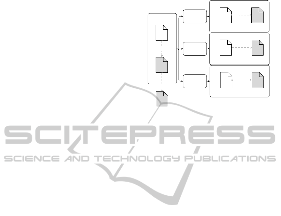
Figure 1 exemplifies the proposed process. It
recommends to develop a completely new
metamodel or to use an existing one for the shown
targets depending on the simulation environment
development process. The representations of target
models depend on the specification languages used
ConceptualScenario
Model
ConceptualScenario
Metamodel
Conformsto
ECORE
Meta‐metamodel
Conformsto
SimulationApplication
Design
UML
Metamodel
Conformsto
SOU R CE
Transformation
T2
Transformation
T1
Transformation
T3
SimulationEnvir onm ent
Agreement
FOM
Metamodel
Conformsto
ExecutableScenario
Model
MSDL
Metamodel
Conformsto
Figure 1 Model-Driven Scenario Development Process.
as depicted in the exemplified transformations in
Figure 1. For instance, the design of a simulation
application can be specified by using a general
modeling language such as UML, or by using a
more specific representation which targets a specific
platform such as Federation Architecture Metamodel
(FAMM) for HLA federations (Topçu et al., 2008).
If the UML metamodel is the target the
transformation rules will be specified from the
Conceptual Scenario Metamodel to the UML
metamodel. If HLA Object Models for environment
agreement are used, then FOM metamodel is the
target. Lastly, one can use specific scenario
definition languages such as the Military Scenario
Definition Language (MSDL) (SISO, 2008) as the
target metamodel for executable scenarios.
In the proposed scenario development process,
the conceptual scenario is subject to either model-to-
model or model-to-text transformations. To
accomplish these transformations, one needs to
specify the mappings between the constructs of the
source metamodel and those of the target
metamodel. Then a source model is transformed into
a target model by executing the specified
transformation (Gronback, 2009).
5 SAMPLE IMPLEMENTATION
In this section, the process introduced in the
previous section will be elaborated using a sample
implementation. In this implementation, we will first
introduce metamodeling over a conceptual scenario
metamodel that has been constructed adopting Base
Object Model (BOM) (SISO, 2006) metamodel.
Eclipse Modeling Framework (EMF) is
ScenarioDevelopment:AModel-DrivenEngineeringPerspective
119
employed to realize the four-level metamodeling
architecture. EMF is defined as a framework for
describing models and then generating other
constructs, such as other models, code or text from
them (Steinberg et al., 2008).
Next, a sample conceptual scenario vignette will
be introduced using the conceptual scenario
metamodel. Finally, transformation definitions will
be discussed over the sample mappings for
generating FOM and the executable scenarios from
the conceptual scenario.
5.1 Conceptual Scenario Metamodel
Base Object Model (BOM) introduces the interplay,
the sequence of events between simulation elements,
as well as the reusable pattern, and provides a
standard to capture the interactions (SISO, 2006).
Siegfried and his colleagues presented BOMs as a
method for capturing conceptual scenarios (Siegfried
et al., 2013). Following this approach, we adopt the
BOM metamodel specified in the standard to
construct a conceptual scenario metamodel.
Ecore is provided as the meta-metamodel used to
describe metamodels in EMF (Steinberg et al.,
2008). To define a metamodel, one makes use of
four Ecore classes, namely, EClass, EAttribute,
EReference and EDataType. EClass is defined as the
modelled class with attributes and references.
EAttribute is the modelled attribute with a name and
a type. EReference is specified as an association
between classes. EDataType is the type of an
attribute (Steinberg et al., 2008).
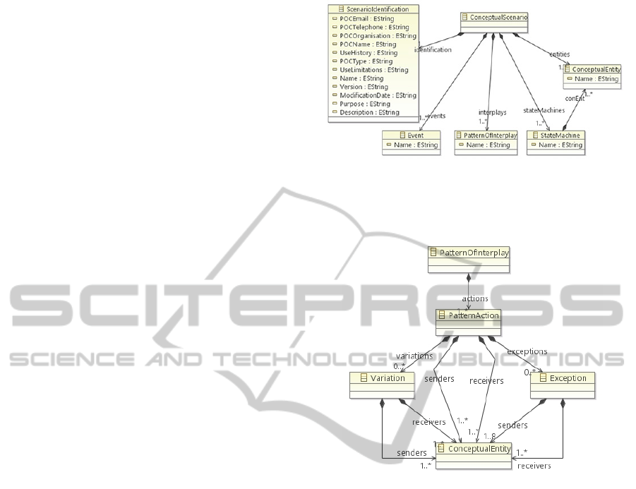
At the top level (Figure 2) ConceptualScenario,
defined as an EClass, has associations that are
defined by EReference constructs: entities,
stateMachines, interplays, events and identification.
These relate ConceptualScenario to other EClasses
Conceptual Entity, StateMachine, PatternOf
Interplay, Event and ScenarioIdentification,
respectively.
ScenarioIdentification has attributes that are
defined by POCEmail, POCTelephone and so on as
EAttributes. As an example the Purpose attribute is
defined as a string (EString) data type (EDataType).
A conceptual scenario is defined with one or
more state machines. A state machine is defined by a
number of states. Each state has an exit condition
and a next state. Exit conditions are associated with
exit actions that are pattern actions. For example, in
a flight simulation, the aircraft conceptual entity
may have six states: taxi, takeoff, climb, cruise,
descend and landing. The exit condition for taxi can
be defined as the takeoff clearance given by the
Figure 2: Conceptual Scenario Metamodel Top Level
Diagram.
control tower. Then takeoff can be specified as the
next state.
Figure 3: Pattern of Interplay in Conceptual Scenarios.
Patterns of interplay are defined as building blocks
in the BOM specification (SISO, 2006). They
capture the pattern actions as well as their
exceptions and variations. As shown in Figure 3,
actions are initiated by sender conceptual entities
and receivers are the intended recipients. Exceptions
are defined as the actions that cause the remaining
sequence to fail. Variations, however, are defined as
alternative ways of an action that do not affect the
completion or success. Considering again the case of
an aircraft, the pattern of interplay for the departure
is likely to include the aircraft beginning to roll from
its parking position in the direction of the assigned
runway. Depending of the parking position (in front
of the Terminal or further away on the Apron) an
initial push-back might be required or not, which can
be introduced as a variation of this action. The
sender for the taxiing can be specified as the pilot
and the receiver as the aircraft. The second action
can then be defined as getting the clearance from the
control tower. The sender in this case is the control
tower and receiver is the pilot and the event is the
takeoff clearance. And the pattern of interplay can
SIMULTECH2014-4thInternationalConferenceonSimulationandModelingMethodologies,Technologiesand
Applications
120
continue with an action of applying power to the
aircraft’s engine.
In BOM metamodel, conceptual entities take part
in patterns of interplay as senders and receivers and
each entity is associated with a state machine.
Entities possess characteristics and the BOM
metamodel is enhanced by adding values to these
characteristics to define scenario parameters. For
example, various characteristics can be specified for
an aircraft entity in a flight simulation scenario,
some of which are initial position, fuel weight or
gross weight. The values of these characteristics
then determine the scenario parameters.
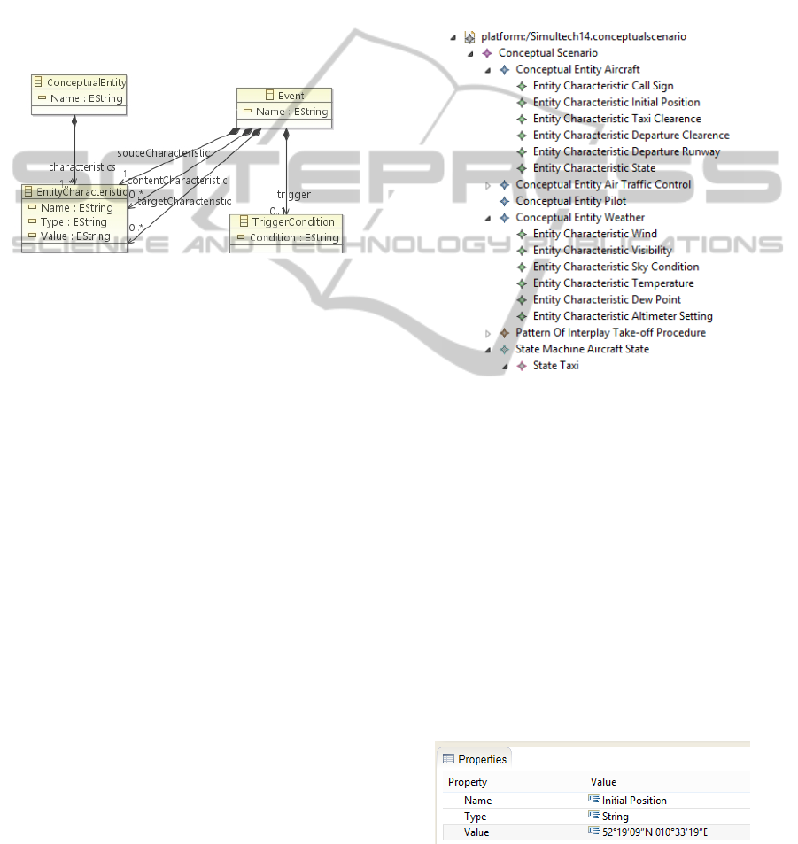
Figure 4: Conceptual Entities and Events in Conceptual
Scenarios.
Events (Figure 4) are used to capture the messages
and triggers. Triggers present undirected events
when a change in the characteristic of an entity
creates a response from other entities. The condition
of change is captured in a trigger condition.
Messages are directed events from one entity to
another that are uniquely identified by the source
and target characteristic. The content of a message is
given in content characteristics. As an example,
takeoff clearance is a message from tower (which is
identified by its airport id) to an aircraft (which is
identified by its call sign). The content of the
message is the takeoff clearance characteristic of the
aircraft. When the takeoff characteristic of an
aircraft is true, then it is a trigger event. Then the
pilot entity can start an action for gears up.
5.2 Model-Driven Conceptual Scenario
Development
This section is based on an operational scenario for
the departure activity of an aircraft. Below is an
extract from the operational scenario.
“Aircraft D-ATRA stands in front of its hangar at
DLR in Braunschweig. Pilots ask the tower for taxi
clearance. The tower provides taxi instructions
towards RWY 08. Pilots then start taxiing according
to instructions. Then tower provides information
about the departure like weather, VRB05KT,
R08/2800FT, overcast sky. Then pilots ask for a
departure clearance and tower grants the
departure.” (DFS Deutsche Flugsicherung GmbH,
2013) (Ahmad & Sexana, 2008).
This is an example operational scenario one can
obtain from the users or sponsors of a flight
simulator. It is obvious that not all data that is
required to run this scenario is available in this text.
An M&S expert needs to augment the missing
information and to develop a conceptual scenario.
Figure 5: Conceptual Scenario Editor Tree Viewer.
EMF.Edit (Steinberg et al., 2008) is employed to
build conceptual scenario editor via automatic code
generation to display and edit the instances of the
developed metamodels. This editor provides a tree
viewer and properties sheet for each conceptual
scenario element. Figure 5 presents the tree viewer
for the sample conceptual scenario. The tree presents
some of the conceptual entities from the operational
scenario such as aircraft, pilot, and weather. The
main pattern of interplay is defined as takeoff
procedure. Aircraft state is captured as a statechart.
When developing the conceptual scenario, missing
weather characteristics in operational scenario such
as temperature and dew point are also added to the
model.
Figure 6: Conceptual Scenario Editor Properties Viewer.
ScenarioDevelopment:AModel-DrivenEngineeringPerspective
121
The Properties viewer (Figure 6) enables a user
to specify the attributes of the model elements. As
an example, the attributes of initial position entity
characteristics are its name (initial position), type
(string), and value (52°19′09″N 010°33′19″E). Thus
an M&S expert can specify the implicit reference to
the initial location of the aircraft in the operational
scenario explicitly.
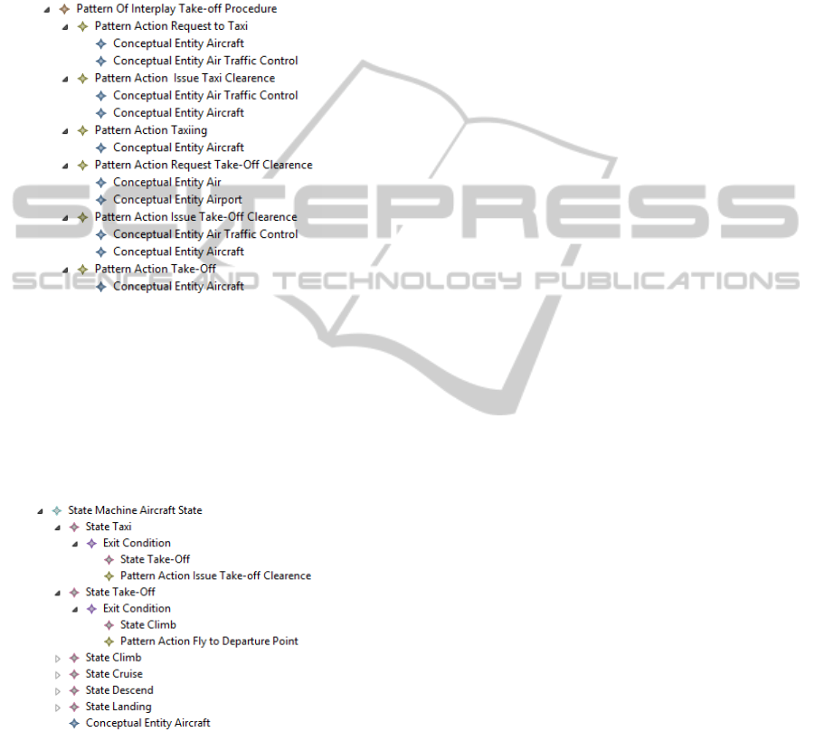
Figure 7: A Sample Pattern of Interplay.
The takeoff procedure is presented in Figure 7 as a
sample pattern of interplay. There are six
consecutive actions, starting from “aircraft requests
to taxi from Air Traffic Control” till its takeoff. The
sender and receiver entities are all captured. Even
though exceptions and variations can be specified,
this sample does not exhibit any.
Figure 8: A Sample State Machine.
Figure 8 introduces a sample aircraft state machine.
Aircraft states include taxi, takeoff, climb, cruise,
descend and landing. The next state after taxi is
takeoff and the exit action of the taxi state is the
issue of takeoff clearance. The next state after
takeoff is climb and takeoff ends with the action
flying to departure point.
5.3 Model Transformations
Model transformations are the enabling tools of
MDE for development. Throughout the engineering
process, models are the main artifacts, and
transformations enable the reflection of the
information captured in one model to another one as
well as enriching the source model with specialized
information. In the model-driven scenario
development process model transformations are
proposed for transforming the information that is
captured in a conceptual model to simulation
environment design, simulation environment
agreements and executable scenarios. To define
transformations from a source metamodel to a target
metamodel, a model transformation language is
required. Atlas Transformation Language (ATL)
(Jouault et al., 2006), Graph Rewriting and
Transformation (GReAT) (Agrawal, 2003) and
Query / View / Transformation (QVT) (OMG,
2011a) are some of the commonly used languages.
Rather than addressing any specific model
transformation language, users are recommended to
pick any model transformation language that fits
their specific requirements such as the development
environment requirements or target model
requirements.
Here, the sample transformation specification, or
mapping, was developed using QVT utilizing
Eclipse Model-to-Model Transformation (MMT)
project (The Eclipse Foundation, 2014). It supports a
QVT Operational, a partial implementation of the
QVT specification (Barendrecht, 2010).
-- model type definition to conceptual --
scenario metamodel
modeltype CS uses 'ConScen.ecore';
-- model type definition to UML
modeltype UML uses 'SimpleUML.ecore';
-- transformation definition from
-- Conceptual Scenario to UML
transformation scenario2UML(in CS :
ConSce, out UML);
-- main triggers the transformation
main(in scenario: CS::ConSce,
out umlModel: UML::Model)
{
umlModel := scenario.map scen2UML ();
}
As presented above, QVT defines
transformations using a certain structure, which
consists of model type definitions, transformation
declarations, and a main function. Metamodels are
referred by using model type definitions.
Transformation declarations specify the input and
the output metamodels. The main function starts the
transformation process by calling the first
transformation.
SIMULTECH2014-4thInternationalConferenceonSimulationandModelingMethodologies,Technologiesand
Applications
122

Mappings specify which object from an instance
of a source metamodel will be transformed to which
specific object in the instance of the target
metamodel. The declarations identify the source
class name and the target class name. One can also
specify constraints to mappings using Object
Constraint Language (OCL) (OMG, 2006). In the
body of a mapping, the variables and the parameters
are initialized in the init section, mappings are
specified in the population section and post-
processing can be done in the end section.
mapping CS::CS:: scen2UML() : UML::Model
{
init { log("Mapping Started!"); }
packages := self.entities2packages();
interfaces := self.entChar2intClasses();
states := self.states2staClasses();
...
end { log("Mapping Ended!"); }
}
Above is a representative excerpt from the top
level mapping that is called in the main function.
Conceptual entities in the conceptual scenario
metamodel are mapped to packages in the UML
model calling a new mapping function
self.entities2packages(). Similarly, the entity
characteristics and the states in the conceptual
scenario metamodel are mapped to the interface
classes and to the state classes, respectively, in the
UML model.
mapping CS::CS:: scen2FOM() : FOM::Model
{
...
objects := self.entities2objects();
objectAttr := self.entChar2objAttr();
interactions := self.events2intact();
intParam := self.contChar2intParam();
...
}
Likewise, a sample portion is provided for the
conceptual scenario to Federation Object Model
transformation. In this case entities can be mapped
to HLA objects and entity characteristics to object
attributes. Events in the conceptual scenario
metamodel can be mapped to HLA interactions in a
FOM and content characteristics to interaction
parameters.
mapping CS::CS:: scen2EXE() : EXE:File
{
...
entitites := self.entities2entities();
initialCond := self.entChar2iniCond();
injectEvents := self.events2inject();
logData := self.states2logging();
...
}
For a transformation to create an executable
scenario from a conceptual scenario, mappings need
to be specified as exemplified above. Entities in the
conceptual scenario must be mapped to the entities
of the executable scenario.
6 CONCLUSIONS
This paper introduced a model-driven scenario
development process which is based on the explicit
specification of conceptual scenarios using a
metamodel. The proposed development process
recommends the use of model transformations to
generate the executable scenarios. Practitioners of
this process shall develop their metamodels for the
source (i.e. conceptual scenario) and target (i.e.
executable scenario, design of simulation
applications, or simulation environment
agreements).
The proposed process is illustrated with a
simplified case study. In this respect, BOM presents
a prospect in specifying the conceptual scenarios as
the source metamodel. Target metamodels on the
other hand are more or less application-specific. The
examples introduced in this paper made use of
Eclipse-based technologies for modeling and
transformation,although there exist alternatives to
Eclipse for each of these steps.
In order to elaborate on the proposed model-
driven scenario development process, an effort to
develop the corresponding workflows will be
worthwhile.
REFERENCES
Adak, M., Topçu, O. & Oğuztüzün, H., 2009. Model-
based Code Generation for HLA Federates. Software:
Practice and Experience, 40(2), pp.149-75.
Agrawal, A., 2003. GReAT: A Metamodel Based Model
Transformation Language. Institute for Software
Integrated Systems (ISIS), Vanderbilt University.
Ahmad, S. & Sexana, V., 2008. Design of Formal Air
Trafic Control System throug UML. Ubiquitous
Computing and Communication Journal, 3(6), pp.11-
20.
Atkinson, C. & Kuhne, T., 2003. Model-driven
development: A metamodeling foundation. IEEE
Software, 20(5), pp.36-41.
Barendrecht, P.J., 2010. Modeling transformations using
QVT Operational Mappings. Research project report.
Eindhoven: Eindhoven University of Technology
Department of Mechanical Engineering Systems
Engineering Group.
Cetinkaya, D., Verbraeck, A. & Seck, M.D., 2011.
MDD4MS: A Model Driven Development Framework
ScenarioDevelopment:AModel-DrivenEngineeringPerspective
123

for Modeling and Simulation. In Summer Simulation
Conference. The Hague, Netherlands, 2011.
DFS Deutsche Flugsicherung GmbH, 2013. Aerodome
Chart -ICAO Braunschweig-Wolfsbug. Langen: DFS
Deutsche Flugsicherung GmbH.
Durak, U., Oguztuzun, H. & Ider, K., 2009. Ontology
Based Domain Engineering for Trajectory Simulation
Reuse. International Journal of Software Engineering
and Knowledge Engineering, 9(8), pp.1109-29.
Gaševic, D., Djuric, D. & Devedžic, V., 2009. Model
Driven Engineering. In Model Driven Engineering
and Ontology Development. Berlin: Springer.
Gronback, R.C., 2009. Eclipse Modeling Project: A
Domain-Specific Language. Upper Saddle River, NJ:
Addison-Wesley.
IEEE, 1993. IEEE 1278 Protocols for Distributed
Interactive Simulation Applications-Entity Information
and Interaction. Standard. New York, NY: IEEE.
IEEE, 2010a. IEEE Recommended Practice for
Distributed Simulation Engineering and Execution
Process (DSEEP). New York, NY: IEEE.
IEEE, 2010b. IEEE Standard for Modeling and Simulation
High Level Architecture (HLA)– Object Model
Template (OMT) Specification. Standard. New York,
NY: IEEE.
Johns Hopkins University Applied Physics Laboratory,
2010. Live-Virtual-Constructive Architecture
Roadmap Implementation, Common Capabilities—
Federation Agreements Template Users’ Guide.
Technical Report. Laurel, MD: Johns Hopkins
University.
Jouault, F. et al., 2006. ATL: a QVT-like Transformation
Language. In OOPSLA '06. New York, 2006. ACM.
Mellor, S.J., Clark, A.N. & Futagami, T., 2003. Guest
editors' introduction: Model-driven development.
IEEE Software, 20(5), pp.14-18.
MSG-053, 2010. Rapid Scenario Generation for
Simulation Applications. RTO Technical Report.
Brussels: NATO.
MSG-086, 2014. Guideline on Scenario Development for
(Distributed) Simulation Environments. STO
Technical Report. Brussels: NATO.
OMG, 2006. Object Constraint Language, Version 2.0.
Standard. Needham, MA: OMC Object Management
Group.
OMG, 2011a. Meta Object Facility (MOF) 2.0
Query/View/Transformation Specification. Standard.
Needham, MA: OMG.
OMG, 2011b. Object Management Group, Meta object
facility,MOF specification version 2.4.1. Standard.
Needham, MA: OMG.
Siegfried, R. et al., 2012. Scenarios in military
(distributed) simulation environments. In Spring
Simulation Interoperability Workshop (S-SIW).
Orlando, 2012. SISO.
Siegfried, R. et al., 2013. Specification and documentation
of conceptual scenarios using Base Object Models
(BOMs). In Spring Simulation Interoperability
Workshop. San Diago, 2013. SISO.
SISO, 2006. SISO-STD-003-2006 Base Object Model
(BOM) Template Specification. Orlando, FL :
Simulation Interoperability Standards Organization
(SISO).
SISO, 2008. Standard for Military Scenario Definition
Language (MSDL). Standard. Orlando, FL : SISO.
Steinberg, D., Budinsky, F., Merks, E. & Paternostro, M.,
2008. EMF: Eclipse Modeling Framework. 2nd ed.
Upper Saddle River, NJ: Pearson Education.
The Eclipse Foundation, 2014. Model-to-Model
Transformation (MMT). [Online] Available at:
https://projects.eclipse.org/projects/modeling.mmt
[Accessed 10 February 2014].
Tolk, A., 2002. Avoiding another Green Elephant – A
Proposal for the Next Generation HLA based on the
Model Driven Architecture. In Fall Simulation
Interoperability Workshop. Orlando, FL, 2002.
Topçu, O., Adak, M. & Oğuztüzün, H., 2008. A
Metamodel for Federation Architectures. Transactions
on Modeling and Computer Simulation (TOMACS),
18(3), pp.10:1-10:29.
Topçu, O. & Oğuztüzün, H., 2010. Scenario Management
Practices in HLA-based Distributed Simulation.
Journal of Naval Science and Engineering, 6(2), pp.1-
33.
US Department of Defense, 1996. High Level Architecture
Glossary. US DoD: Washington DC, VA.
SIMULTECH2014-4thInternationalConferenceonSimulationandModelingMethodologies,Technologiesand
Applications
124
