
Model Integration Workflow for Keeping Models up to Date in a
Research Simulator
Torsten Gerlach, Umut Durak and Jürgen Gotschlich
Institute of Flight Systems, German Aerospace Center (DLR), Lilienthalplatz 7, Braunschweig, Germany
Keywords: Model Integration, Flight Simulators, Model based Design and Development, Simulink Coder.
Abstract: Flight simulators can be categorised as research simulators, engineering simulators and training simulators.
Research simulators can be introduced as both test beds for flight simulator research and computational
tools for flight systems and human factors research. While engineering simulators are utilised for systems
development, training simulators are used for flight training. The models that are used in training simulators
and also in engineering simulators are more mature and stable. On the other hand, the models in research
simulators are subject to a constant change. While Model Based Design and Software Development has
brought us agile model development workflows, so that modellers can update their models more easily, it
came up with some serious systems integration and testing problems, so systems developers need to
establish mechanisms to tackle frequent behaviour and interface changes. DLR’s Institute of Flight Systems
(FT) has a long tradition in flight research and simulation of various flight vehicles. Currently a modern
research simulator facility is being operated at DLR Braunschweig –AVES (Air Vehicle Simulator). AVES
is designed such that interchangeable cockpits of rotorcraft (EC135) and airplanes (A320) can be operated
on motion and fixed-base platforms according to the particular needs. 2Simulate is the enabling real-time
simulation infrastructure of the AVES. This paper presents 2Simulate model integration workflow based on
Mathwork’s Simulink Coder.
1 INTRODUCTION
Till late 1920s, when Edward Link built one of the
early examples of flight simulators, they have been
important elements of aviation. These first examples
which were known as Blue Box, were designed to
train pilots for instrumented flight (Allerton, 2009).
Before digital era, flight simulators became well
accepted as training aids by many aircraft operators.
Then as the fidelity of flight simulators increased,
engineering standards to build flight simulators for
flight training were developed.
As flight simulators became de facto tools in
flight training, they were also started to be used in
aircraft development. After 1980s, testing and
validation of aircraft systems started to be done in
engineering flight simulators. Thus, potentially
dangerous and expensive flight tests could be
avoided (Allerton, 1999).
In 80s, aeronautics research community was also
using flight simulators for developing and
experimenting advanced concepts. ATTAS
Simulator from German Aerospace Center (DLR)
(Saager, 1990) (Klaes, 2000), NASA Crew Vehicle
Systems Research Facility in Ames Research Center
(Sullivan & Soukup, 1996) and Visual Motion
Simulation and Cockpit Motion Facility from
Langley Research Center (Smith, 2000) were some
of the first examples of research flight simulators.
Some of the recent ones are Air Vehicle Simulator
(AVES) of German Aerospace Center (DLR) (Duda
et al., 2013), HELIFLIGHT from the University of
Liverpool (White & Padfield, 2006), NASA Ames
Vertical Motion Simulator (Advani et al., 2002) and
SIMONA of the Delft University of Technology
(Stroosma et al., 2003).
The organisation of a flight simulator is
structured around the flight dynamics model. There
may be various components that supports or works
with flight dynamics model, like aerodynamics
model, landing gears model, weather model, engine
model and subsystem models. The architecture of
these models varies from simulator to simulator.
They can either be implemented as a single model or
various models interacting in a tightly coupled
manner. The other important components like
125
Gerlach T., Durak U. and Gotschlich J..
Model Integration Workflow for Keeping Models up to Date in a Research Simulator.
DOI: 10.5220/0005011301250132
In Proceedings of the 4th International Conference on Simulation and Modeling Methodologies, Technologies and Applications (SIMULTECH-2014),
pages 125-132
ISBN: 978-989-758-038-3
Copyright
c
2014 SCITEPRESS (Science and Technology Publications, Lda.)

control loading, instructor station, motion system,
visual system, instrument displays either provide
inputs to these models or present their results to the
pilot as cues (Allerton, 2009).
Research simulators have been used as the test
beds for flight simulator, flight systems and human
factors research. So, while the models that are used
in training simulators and even in engineering
simulators are more mature and stable, the models in
research simulators are subject to a constant change.
Recent advances in Model Based Design and
Software Development (MBDSD) have brought
aeronautics community agile model development
workflows. So that model development is integrated
to product development employing mature code
generation practices (Ruff et al., 2012). Models
developed to design the products now became the
bases for code generation to be deployed in the
product.
For research flight simulators with MBDSD, the
models that are built to study overall systems (e.g.
Flight Dynamics Model) and subsystem (e.g. Flight
Warning Computer Model) behaviour became the
bases for generating code to be deployed in real time
flight simulators. These models serve for researchers
that exercise various aspects of aircraft in their
desktop environments, and for simulator developers
to simulate aircraft system and sub systems.
Research simulator developers need to establish
mechanisms to tackle frequent behaviour and
interface changes in models. And constant model
changes in a research habitat can only be enabled
with a model integration workflow in the systems
development. But flight simulator literature lacks in
reporting any efforts.
There are some recommended practices from the
aerospace industry for model based flight systems
design and development. Estrada et al. introduce
best practices for developing DO-178 compliant
software using Model-Based Design and
Development (Estrada, R.G. et al., 2013). Miller
presents automatic flight code generation practices
in Northrop Grumman (Miller, 2007) and introduces
a use case from desktop simulation to Hardware in
the Loop testing. BAE Systems has a model based
flight control systems development process
(Fielding, 2010). Fielding presents a process
starting from aerodynamic dataset generation to
flight clearance of the aircraft. In this process he
mentions the use of engineering simulators for
model based flight control system design. Nixon
states that in F-35 project MBDSD forced them to
reinterpret traditional software development process
for flight control systems (Nixon, 2004). He
introduces Lockheed Martin Aeronautics practices
of MBDSD.
On the other hand, there exists a vast amount of
effort to develop integration workflows for their
model based developed software component. In one
of them (Guido and Thompson, 2008) from Math-
works, authors propose a workflow to develop
software components to be integrated to Automotive
Open System Architecture (AUTOSAR).
AUTOSAR specifies the architecture to integrate
functional applications over a hardware abstracting
runtime environment in automotive electronic
control units. The presented workflow enables
modellers to develop an infrastructure compliant
model development and seamless integration over a
standard architecture.
Figure 1: DLR AVES.
DLR’s Institute of Flight Systems (FT) has a
long tradition in flight research and simulation of
various flight vehicles. Currently AVES, a modern
research simulator facility is being operated at DLR
Braunschweig. AVES is designed such that
interchangeable cockpits of rotorcraft (EC135) and
airplanes (A320) can be operated on motion and
fixed-base platforms according to the particular
needs. 2Simulate is the enabling real-time simulation
infrastructure of AVES. All simulator software
components are integrated over this infrastructure.
This effort adopts best practices from both aerospace
and automotive industries. It tackles the model
integration problem of research flight simulators by
developing a model integration workflow for the
indigenous simulator infrastructure, namely
2Simulate. The motivation is to contribute to flight
simulator development by introducing a model
integration workflow for institutionalizing MBDSD.
The paper presents the Mathwork’s Simulink
Coder based model integration workflow of
2Simulate infrastructure in AVES facility. This
workflow provides the users of AVES a shortened
time to simulator after they updated their models.
SIMULTECH2014-4thInternationalConferenceonSimulationandModelingMethodologies,Technologiesand
Applications
126
First the reader will be introduced to 2Simulate.
Following the presentation of proposed model
integration workflow, how the 2Simulate Model
Control is designed to enable this workflow will be
discussed. Sample model integration will then be
provided to exemplify the concepts and technologies
introduced.
2 2SIMULATE
AVES was developed based upon the strategy to
employ reusable, flexible, standardized and properly
validated software modules. 2Simulate is an overall
simulation framework to facilitate integrating a wide
range of models and simulation components like
external devices, data recorders or image generators.
(Gotschlich et al., 2014).
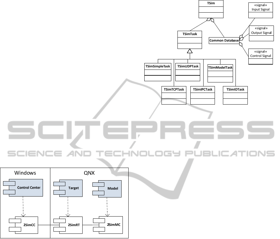
It is a C++ real-time distributed simulation
framework which is composed of three components,
namely 2Simulate Real-Time Framework (2SimRT),
2Simulate Model Control (2SimMC) and 2Simulate
Control Center (2SimCC) (Figure 2).
Figure 2: 2Simulate Components.
2SimRT is the core simulation framework of
2Simulate that provides deterministic scheduling and
controlling of real-time tasks. It comes as libraries
and API header files for Windows to support soft
real time implementations like desktop simulators,
or QNX to support hard real time implementations
like full flight simulators. Hard real time use case is
targeted in the scope of this paper. Any simulation
application that is based on 2SimRT is called a
Target. Targets possess various real-time tasks that
are implemented utilizing the 2SimRT API.
TSimModel is one of these real-time tasks used for
integrating Simulink models. Tasks can be
programmed using their pre- and post-initialization
and pre- and post-process callbacks. 2SimRT also
provides a Common Database to manage the data
flow through the internal and external interfaces
(Figure 3).
Figure 3: Main 2Simulate Classe.s
2SimMC is the enabler of model integration
workflow. It is composed of 2Simulate Model
Control Source (2SimMC-Source) that abstracts
model interfaces for 2SimRT, and 2Simulate Model
Control Scripts (2SimMC-Scripts) that includes
Simulink Coder Target Language Compiler files
(TLC files) to specify the 2Simulate target and m-
files to conduct the code generation and build
process.
2SimCC is the graphical user interface that is
configured to a Control Center for specific needs. It
is a Windows executable which can be customized
via configuration files called 2SimCC project files.
Control Center can run, pause or stop various
Targets. Besides, it accesses the Target Data
Dictionaries which can be defined as the data access
mechanisms and enables presenting or editing
Target data at runtime. It can also enable user
management to define and enforce user access
rights.
3 INTEGRATION WORKFLOW
Model integration workflow is triggered if any of the
simulator models in the simulator are updated. As
soon as the update is tested and verified in the
modeling environment, which is Matlab/Simulink,
the modeler would like to deploy it to its target. The
process assumes that the modeler assures that the
model is valid and correct.
Proposed workflow starts with a static model
checking step before continuing to generating source
code. Checking a model for modeling guidelines
will provide a set of valuable information about
what best practices or guidelines are violated. Thus
it contributes to the quality of the model (Fey and
ModelIntegrationWorkflowforKeepingModelsuptoDateinaResearchSimulator
127
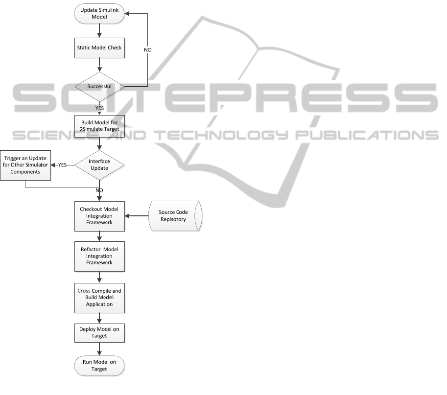
Stürmer, 2007). Measuring and assessing the quality
of the model for code generation has various aspects
including structured and automated testing, coverage
analysis, complexity analysis, modeling guidelines
(Stürmer and Pohlheim, 2012). Matlab Model
Advisor is employed as a starting point in this step
to check the mode for conditions and configurations
that may lead to generation of inaccurate and
inefficient code (The MathWorks, Inc., 2007) .
Figure 4: Model Integration Workflow.
As depicted in Figure 4, the next step is building
the model for 2Simulate target. The Simulink model
can be used with 2Simulate after it has been
converted into C++ code using Mathworks Simulink
Coder (The Mathworks, Inc., 2014a). A part of the
Simulink Coder is the Target Language Compiler. It
specifies the code generation (The Mathworks, Inc.,
2014b) utilizing so called system target files, which
can be customized for specific needs. 2Simulate has
such a set of customized system target files. They
embed 2SimMC into the model code during the code
generation. Thus, an auto-generated model is readily
available for 2Simulate model task. At this step,
these set of target files are employed. The details of
2Simulate system target files will be presented in the
next section.
The changes in the model interface are traceable
over the signal specifications for the model
generated, while code generation process. It is
almost clear that any change in the model interface
will cause an update in the other simulator
components that depend on these signals. So the
next step of the integration workflow is to trigger an
update process for the other components if any
change in the model interface is identified.
The next two steps in the process aims at
preparing the model application source project. At
first Model Integration Framework is checked out
from the source repository. This framework is a
wrapper for the generated model code. It creates a
2SimRT target using the generated model code. This
wrapper code is refactored automatically for model
specific parameters. As an example, the solver step
size of the model is set as the frequency of the model
task in the Model Integration Framework code. After
refactoring model application code is ready for
compilation.
The rest of the process is to cross-compile the
application code for the QNX target and deploy the
generated image to the target system. At the end of
the workflow, the updated model becomes readily
runnable at the target system.
4 2SIMULATE MODEL
CONTROL
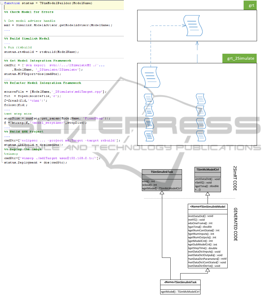
In this section, components of 2SimMC, 2SimMC-
Scripts and 2SimMC-Source will be introduced.
There are two types of scripts in 2SimMC-
Scripts. A Matlab script TSimModelBuilder.m is in
charge for Matlab automation for every step that is
depicted in Figure 4. And TLC files are used to
specify the 2Simulate target.
TSimModelBuilder.m makes use of Matlab
command line utilities for controlling Model
Advisor, Simulink Coder and calling some external
executables for source control, cross-compilation
and secure shell. It also conducts refactoring in the
Model Integration Framework code employing file
and string manipulation utilities of Matlab. Below is
a representative code extract from
TSimModelBuilder.m
SIMULTECH2014-4thInternationalConferenceonSimulationandModelingMethodologies,Technologiesand
Applications
128
Simulink Coder allows its users to select a target
for code generation. Target Language Compiler on
the other hand, provides capabilities to specify
targets through customizing the generated code to
produce platform or application specific code. It
transforms model.rtw, the intermediate form of
Simulink block diagram into C or C++ code. Code
generation is controlled by TLC files. TLC files
have uses a syntax like Perl or other scripting
languages, augmented with data handling
capabilities of Matlab (The Mathworks, Inc.,
2014b). One can create and modify the generated
code, generation time data processing with TLC
directives and accessing model structure captured in
model.rtw. It provides looping, file I/O, scoping type
powerful scripting tools.
For 2Simulate a target specification called
grt_2Simulate is implemented by 2SimMC-Scripts
TLC files. These files extend generic real-time target
provided by Simulink Coder. The top level entry
point is grt_2Simulate.grt. As presented in Figure 5,
it first calls codegenentry.tlc to generate model code
and then calls all eight 2Simulate TLC files to
generate 2SimMC-Component code.
2SimMC-Component code is composed of
sources for a 2SimRT task, model, data dictionary,
model defines and specifications for input and
output signals. Task and model TLC files extend
grt_2Simulate
TSi mSimulinkModel_h.tlc
TSi mSimulinkModel_cpp.tlc
TSimSimulinkTask_h.tlc
TSimSimulinkTask_cpp.tlc
codegenetry.tlc
<<use>>
<<extend>>
TSimSimulinkModel_Input_scd.tlc
TSi mSim ulinkMode l_Output_sc d.tlc
TSimSimulinkModeDataDic_cpp.tlc
TSimSimulinkModelDefines_h.tlc
Figure 5: 2Simulate System Target File Structure.
Figure 6: 2SimMC-Component Classes.
2SimRT API and glue it with generated model code
(Figure 6). <Name>TSimSimulinkModel class
inherits from TSimMcModelCtrl from 2SimRT API
and includes <name>.h that enables it to access
Simulink model code. On the other hand
<Name>TSimSimulinkTask class inherits from both
model class and TSimSimulinkTask from 2SimRT
ModelIntegrationWorkflowforKeepingModelsuptoDateinaResearchSimulator
129
API, so that one can use this class to create a
schedulable 2SimRT task for the Simulink model.
TSimSimulinkModelDataDict_cpp.tlc generates a
source file for setters and getter of the data
dictionary. These setters and getters allow their users
to access and modify model parameters, contentious
states and state derivatives as well as model input
and outputs.
<name>ModelDefines.h is a helper file to
specify model wide global parameters. Below is an
excerpt from TSimSimulinkModeDefines_h.tlc that
demonstrates a sample scripting in a TLC file.
Above one can see how TLC tokens are used to
get information from the model and incorporate
them in the source code. As an example, number of
continuous states are defined using the token
CompiledModel.NumContStates.
As a final step, Target Language Compiler is
used as a model-to-text transformation tool for
generation signal specifications for inputs and
outputs of the model as ASCII files. With these two
TLC files, TSimSimulinkModel_Input_scd.tlc and
TSimSimulinkModel_Output_scd.tlc, the limits of
Target Language Compiler are pushed to generate
project or platform specific files. Below is an
excerpt from these TLC files.
5 A SAMPLE MODEL
INTEGRATION
In this section, the model integration workflow that
has been introduced will be used for a sample
Simulink model. We will use an open source
Quadrotor Flight Dynamics and Control Model
(Mathworks File Exchange, 2013) (Figure 7) which
implements flight dynamics and control algorithms
from Bouabdallah’s work (Samir, 2007).
Figure 7: Simulink Model of Quadrotor Flight Dynamics
and Control.
As we run TSimModelBuilder.m for
quadrotor.mdl, the process will lead us through the
steps of Figure 4 till to the deployment of the
binaries for the model application to the specified
target.
Figure 8: Generated Files.
The workflow leads to a structure that is
presented in Figure 8. The files generated by the
Target Language Compiler stay under the root of
quadrotor_2Simulate directory. The Model
Integration Framework that includes 3rdparty
dependencies, model application source code and
QNX Development Environment project is checked
out to 2Simulate directory.
The main routine of the model application code
can be found in mdlTarget.cpp. As given in the
following code excerpt, 2SimRT application
SIMULTECH2014-4thInternationalConferenceonSimulationandModelingMethodologies,Technologiesand
Applications
130
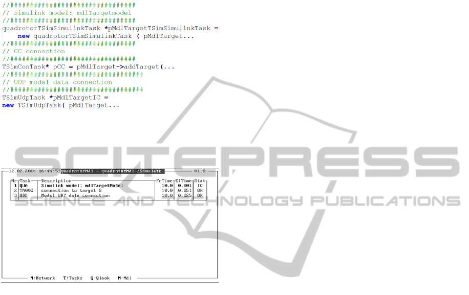
possesses three tasks. The first one is for the model,
the second one is for the Control Center and the last
one is for UDP communication to other simulation
components.
Then the generated source files are cross-
compiled to QNX and the image is deployed to a
QNX target using the open source tool WinSCP.
Figure 9: Console Running quadrotorMdl.
The Model Integration Workflow presented in
this paper ends when the image of the model
application is deployed to the specified target. The
deployment scenarios launch mechanisms and
network settings vary between simulators. Figure 9
presents a snapshot from a QNX console that runs
the deployed model application image.
6 CONCLUSIONS
As in other research flight simulators, model update
is a constant process also in DLR AVES. Flight
systems researchers work for extending and
enhancing their models or their systems. The
presented Model Integration Workflow intends to
make shortened Time-to-Deployment. Furthermore,
with automated code generation and deployment
process, man made errors are avoided.
With this workflow, the flight systems
researchers, that use MBDSD practices, are
supported for easy and fast integration and
deployment of their models. Users of this workflow
can integrate and deploy their models in AVES
within a minimum time.
This workflow is currently operated over the
Matlab command prompt. While it supports update
to deployment process, it lacks in intuitive user
interface for configuration and execution.
Furthermore it has no support for run time
monitoring and debug. Future plans include
developing a graphical user interface and Simulink
blocks for run time monitoring. Thus the users of the
workflow will be able to monitor and debug their
models that run in AVES from Simulink.
REFERENCES
Advani, S., Giovannetti, D. & Blum, M., 2002. Design of
a Hexapod Motion Cueing System fir NASA Ames
Vertical Motion Simulator. In AIAA Modeling and
Simulation Technologies Conference and Exhibit.
Monterey, California, 2002. AIAA.
Allerton, D.J., 1999. The Design of a Real-Time
Engineering Flight Simulator for the Rapid
Prototyping of Avionics Systems and Flight Control
Systems. Transactions of the Institute of Measurement
and Control, pp.51-62.
Allerton, D., 2009. Principles of Flight Simulation. West
Sussex, United Kingdom: John Wiley & Sons, Ltd.
Duda, H., Gerlach, T., Advani, S. & Potter, M., 2013.
Design of the DLR AVES Research Flight Simulator.
In AIAA Modeling and Simulation Technologies (MS)
Conference. Boston, MA, 2013. AIAA.
Estrada, R.G., Sasaki, G. & Dillaber, E., 2013. Best
practices for developing DO-178 compliant software
using Model-Based Design. In AIAA
Infotech@Aerospace (I@A) Conference. Boston, MA,
2013. AIAA.
Fey, I. & Stürmer, I., 2007. Quality Assurance Methods
for Model-based Development: A Survey and
Assessment. In SAE World Congress & Exhibition.
Detroit, Michigan, 2007. SAE.
Fielding, C., 2010. Model-Based Design on Flight Control
Systems. In Mathworks Model-Based Design
Conference. Daventry, UK, 2010. Mathworks, Inc.
Gotschlich, J., Gerlach, T. & Durak, U., 2014. 2Simulate:
A Distributed Real-Time Simulation Framework. In
ASIM STS/GMMS Workshop 2014. Reutlingen,
Germany, 2014. ASIM.
Guido, S. & Thompson, R., 2008. Development of
AUTOSAR Software Components within Model-
Based Design. In Proc. SAE World Congress &
Exhibition. Detroit, MI, 2008. SAE.
Klaes, S., 2000. ATTAS Ground Based System Simulator
-An Update-. In AIAA Modeling and Simulation
Technologies Conference and Exhibit. Denver, CO,
2000. AIAA.
ModelIntegrationWorkflowforKeepingModelsuptoDateinaResearchSimulator
131

Mathworks File Exchange, 2013. PD Control Quadrotor.
[Online] Available at:
http://www.mathworks.com/matlabcentral/fileexchang
e/41149-pd-control-quadrotor-simulink [Accessed 10
February 2014].
Miller, R., 2007. Automatic Code Generation at Nortrop
Grumman. In Mathworks Aerospace and Defence
Conference. Manhattan beach, CA, 2007. Mathworks,
Inc.
Nixon, D.W., 2004. Flight Control Law Development for
the F-35 Jointr Strike Fighter. In The Mathworks
International Aerospace and Defence Conference.
Newton MA, 2004. Mathworks, Inc.
Ruff, R., Stephans, C. & Mahapatra, S., 2012. Applying
Model-Based Design to Large-Scale Systems
Development: Modeling, Simulation, Test, &
Deployment of a Multirotor Vehicle. In AIAA
Modeling and Simulation Technologies Conference.
Minneapolis, Minnesota, 2012. AIAA.
Saager, P., 1990. Real-Time Hardware-in-the-Loop
Simulation for 'ATTAS' and 'ATTHeS' Advanced
Technology Flight Test Vehicles. In AGARD
Guidance and Control Panel, 50th Symposium. Izmir,
Turkey, 1990. NATO.
Samir, B., 2007. Design and Control of Quadrotors with
Application to Autonomous Flying. Ph.D. Thesis.
Lausanne: École Polytechnique Fédérale de Lausanne.
Smith, R.M., 2000. A Description of the Cockpit Motion
Facility and the Research Flight Deck Simulator. In
AIAA Modeling and Simulation Technologies
Conference and Exhibit. Denver, CO, 2000. AIAA.
Stroosma, O., van Paassen, R. & Mulder, M., 2003. Using
the Simona Research Simulator for Human-Machine
Interaction Research. Austin, Texas, 2003. AIAA.
Stürmer, I. & Pohlheim, H., 2012. Model Quality
Assessment in Practice: How to Measure and Assess
the Quality of Software Models During the Embedded
Software Development Process. In Int. Congress of
Embedded Real Time Software and Systems (ERTS
2012). Toulouse, France, 2012. ERTS.
Sullivan, B.T. & Soukup, P.A., 1996. The NASA 747-400
Flight Simulator: A Natonal Reseource fir Aviation
Safety Research. In AIAA Flight Simulation
Technologies Conference. San Diego, CA, 1996.
AIAA.
The MathWorks, Inc., 2007. Matlab Product Help:
Consulting Model Advisor. Help Document. Natick,
MA: The MathWorks, Inc. The MathWorks, Inc.
The Mathworks, Inc., 2014a. Simulink Coder: Generate C
and C++ Code frim Simulink and Stateflow. [Online]
Available at:
http://www.mathworks.com/products/datasheets/pdf/si
mulink-coder.pdf [Accessed 08 April 2014].
The Mathworks, Inc., 2014b. Simulink® Coder™ Target
Language Compiler. Help Document. Natick, MA:
The MathWorks, Inc.
White, M.D. & Padfield, G.D., 2006. The Use of Flight
Simulation for Research and Teaching in Acedemia. In
AIAA Atmospheric Flight Mechanics Conference and
Exhibit. Keystone, CO, 2006. AIAA.
SIMULTECH2014-4thInternationalConferenceonSimulationandModelingMethodologies,Technologiesand
Applications
132
