
Design and Implementation of a Driver Drowsiness Detection System
A Practical Approach
Aleksandar
ˇ
Coli´c, Oge Marques and Borko Furht
Computer & Electrical Engineering and Computer Science Department, Florida Atlantic University,
777 Glades Road, Florida, 33431, U.S.A.
Keywords:
Driver Drowsiness Detection, Fatigue Detection, Drivers Assistance System, Eye-state Recognition, Head
Pose Estimation.
Abstract:
This paper describes the steps involved in designing and implementing a driver drowsiness detection system
based on visual input (driver’s face and head). It combines off-the-shelf software components for face detec-
tion, human skin color detection, and eye state (open vs. closed) classification in a novel way. Preliminary
results show that the system is reliable and tolerant to many real-world constraints.
1 INTRODUCTION
The interest in equipping vehicles with driver drowsi-
ness detection systems has been motivated by alarm-
ing statistics, such as the 2013 World Health Organi-
zation report (World Health Organization, 2013) stat-
ing that: 1.24 million people die on the road ev-
ery year; approximately 6% of all the accidents are
caused by drivers driving in a drowsy state; and most
of the accidents of this type result in fatalities.
Drowsiness (also referred to as sleepiness) can be
defined as “the need to fall asleep”. This process is
a result of normal human biological rhythm and its
sleep-wake cycles. The longer the period of wakeful-
ness, the more pressure builds for sleep and the more
difficult it is to resist it (Akertedt et al., 2002).
There are several different methodologies used
to detect, measure and predict driver drowsiness (or
sleepiness):
• Subjective methods
• Physiological methods
• Vehicle-based methods
• Behavioral methods
• Hybrid methods
For the work described in this paper, we have
adopted a subset of behavioral methods for driver
drowsiness detection. These methods are based on the
detection of behavioral clues, e.g., closing of the eyes,
yawning and nodding of the head. They typically use
a video camera for image acquisition and rely on a
combination of computer vision and machine learn-
ing techniques to detect events of interest, measure
them, and make a decision on whether the driver may
be drowsy or not. If the sequence of captured im-
ages and measured parameters (e.g., pattern of nod-
ding or time lapsed in “closed eye state”) suggest that
the driver is drowsy, an action – such as sounding an
audible alarm – might be warranted.
The remainder of the paper is structured as fol-
lows: Section 2 describes the purposes, context, and
general architecture of our work, Section 3 reports re-
sults from preliminary experiments. Concluding re-
marks are presented in Section 4.
2 OUR WORK
This section describes the requirements, constraints,
basic architecture, and selected algorithms associated
with our driver drowsiness detection system. The
hallmarks of the proposed system are its robustness,
accuracy, and overall simplicity.
2.1 Requirements and Constraints
The driver drowsiness detection system described in
this paper must comply with the following main re-
quirements:
• Algorithmically simple and easy to implement.
We chose to rely on off-the-shelf solutions for
most stages, based on the popularity and success
241
ˇ
Coli
´
c A., Marques O. and Furht B..
Design and Implementation of a Driver Drowsiness Detection System - A Practical Approach.
DOI: 10.5220/0005012302410247
In Proceedings of the 11th International Conference on Signal Processing and Multimedia Applications (SIGMAP-2014), pages 241-247
ISBN: 978-989-758-046-8
Copyright
c
2014 SCITEPRESS (Science and Technology Publications, Lda.)

of the associated algorithms (e.g., Viola-Jones
face detector, Support Vector Machine classifier).
• Easily portable to different platforms. The ap-
plication must run on a mobile device (e.g.,
Android-based smartphone) mounted on the ve-
hicle’s dashboard. Ideally, it should be easily
portable to other (e.g., iOS-based) mobile devices
of comparable size and computational capabili-
ties.
• Computationally non-intensive. Since (near) real-
time performance is required, algorithms must
be optimized to ensure continuous monitoring of
driver’s state without excessive burdening of the
device’s main processor. As a side benefit, battery
consumption is reduced as well.
• Accuracy. One of the main challenges of design-
ing such a system is related to the fact that both
type I and type II errors are highly undesirable,
for different reasons: type I errors (false positives)
will annoy the driver and reduce their willingness
to use the system (due to excessive false alarms),
whereas type II errors (false negatives) can have
literally catastrophic consequences and defeat the
purpose of the entire system.
• Robustness. The system must be tolerant to mod-
est amounts of lighting variations, relative cam-
era motion (e.g. due to poor road conditions),
changes to the driver’s visual appearance (even in
the course of a session, e.g., by wearing/removing
a hat or sunglasses), camera resolution and frame
rates, and different computational capabilities of
the device’s processors.
Some of the anticipated constraints and limitations
faced by the proposed system include:
• Lighting conditions. Frequent and drastic change
in darkness or brightness of a scene (or part of it),
which may happen even during the shortest driv-
ing intervals, have been proven to be a significant
challenge for many computer vision algorithms.
• Camera motion. Poor road conditions as well as
a more aggressive style of driving can introduce
significant amount of vibrations and discomfort
to the driving experience. Those vibrations can
be passed onto the camera and cause distortion in
the images which can significantly skew the re-
sults and decrease the overall performance of the
system.
• Relative positioning of device. The camera must
be positioned within a certain range from the
driver and within a certain viewing angle. Every
computer vision algorithm has a “comfort zone”
in which it performs the best and most reliably.
If that comfort zone is left, performance can be
dropped significantly.
• Hardware and software limitations. Typical mo-
bile devices have one or two processor cores,
reduced working memory and tend to work on
lower clock frequencies, compared to their desk-
top counterparts. The reason for all of this is to
reduce the energy consumptionbut it creates a sig-
nificant obstacle in designing this type of system.
• Driver cooperation. Last, but certainly not least,
all driver drowsiness detection systems assume a
cooperative driver, who is willing to assist in the
setup steps, keep the monitoring system on at all
times, and take proper action when warned by the
system of potential risks due to detected drowsi-
ness.
2.2 System Architecture
Our driver drowsiness detection system consists of
four main stages (Figure 1):
Figure 1: Four stages of Drowsiness Detection System
2.2.1 Detection Stage
This is the initialization stage of the system. Every
time the system is started it needs to be set up and op-
timized for current user and conditions. The key step
in this stage is successful head detection (Figure 2). If
the driver’s head is correctly located we can proceed
to extract the features necessary for setting up the sys-
tem. Setup steps include: (i) extracting driver’s skin
color and using that information to create custom skin
color model and (ii) collecting a set of open/closed
eyes samples, along with driver’s normal head posi-
tion.
To help achieve these goals, user interaction might
be required. The driver might be asked to sit comfort-
ably in its normal driving position so that system can
determine upper and lower thresholds needed for de-
tecting potential nodding. The driver might also be
asked to hold their eyes closed and then open for a
matter of few seconds each time. This is enough to
get the system started. Over time, the system will ex-
pand the dataset of obtained images and will become
more error resistant and overall more robust.
SIGMAP2014-InternationalConferenceonSignalProcessingandMultimediaApplications
242
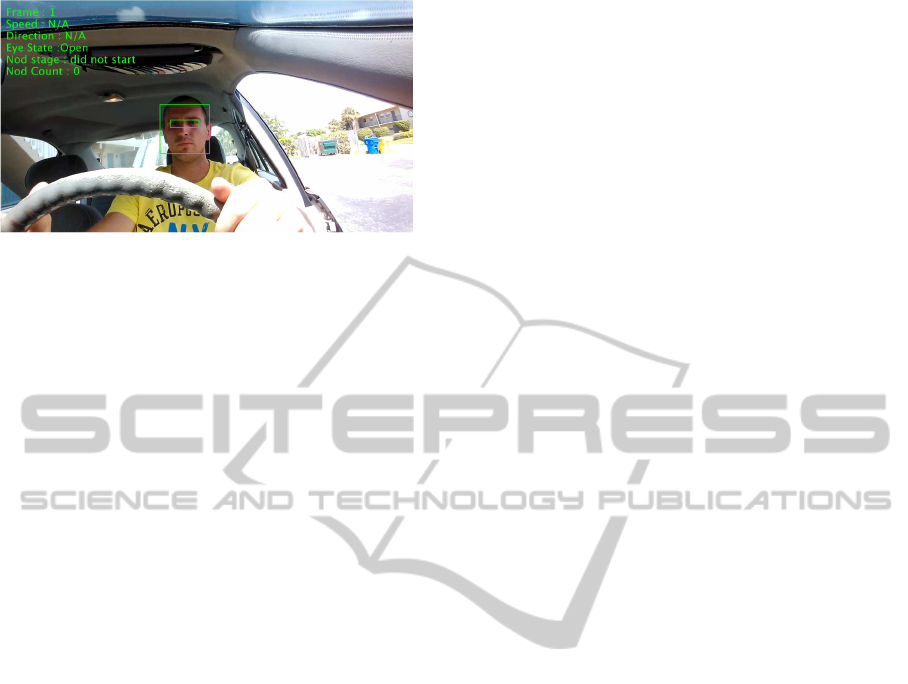
Figure 2: Successful Initial Face and Eyes Detection.
2.2.2 Tracking Stage
Once the driver’s head and eyes are properly located
and all the necessary features are extracted, the sys-
tem enters the regular tracking (monitoring) stage. A
key step in this stage is the continuous monitoring of
the driver’s eyes within a dynamically allocated track-
ing area. More specifically, in order to save some
processing time, the system will determine the size
of the tracking area based on the previous history of
eye movements. For example, if the eyes were mov-
ing horizontally to the left for a number of frames it is
to be expected that that trend with continue in the fol-
lowing frame also. So it is logical to expand the track-
ing area towards the expected direction of the eyes
and shrink the area in other three directions. During
this stage, the system must also determine the state of
the eyes. All these tasks must be carried out in real-
time; depending on the processor’s abilities and cur-
rent load, it might be necessary to occasionally skip a
few frames, without sacrificing algorithmic accuracy.
2.2.3 Warning Stage
If the driver keeps his eyes closed for prolonged pe-
riod of time or starts to nod, alertness has to be raised.
The key step within this stage is close monitoring of
drivers eyes. The system must determine whether the
eyes are still closed, and what is the eyes’ position rel-
ative to previously established thresholds. We cannot
afford to skip frames in this stage. In practice, track-
ing of eyes is performed much in the same way as in
the tracking stage with the addition of the following
processes: calculation of velocity and trajectory of the
eyes and threshold monitoring. These additional com-
putations are required to improve the system’s ability
to determine whether the driver is drowsy or not.
2.2.4 Alert Stage
Once it has been determined that the driver appears to
be in an abnormal driving state, the system has to be
proactive and alert the driver of potential dangers that
can arise. Combination of audio/visual alerts are used
to attract the driver’s attention and raise their alertness
level. Alerting has to be implemented in such a way as
not to cause the opposite effect of intended and startle
the driver into causing an accident.
2.3 Selected Algorithms for Feature
Detection and Image Classification
The proposed system relies on three main features of a
driver: face, eyes and skin. We have chosen the popu-
lar Viola-Jones algorithm for baseline face detection,
due to its wide availability and overall simplicity. We
enhanced the face detection process to make use of
skin color information. Human skin color has unique
features. These features can be best expressed and de-
scribed by breaking given color into its basic chroma
components (red, green, blue), and defining compo-
nents’ ranges. It has been shown that the vast major-
ity of skin color types have their red chroma compo-
nent in a range between 133 and 173, and their blue
chroma component in a range of 77 – 127. One of the
contributions of this work is the adoption of a user-
specific red chroma range. Figure 3 shows differ-
ences between using generalized range and custom,
user specific range.
In the initialization stage of the system, when the
face of the driver is detected, the area containing the
face is used to analyze the specific red chroma range
in which current driver’s skin color falls in. Chroma
values can fall in the range between 0 and 255. His-
togram of red chroma component of the area con-
taining driver’s face is created to give us that specific
range. This specific range is much narrower then the
generalized range. We can extract the upper and lower
boundary from the histogram and use it in the follow-
ing stages of the system. So, when the system tracks
the eyes or face in the following frames, by analyz-
ing the red chroma component histogram we can con-
firm that the tracked object really is pair of eyes or a
driver’s face.
Once our detection algorithm has successfully de-
tected a face and, subsequently, the eyes, it focuses
on determining in what state the eyes are (closed or
open). The proposed system monitors if the driver’s
eyes are being closed for prolonged period of time. If
that is the case, we can conclude that the driver might
be experiencing signs of drowsiness. The classifi-
cation method implemented in our system uses data
from the (most recent) setup stage as training data that
is applied to a 2-class Support Vector Machine (SVM)
classifier whose job is to distinguish the difference be-
tween open and closed eyes.
DesignandImplementationofaDriverDrowsinessDetectionSystem-APracticalApproach
243
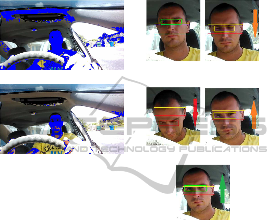
(a) Generalized skin color chroma range
(b) User-specific skin color chroma range
Figure 3: Chroma-based skin detection comparison.
In order to increase the overall robustness of the
system, we have adopted a classification approach
that relies on both head position and eye state. Our
approach is based on the following premises:
• Driver’s head position does not deviate a lot when
fully awake.
• When sleepy, head position changes drastically.
Our system implements a dynamic two-threshold
approach that is simple and effective way of detect-
ing abnormal head behavior of a driver. The upper
threshold is positioned slightly beneath the eyes. As
long as the eyes are located above this threshold sys-
tem considers this to be wide awake, active state of
the driver in which he is looking ahead towards the
road. When the eyes start going vertically down and
cross the upper threshold the system is preparing for
potential nodding. If the head continues to nod for-
ward and the eyes eventually cross the lower thresh-
old we know that driveris certainly not focused on the
road. Human nodding is very specific and consists of
head slowly dropping down followed by rapid recov-
ering right back into original position. Our system
takes this into account. The speed of each stage of
the nodding is measured in order to filter out potential
false positives such as driver nodding in agreement
to something. Figure 4 shows the nodding detection
method.
(a) Eyes above the upper
threshold - nodding did not start
yet
(b) Head tilting down - Eyes be-
neath the upper threshold
(c) Head tilting down - Eyes be-
neath the lower threshold
(d) Head recovering up - eyes
above lower threshold
(e) Head recovering up - eyes
above upper threshold: Nod is
complete
Figure 4: Nodding detection method and its stages.
As long as the eyes are held above the upper
threshold, the system is considered to be in a nor-
mal state. Once the head start tilting vertically down
and crosses the upper threshold, it is considered a be-
ginning of the nodding sequence. From here, if the
head recovers back up, the nodding sequence is can-
celed; but if the head continues down and crosses the
lower threshold, we know that the driver is certainly
not monitoring the road anymore. Also, while mon-
itoring the position of the eyes relative to the thresh-
olds, the system also monitors the state of the eyes.
If at anytime the driver opens his eyes while going
down in his nodding sequence, the sequence is can-
celed. For a “true nod”, the driver has to keep his
eyes closed while moving his head downwards. Once
the lower threshold is crossed, the system can expect
rapid vertical recovery of the driver’s normal driv-
SIGMAP2014-InternationalConferenceonSignalProcessingandMultimediaApplications
244
ing position with potential opening of the eyes while
moving upward. The system also monitors the ve-
locity of the nod since it is essential in distinguishing
a true sleepy nodding from other potentially similar
head movements that are not caused by nodding.
3 PRELIMINARY EXPERIMENTS
In order to fulfill all of the challenging prerequisites
we have to test out limitations of our chosen off-the-
shelf components. Some of our preliminary tests were
devised to help us out with that. We started by setting
our work environment in MATLAB. For the purposes
of testing, we simplified our dynamic solution to its
core, into a horizontal, linear solution that can per-
form basic face/eye detection as well as simple classi-
fication task of determining eye state. The goal of the
devised set of experiments is to test the basic perfor-
mance in various ways.
From the very beginning we decided to use Viola-
Jones algorithm, Haar-like feature based face/eyes de-
tection algorithm available in MATLAB (Viola and
Jones, 2001). It is known for being stable and compu-
tationally non-intensive algorithm. Haar-like feature
can be described as a set of two or more adjacent rect-
angular regions organized in a specific way in a given
detection window. This algorithm proves to be com-
pute non-intensive since it’s core operation is simple
summing up of the pixel intensities in a given regions,
followed by calculation of differences between them.
That difference is then used to categorize subsections
of an image to be face/eyes or not.
Also, for differentiating between open and closed
eyes we decided to go with a proven two-class Sup-
port Vector Machine (SVM) classifier (Cortes and
Vapnik, 1995). SVM is a non-probabilistic binary lin-
ear classifier. It takes a set of input data and predicts,
for each given input, which of two possible classes
forms the output. This is perfect since our basic prob-
lem can be defined as two class problem: open eyes
vs. closed eyes.
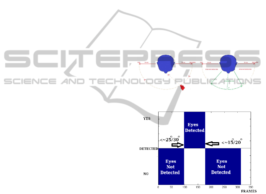
3.1 Camera Rotation Test
The aim of this test is to find out how does move-
ment of the camera and change in the viewing angle
relative to the driver influences the performance of
used face/eye detection algorithm as well as the con-
sistency of its detection. The experiment was setup in
following manner: the driver is sitting inside the car,
looking towards the road; the camera, approximately
50 centimeters away from the driver’s head, will make
a semi-circle around the driver’s head, keeping the
same distance throughout; the camera starts pointed
at driver’s left profile and ends pointing at driver’s
right profile. The driver’s head stays stationary, only
the camera moves around it while keeping constant
distance from it. Video used for testing contains 310
frames of driver’s head from various angles. Figure 5
shows the process and the results. We can deduct that
the detection algorithm performs consistently. If we
define an angle of 0 degrees to be when the camera
is directly facing the driver, we can conclude that the
range in which it was reliably detecting drivers eyes
falls approximately within 25 degree viewing angle
in both direction from a driver. This result is very
encouraging since this means that we can position the
camera of the system conveniently on car’s dashboard
(usually has available slot for attaching devices such
as phones etc.) which is within driver’s reach.
(a) Test setup (b) Angle range results
(c) Consistency results
Figure 5: Camera rotating: angle change limitations.
3.2 Head Rotation Test
In this test the camera stays directly facing the driver
while the driver rotates his head to the right, returns
to the starting position and then rotates the head to the
left and back to center again. We are again looking to
see what is the angle of breaking for our head/eye de-
tection algorithm and what is its consistency across
the frames. Figure 6 is showing the tests setup and re-
sults. Difference in detection angles is much smaller
than in previous test, only around 5 degrees. It seems
that the algorithm is consistently and reliably detect-
DesignandImplementationofaDriverDrowsinessDetectionSystem-APracticalApproach
245
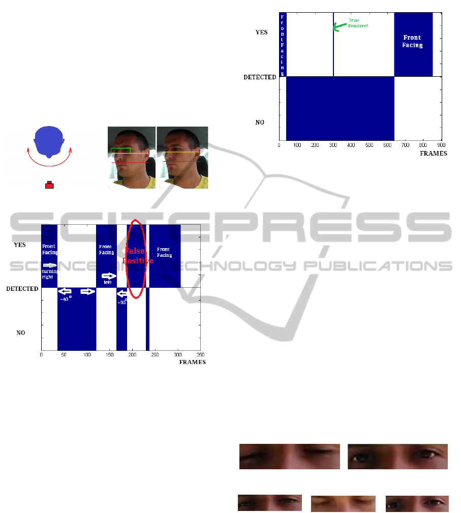
ing drivers eyes as long as the driver is facing towards
the camera and his gaze does not deviatemore then 35
degrees in both directions from the front facing posi-
tion. Even though the difference in detection angles is
much smaller, there is an obvious false positive pro-
duced when drivers head turns almost 90 degrees to
the left. Though one eye is visible the other eye is
completely occluded. Background influenced the al-
gorithm into wrong conclusion.
(a) Test setup (b) Angle range results
(c) Consistency results
Figure 6: Head rotating: angle change limitations.
3.3 Real-world Test
For pure test of consistency of the detection algo-
rithm we recorded an approximately 900 frame video
sequence of a driver behaving naturally behind the
wheel of the car. He is moving around, adjusting his
seat, mirror, turning to face the passengers. We want
to see if there are false positives and in what volume
and how reliable or basis detection algorithm really
is. Figure 7 is showing quite good consistency: there
are no sudden changes except with one spike for the
duration of one frame. This spike actually is a true
positive.
3.4 Open vs. Closed Eyes Test
To test the behavior of our chosen classification al-
gorithm we decided to go with the simple solution of
using gray-scaled and cropped image regions contain-
ing eyes and to feed that set of pixels as an input to the
Figure 7: Real-World test results.
SVM classification algorithm. A special video con-
taining 571 frames of a driver sitting in a drivers posi-
tion is used. Driver is moving minimally. Every frame
is manually marked as containing open or closed eyes.
Open and closed eye samples are roughly the same in
number, 304 containing open eyes and 267 contain-
ing closed eyes. 70 % of randomly selected samples
were used to train the SVM model on which the re-
maining 30% of the samples were tested. Using avail-
able SVM MATLAB version, our preliminary results
showed 96 % success rate. We are acknowledging
the fact that the sample size is very small and that we
only had samples relating to one subject so instead
on focusing on high accuracy rate we concluded that
building a system in which an SVM eye model is user
specific is encouragingly good idea. It can simplify
significantly our system as well as provide a dose of
robustness and reliability to it. Such an eye model can
always be upgraded, thus increase its quality, through
frequent use of the system. Some of the classification
results are shown on Figure 8.
(a) Closed (b) Open
(c) Called closed (d) Called open (e) Called closed
Figure 8: Support Vector Machine result examples: (a) &
(b) correct; (c), (d) & (e) incorrect.
4 CONCLUDING REMARKS
In this paper, we havedescribed the process of design-
ing and implementing a driver drowsiness detection
system by combining some off-the-shelf algorithms
SIGMAP2014-InternationalConferenceonSignalProcessingandMultimediaApplications
246

with some of the novel approaches in a clever man-
ner. The system is dynamic, it can update and mod-
ify its components like current drivers eye model and
skin model throughout its life cycle. Constantly up-
grading baseline models used can increase the over-
all resilience towards errors. Moreover, the system
is user specific. All the feature models created are
solely based on the current users features instead of
using generalized parameters. Such an approach sim-
plifies the system while providing solid performance.
Each of the algorithms is performing solidly by itself.
But they do have their limitations. To increase the
reliability and accuracy of the system, both baseline
detection/tracking algorithm and eye-state classifica-
tion algorithm are complimented with simple, but ef-
ficient, custom algorithms.
REFERENCES
Akertedt, T., Fredlung, P., Gillberg, M., and Jansson, B.
(2002). A prospective study of fatal occupational ac-
cidents – relationship to sleeping difficulties and occu-
pational factors. Journal of Sleep Research, 11(1):69–
71.
Cortes, C. and Vapnik, V. (1995). Support-vector networks.
Machine Learning, 20(3):273–297.
Viola, P. and Jones, M. (2001). Robust real-time object de-
tection. In International Journal of Computer Vision.
World Health Organization (2013). Global Status Report
on Road Safety 2013: Supporting a Decade of Action
: Summary. World Health Organization.
DesignandImplementationofaDriverDrowsinessDetectionSystem-APracticalApproach
247
