
Fuzzy Controller based on PLC S7-1200
Application to a Servomotor
Isaías González Pérez, A. José Calderón Godoy and Manuel Calderón Godoy
Industrial Engineering School, University of Extremadura, Avenida de Elvas, Badajoz, Spain
Keywords: Fuzzy Control, Process Automation, PLC, Servomotor.
Abstract: This paper presents the design and validation of a fuzzy logic controller implemented with an industrial
programmable logic controller (PLC). The chosen device belongs to the S7-1200 series of Siemens, whereas
the code has been developed in Ladder Diagram language using the software TIA Portal. The fuzzy
controller is of Mamdani type and is applied to control the speed of a servomotor. A comparison with a
Simulink/Matlab fuzzy controller is done to validate the developed software module and to show the
feasibility of the PLC to manage this kind of control algorithm.
1 INTRODUCTION
Fuzzy logic emerged from studies of Lofti A. Zadeh
in 1965. It is a mathematical formalism to represent
the human reasoning so it is very useful in Expert
Systems and Artificial Intelligence applications.
Fuzzy based control or fuzzy control began to
develop at 70’s. Nowadays it is applied in several
processes with demonstrated effectiveness and great
interest from the scientific and technologic
community.
The main advantages of fuzzy logic for process
control are fast decision capability, applicability to
nonlinear systems, and intuitive definition of the
controller behaviour. Furthermore, there is no need
of either historical data or mathematical models like
other intelligent controllers such as neural networks
or genetic algorithms.
PLC are electronic devices to control sequential
processes. Their main features are high reliability
and robustness. They are widely applied in industrial
processes, but are used in other fields such as home
and building automation, renewable energies
systems, etc.
It is evident the interest of combining and
integrating an advanced control method, like fuzzy
logic, with traditional automation devices, PLC. This
way, PLC can be applied in systems where it is
difficult to obtain accurate models or with
nonlinearities, delays, etc.
The calculation power of modern PLC allows
implementing advanced control strategies in their
programs. The implementation of fuzzy controllers
in PLC makes them useful for many applications in
industrial environment.
Lots of PLC manufacturers offer additional
software packages or modules to program fuzzy
controllers, FLC (Fuzzy Logic Controller). The
disadvantages are the consequent cost increment
and, mainly, an absolute lack of flexibility to modify
their codification.
On the other hand, due to the growing interest
and application to process control, fuzzy control has
a specific section in the open international standard
IEC 1131, which is referred to PLC standardization.
In 1997, the part IEC 1131-7 defined the Fuzzy
Control Language, FCL, i.e., a group of functions to
program applications of fuzzy control. In addition,
several research works study advanced fuzzy
methods such as fuzzy modelling and control
(Piegat, 2001; Zhang and Liu, 2006), and neuro-
fuzzy controllers (Joelianto, 2013).
Scientific literature about controllers based on
fuzzy logic implemented by means of PLC is scarce.
In the case of Siemens s7-1200 model, no works
have been found in the studied bibliography. Despite
that scarcity, there are some examples which are
exposed from this point.
In (Ruan and Van der Wal, 1998), a fuzzy
controller is developed in an Omron PLC (Sysmac
C200HS) to control the output power of a nuclear
reactor. The programming of the FLC is performed
using specific software and module. In (Li and Tso,
1999) a fuzzy controller with an Omron PLC is
156
González Pérez I., José Calderón Godoy A. and Calderón Godoy M..
Fuzzy Controller based on PLC S7-1200 - Application to a Servomotor.
DOI: 10.5220/0005013601560163
In Proceedings of the 11th International Conference on Informatics in Control, Automation and Robotics (ICINCO-2014), pages 156-163
ISBN: 978-989-758-039-0
Copyright
c
2014 SCITEPRESS (Science and Technology Publications, Lda.)

applied to a thermal process. The limitation in the
processing capacity of the PLC led to the authors to
run a program in a PC to solve the knowledge base.
Karasakal et al. (Karasakal, 2005) use a Siemens
PLC s7-200 to implement a fuzzy PID controller
with auto tuning and compare it with classical PID.
Bogdan et al. (Bogdan, 2007) implement a Self-
Learning Fuzzy Logic Controller, SLFLC, for
Simatic PLC which is applied to control the position
of a servo motor. Song et al. (Song, 2007) develop a
fuzzy controller based on a Siemens PLC s7-200 to
automate the processing of egg powder. Sun et al.
(2009) apply a fuzzy controller with a Siemens PLC
s7-300 to a sewage disposal system of a chemical
plant. The authors indicate the high cost of modules
for fuzzy logic of the manufacturer. They allege that
the developed controller is accurate and flexible due
to the ability to adapt to user demands.
Aydogmus (Aydogmus, 2009) present a fuzzy
controller implemented with a Siemens PLC s7-200
to control a tank level. This researcher describes his
proposal as a low cost solution because of the fact
that it has been developed without using fuzzy logic
software packages. In (Saad and Arrofiq, 2012) a
method to develop fuzzy-PID controllers in PLC for
PWM-driven induction motors is presented. In
(Cingolani and Alcalá, 2012) an open code library
based on Java, iFuzzyLogic, to design and
implement fuzzy controllers following the standard
IEC 61131-7 for Fuzzy Control Language is
exposed. Furthermore, a review of 25 software
packages dedicated to develop fuzzy controllers is
performed, highlighting the interest received by this
control technique.
On the other hand, Bosque et al. (Bosque, 2014)
assert that the programming flexibility and the cost
of PLC contribute to the implementation of fuzzy
control in industrial environments.
The main objective of this work is the design and
validation of a software module to implement fuzzy
logic controllers with a PLC. The case of speed
control for a servomotor is considered for this
purpose.
The rest of the paper is organized as follows.
Section 2 describes the main features of the PLC, the
servomotor and the software involved. In section 3
the programming of the module for fuzzy control
with the PLC s7-1200 is shown. In section 4 a fuzzy
controller designed for speed control of the
servomotor is described. The experimental results
are shown in section 5. Finally, conclusions and
further works are outlined.
2 SYSTEM DESCRIPTION
The module for fuzzy control has been developed
for the PLC s7-1200 of Siemens. TIA Portal V11
(Totally Integrated Automation Portal) of Siemens is
the software used to program and configure the PLC.
WinCC flexible 2008 Runtime is used to design a
Human-Machine Interface, HMI, based on PC to
monitor the process under control and to store the
data for further analysis.
The CPU model of the PLC is the 1214C which
incorporates Ethernet/PROFINET interface and 2
analogue inputs. In addition, an added Signal Board,
SB 1232 AQ1, module provides an analogue output
that will be used to apply the control signal to the
servomotor.
The servomotor corresponds to the Servo
Fundamentals Trainer (33-001) by Feedback (Figure
1). On the one hand, it comprises a mechanical unit
(33-100) which contains the DC motor, an analogue
tachogenerator, encoders, potentiometers, magnetic
brake and other supporting electronics. On the other
hand, an analogue unit (33-110) and a power supply
(01-100) provide the power supplies and signals.
Connection between both units is by way of a ribbon
cable for signal transmission.
a)
Figure 1: Servo Fundamentals Trainer (33-001).
This equipment allows open and closed loop
speed and position control. It can be linked with a
PC through USB connection. In our case, these
possibilities are not used because both the control
and data acquisition are carried out by the PLC.
2.1 System Integration
The PLC is responsible of operations such as sensors
data acquisition, fuzzy control algorithm execution
and driving of actuators according to the control
signal generated. Furthermore, the PLC
communicates with the system for monitoring
FuzzyControllerbasedonPLCS7-1200-ApplicationtoaServomotor
157
(HMI) through the Ethernet network where both
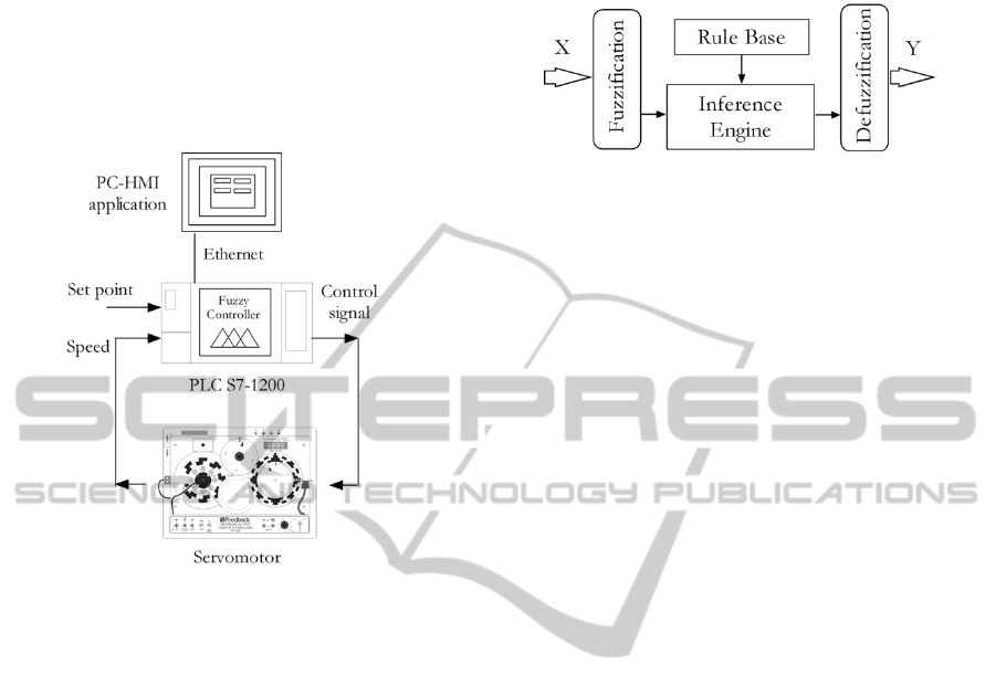
devices are integrated. Figure 2 illustrates the
scheme of connections between the components of
the system. The HMI application runs in the
computer connected to the PLC via Ethernet by
using the PROFINET interface. This application
accesses to data blocks in the PLC memory to be
stored and displayed.
Figure 2: Connections between PLC, HMI and Servo.
3 FUZZY CONTROL MODULE
Fuzzy logic allows using the common language to
describe problems; this is, to process inaccurate and
qualitative information in terms of fuzzy sets.
Because of this, fuzzy logic is better than classical
logic to represent the human knowledge and
reasoning. Fuzzy control consists on leading the
process output to a desired value with control
actions calculated according to a fuzzy description
of such process. Fuzzy control is the main field of
application of fuzzy logic and uses the experience in
manual operation over a plant to design the control
system.
The general structure of a fuzzy controller is
depicted in the block diagram of Figure 3. The
fuzzification of each natural value of the inputs
consists in determining the degree of membership to
each defined fuzzy set. The inference engine uses
the fuzzy rules to process the input information and
to generate the controller output. The defuzzification
process converts the result of the fuzzy rules into a
numeric or crisp value, non-fuzzy, which acts as the
controller output signal.
In the module here presented each one of those
parts has been solved by means of a subroutine,
called function or FC, in the PLC.
Figure 3: Block diagram of a fuzzy controller.
Mamdani type fuzzy controllers can be
implemented with the developed module. This kind
is more intuitive and adapted to the human language
with respect to Sugeno type.
Ladder Diagram language has been used to
develop the required code to perform the operations
of the fuzzy algorithm.
The maximum number of variables is 6, for each
one of them can be defined up to 5 subsets. Each
subset is determined by means of 4 points. The
available fuzzy logic operations are AND and OR.
The first one can be applied by the Product or the
Minimum procedure, whereas the OR operation is
solved by the Maximum method. The rule base can
be composed of up to 9 rules. The implication
method is Min. The aggregation method is Max.
Only one output variable is considered, so the
controllers developed are of MISO (Multiple Inputs
Single Output) type.
The design of the controller and its parameters
must be performed in a stage before the
configuration of the PLC. Hence, the developed
module does not serve to design the fuzzy controller,
but the implementation of such controller. Once the
engineer or designer has established the controller
parameters (I/O, rules, etc.); these ones will be
programmed in the PLC via the TIA Portal software.
3.1 Fuzzy Module Structure
The fuzzy module has been developed to be versatile
and user friendly. Furthermore, the use of Ladder
diagram with a modular design provides a flexible
very useful for future improvements structure.
The user has to specify and configure in the PLC
the following parameters of the fuzzy controller:
─ Input variables: number, points defining fuzzy
subsets.
─ Output variable: points defining fuzzy subsets.
─ Rules: number, premises and conclusions.
─ Fuzzy logic operation: AND or OR, with
Minimum or Product options for AND.
In order to optimize the CPU performance
ICINCO2014-11thInternationalConferenceonInformaticsinControl,AutomationandRobotics
158
according to the available resources, several
functions, FC, have been included. Each FC is
designed to carry out a determined processing of
information. These blocks have input and output
data, but do not require associated data block which
would occupy memory and would slow down the
calculations. The required data (variables, points of
membership functions, etc.) are stored in Data
Blocks, DB, which are available for the FCs.
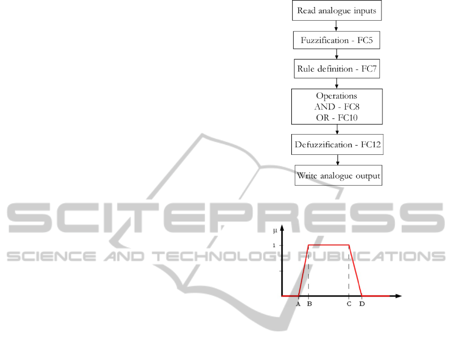
Figure 4 shows the flowchart of the module for
fuzzy control in the s7-1200 PLC. From the main
program, OB1, the FCs that implement the different
parts of the fuzzy control algorithm are called
sequentially. Reading of input data and writing of
the output signal are made directly in the OB1. The
control signal is applied to the servomotor by means
of the voltage analogue output obtained through the
Signal Board.
3.1.1 Fuzzification
The Trapezoidal function acts as basis to define the
membership functions, so there are 5 available
functions: Trapezoidal, S, Z, Triangular and
Singleton. In the case of functions S and Z type, due
to their configuration as particular cases of the
Trapezoidal one, they are not soft, simplifying this
way their codification.
The maximum number of subsets is 5 and the
linguistic labels are S1, S2, S3, S4 and S5 for all the
variables. To define these functions the user has to
introduce the values of 4 points signalled as A, B, C
and D in Figure 5, for all subsets of each variable. It
is not required to specify the range of input variables
due to the fact that it is implicitly expressed with the
points that define the subsets as said before.
The calculation of membership degrees begins
with a comparison between the actual value of the
variable and the points that define the functions.
If the input is located in an interval which
corresponds to a membership degree of 0 or 1, such
value is directly assigned (no more operation is
needed). In another case, the equation that defines
the straight line is determined and used to calculate
the membership degree. Figure 6 shows the
described sequence as flow diagram, where MD
means membership degree.
3.1.2 Rules
A maximum of 9 rules can be formulated, all of
them of Mamdani type. This number of rules has
been considered adequate for the application here
exposed, but a higher number can be programmed.
Figure 4: Flowchart of the module for fuzzy control in
PLC.
Figure 5: Points required to define the Trapezoidal
membership function.
Each one of these rules can incorporate all of the
input variables that have been defined. In addition,
each rule has a weight factor associated, which can
vary between 0 and 1.
A FC, called “Rule definition”, carries out the
selection of the fuzzy subsets of the inputs according
to the user specifications to constitute the
antecedents or premises. To this aim, the user
indicates if an input must be included in each rule
using a 1 bit memory position.
Later, for each variable an integer number
defines the subset associated to such variable. Based
on this information, a multiplexer selects the
membership degree that corresponds to the defined
subset, generating the premises. The same procedure
is followed for the subsets associated to the output
variable to define the consequents. Figure 7
illustrates the multiplexation process for the rule 1,
were, µS1(V1) is the membership degree to the first
subset of the first variable.
3.1.3 Operations
The fuzzy logic operations can be chosen between
the intersection (AND) and the union (OR).
FuzzyControllerbasedonPLCS7-1200-ApplicationtoaServomotor
159
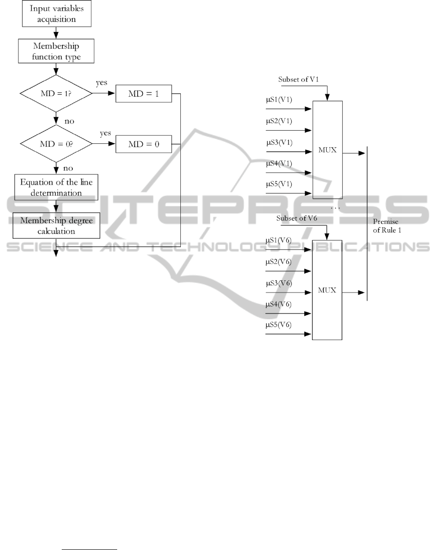
Figure 6: Flowchart for fuzzification of input variables.
Furthermore, there are two options to select the
method for the AND operation: Minimum and
Product. In the event of OR operation, the applied
method is Maximum. These selections are defined
using a bit position.
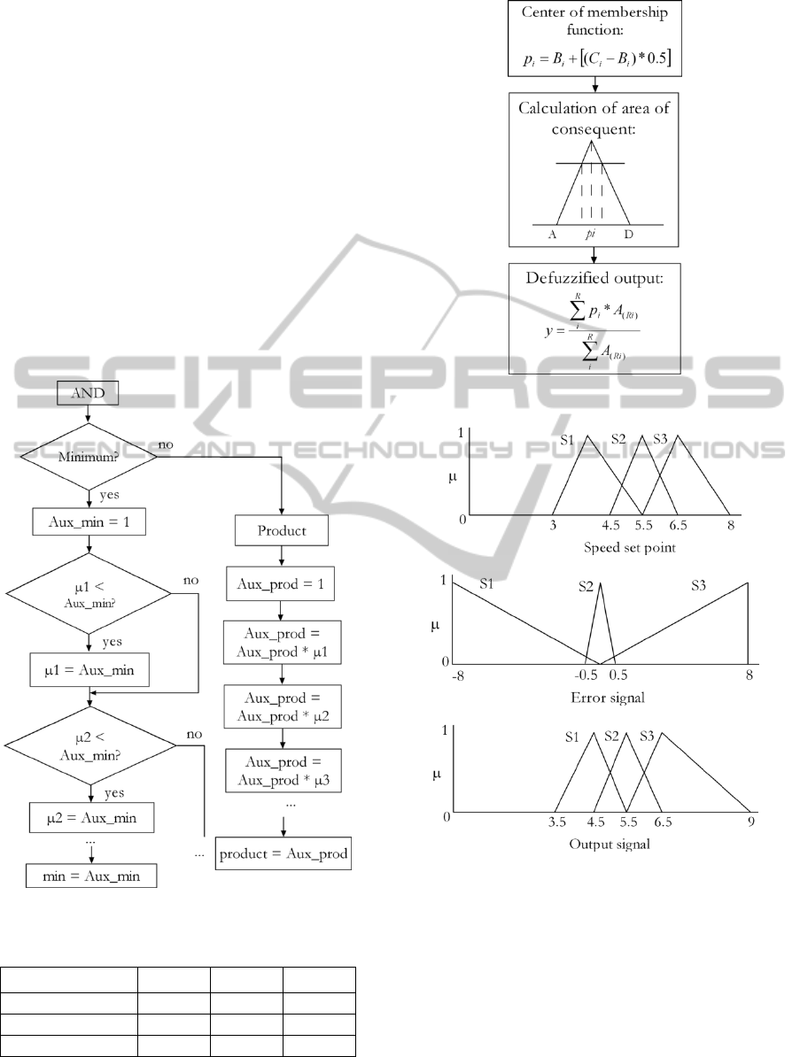
The procedures for performing these operations
are briefly described. In the case of AND operation
using minimum criterion, successive comparisons
between the membership degrees are performed
until obtaining the minimum value. When the
product method is chosen, the membership degrees
are multiplied (Figure 8). For the OR operation, the
maximum criterion is performed by means of
successive comparisons until reaching the maximum
membership degree.
3.1.4 Defuzzification
The programmed defuzzification method is the
centroid, also called center of gravity.
The defuzzified output signal is obtained
applying the following equation:
∑
∗
∑
(1)
where p
i
is the centre of the membership function of
the consequent of each rule, and A
(Ri)
is the surface
of such subset truncated by the membership degree
result of the premises of such rule. This last
procedure corresponds to the implication method
Minimum. This area is calculated as the surface of a
trapezoid, resulting very simple from the point of
view of computational resources. Figure 9 shows the
flow diagram of the defuzzification process.
Figure 7: Multiplexation for premises configuration.
4 FUZZY CONTROLLER FOR
SERVO SPEED CONTROL
The servomotor is a well-known first order system
so its speed control is considered an illustrative
process to test and validate the developed fuzzy
module.
It is necessary to clarify that the aim of this work
is not to design or optimize a controller for the
servomotor, but test and validate the FLC.
The membership functions and rules were
adjusted during trials with different input signals.
Simulink and Fuzzy Logic Toolbox of Matlab were
used at this stage. Once the FLC was tuned, it was
coded in the PLC program language.
The input signals are the voltages of reference or
set point speed and the error of the actual speed. The
output signal is generated by the FLC for the
servomotor to reach the desired speed.
The structure of the FLC has been made as
ICINCO2014-11thInternationalConferenceonInformaticsinControl,AutomationandRobotics
160
simple as possible. The fuzzy controller is of
Mamdani type, the And method is Min, the
implication operator is Min, the Aggregation is Max
and the defuzzification strategy is the Centroid of
area. Triangular membership functions are adequate
for this application, so they have been used for input
and output variables. Membership functions for
speed set point, error signal and output variable are
presented in Figure 10. These variables have been
defined by means of 3 fuzzy subsets despite the fact
that the module is able to manage 5 subsets.
Input ranges goes from 0 to 8 V for the speed set
point. Although the interval where the servomotor
behaviour is lineal goes from 3 to 8 V. In the case of
the error signal, the input range is -8 to 8 V. The
range of output signal is 3.5 to 9 V. The fuzzy rules
that define the FLC behaviour are represented by
means of a matrix as can be seen in Table 1.
Figure 8: Flowchart of AND operation.
Table 1: Rules of the FLC.
Set point/Error
S1 S2 S3
S1 S1 S1 S2
S2 S1 S2 S3
S3 S2 S3 S3
Figure 9: Flowchart of defuzzification process.
a)
b)
c)
Figure 10: Membership functions for: a) Speed set point,
b) Error signal, c) Output signal.
5 EXPERIMENTAL RESULTS
With the aim of evaluating fuzzy module behaviour,
a comparison with the FLC designed using the
Fuzzy Logic Toolbox of Matlab is carried out. This
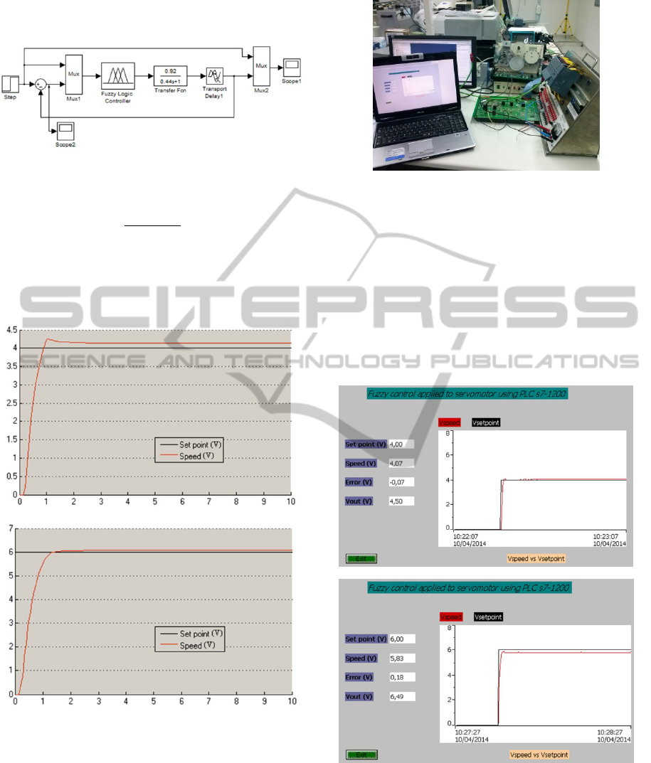
way, a set of simulations has been developed in
Simulink using the scheme shown in Figure 11. The
FuzzyControllerbasedonPLCS7-1200-ApplicationtoaServomotor
161
transfer function for the servomotor (Equation 2)
was experimentally obtained.
Figure 11: Simulink scheme to simulate a fuzzy controller
applied to the servomotor.
FDT
0.92
0.44s1
(2)
Figure 12 shows the servomotor response for
three steps with amplitudes of 4 and 6 V. In this
figure the set point speed is in black, while the
servomotor speed corresponds to the red line.
a)
b)
Figure 12: Servomotor speed response simulation applying
step input with amplitude: a) 4 V, b) 6 V.
Once the proposed FLC for controlling the
servomotor has been simulated, the next step
consists in testing the fuzzy module under real
conditions. To this aim, the FLC implemented in the
PLC has been applied to the servomotor for several
trials. Figure 13 contains a photograph of the whole
system connected in the laboratory.
Figure 13: Components of the system in the laboratory.
The HMI allows visualizing in real-time the
numerical and graphical evolution of the servomotor
speed as can be seen in Figure 14. The
corresponding colours to the variables are the same
of Figure 12. The step amplitudes are the same as
shown for the simulations, 4, 5.5 and 6 V.
Table 2 contains the steady-state error expressed
as a percentage for the most representative trials in
both of the situations, the simulation and the PLC
implementation.
a)
b)
Figure 14: Screens of the HMI showing the servomotor
speed response to step input with amplitude: a) 4 V, b) 6
V.
As can be appreciated, the output signal
generated by the FLC leads the servo speed to the
desired value with an acceptable steady-state error
ICINCO2014-11thInternationalConferenceonInformaticsinControl,AutomationandRobotics
162

and high stability. In both of the cases the errors
reached are small and the difference between them is
slight. The main cause of such difference is the
higher resolution and computational resources of
Simulink.
Table 2: Steady-state error comparison.
Vsetpoint
Steady-state error (%)
Simulink PLC
4 -3.5 -1.7
5 4.2 6.2
5.5 4.7 4.7
6 -1.1 2.8
On the view of these results we can conclude
two facts. On the one hand, it has been demonstrated
the ability of the developed controller to adjust the
servomotor speed to the required set point. On the
other hand, these data validate the module developed
to implement fuzzy controllers in the PLC s7-1200.
6 CONCLUSIONS
A software module to implement fuzzy controllers in
a Siemens PLC s7-1200 has been presented. A
servomotor has been used as test platform to validate
the developed PLC-Fuzzy Controller.
The results under real operating conditions
constitute a proof-of-concept of the feasibility of the
proposed system.
A positive feature of the developed work is the
utilization of a PLC of recent market release and,
hence, progressive introduction in industrial plants
and research teams. This device belongs to Siemens
low-end performance range, providing automation
solutions with minor costs.
This work has contributed to a better
understanding of the abilities and procedures to
implement fuzzy controllers in PLC.
Future works focus on the application of the
controller to more complex systems such as a
hydrogen generator integrated in a hybrid renewable
energy system. Also, its integration with software
applications using OPC protocol and the
programming of more options such as fuzzy PID
structure are under study.
ACKNOWLEDGEMENTS
Authors are grateful to the University of
Extremadura and to the Gobierno de Extremadura
for their financial support by grant GR10157 and
FEDER (Fondo Europeo de Desarrollo Regional:
Una Manera de Hacer Europa).
REFERENCES
Aydogmus, Z., 2009. Implementation of a fuzzy-based
level control using SCADA. Expert Systems with
Applications, vol. 36, pp. 6593-6597.
Bogdan, S., Kovacic, Z., Krapinec, D., 2007. Sensitivity-
based self-learning fuzzy logic controller as a PLC
super block. 15th IEEE Mediterranean Conference on
Control and Automation, Athens, Greece.
Bosque, G., del Campo, I., Echanobe, J., 2014. Fuzzy
systems, neural networks and neuro-fuzzy systems: A
vision on their hardware implementation and platforms
over two decades. Engineering Applications of
Artificial Intelligence, vol. 32, pp. 283-331.
Cingolani, P., Alcalá, J., 2012. jFuzzyLogic: a robust and
flexible fuzzy-logic inference system language
implementation. IEEE World Congress on
Computational Intelligence, Brisbane, Australia.
Joelianto, E., Anura, D. C., Priyanto, M., 2013. ANFIS –
hybrid reference control for improving transient
response of controlled systems using PID controller.
International Journal of Artificial Intelligence, vol. 10,
pp. 88-111.
Karasakal, O., Yesil, E., Guzelkaya, M., Eksin, I., 2005.
Implementation of a new self-tuning fuzzy PID
controller on PLC. Turkish Journal of Electrical
Engineering & Computer Sciences 13, no. 2, 277-286.
Li, H. X., Tso, S. K., 1999. A fuzzy PLC with gain-
scheduling control resolution for a thermal process – a
case study. Control Engineering Practice, vol. 7, pp.
523-529.
Piegat, A., 2001. Fuzzy Modeling and Control (Studies in
Fuzziness and Soft Computing Series). Physica Verlag,
A Springer Verlag Company, Heidelberg, Germany.
Ruan, D., Van der Wal, A.J., 1998. Controlling the power
output of a nuclear reactor with fuzzy logic.
Information Sciences, vol. 110, pp. 151-177.
Saad, N., Arrofiq, M., 2012. A PLC-based modified-fuzzy
controller for PW-driven induction motor drive with
constant V/Hz ratio control. Robotics and Computer-
Integrated Manufacturing, vol. 28, pp. 95-112.
Song, Y., Bi, Z., Liu, K., 2007. The PLC system of egg
powder treatment based on fuzzy control algorithm.
4th IEEE International Conference on Fuzzy Systems
and Knowledge Discovery, Haikou, China.
Zhang, H., Liu, D., 2006. Fuzzy Modeling and Fuzzy
Control (Control Engineering). Birkhäuser, Boston.
FuzzyControllerbasedonPLCS7-1200-ApplicationtoaServomotor
163
