
Modeling and H
∞
Composite Control of the Coupled Hysteretic
Dynamics in Piezoelectric Micro-displacement Systems
Liang Tang
1
, Lei Liu
2
and Xin Guan
1
1
Beijing Institute of Control Engineering, National Laboratory of Space Intelligent Control, 100080, Beijing, China
2
State Key Laboratory of Structural Analysis for Industrial Equipment, School of Aeronautics and Astronautics,
Dalian University of Technology, Dalian 116024, China
Keywords:
Hysteretic Dynamics, Piezoelectric Actuator, Broadband Control, Jitter Control.
Abstract:
This paper investigates the modeling and H
∞
composite control of the coupled hysteretic dynamics in a piezo-
electric micro-displacement system (PMS). First, the coupled multi-field hysteretic dynamics with physical
meanings is presented for PMS. Next, the composite control analysis of the hysteretic dynamics is proposed.
Then, a H
∞
synthesis controller is designed by using the simplified hysteretic dynamics. To enhance the H
∞
performance, the inversion-based feedforward compensation is augmented. The proposed H
∞
feedback con-
trol and the inversion-based feedforward can be designed separately. Finally, the experimental studies are
provided to demonstrate the proposed H
∞
composite control approach.
1 INTRODUCTION
Piezoelectric micro-displacement systems (PMSs) are
widely investigated to suppress jitters and micro vi-
brations produced by reaction flywheels, control mo-
mentum gyroscopes, Stirling coolers and step motors
of precision spacecrafts, such as inter-satellite laser
communication, space telescope and missile warn-
ing satellite with staring camera (Kamesha and Ghos-
alb, 2010; Maillarda and LeLettya, 2009; Nagashima
and Agrawal, 2014; Dewella and Blaurockb, 2005;
Maillarda and LeLettya, 2009; Laneand and Lacy,
2008; Neat and Goullioud, 1998; McMickell and
Hansen, 2007). For instance, piezoelectric fast steer-
ing mirrors are employed to suppress jitters of line-of-
sight(LOS) in inter-satellite laser communication and
space telescopes. To reject jitters and micro vibra-
tions, broadband control of PMS is increasingly ap-
pealing, but most of the operating bandwidth of PMS
is still insufficient.
To enhance the bandwidth and performance of
PMS, various controllers were designed (Devasia and
Moheimani, 2007). If tracking signals are at low fre-
quencies, proportional-intergral-derivative (PID) and
notch filter are adequate (Fleming, 2010). As the ref-
erence signal frequency increases, model based con-
troller are alternativelydesigned, such as H
∞
feedback
control (Wu and Zou, 2009), inversion-based feed-
forward control (Liu and Lee, 2013b; Tan and Ang,
2009; Liu and Lee, 2013a). Accurate modeling over
a broad frequency range is necessary to enhance the
performance of model-based control.
At broadband frequencies, the hysteretic dynam-
ics of PMS has multi-field effects. It is required to
model the coupled hysteresis, creep, electric and vi-
bration dynamics. Hysteresis is a strongly nonlinear
element with global memory (Brokate and Sprekels,
1996). Preisach model is typically to describe the
static hysteresis (Mayergozy, 2003). Creep is slow
dynamics and can be represented by spring-damping
model (Devasia and Moheimani, 2007).
In this paper, the multi-field dynamics with phys-
ical meanings is developed for PMS. The non-
hysteretic creep model is used. Electrical and vi-
bration dynamics of PMS are fast dynamics and can
be represented using transfer functions. In PMS, the
time constant of electric dynamics is in order of 0.002
seconds, and the first resonance frequency of the vi-
bration dynamics is generally in the order of 1kHz.
To represent the PMS at broadband frequencies, this
paper employs a cascade connection of static and
dynamic components. The static hysteresis is rep-
resented using classical Preisach model. The non-
hysteretic creep, electric and vibration dynamics are
represented using transfer functions.
To compensate PMS dynamics at broadband fre-
quencies, various modern controllers were investi-
gated. Clayton reviewed feedforward approaches
441
Tang L., Liu L. and Guan X..
Modeling and H∞ Composite Control of the Coupled Hysteretic Dynamics in Piezoelectric Micro-displacement Systems.
DOI: 10.5220/0005015204410449
In Proceedings of the 11th International Conference on Informatics in Control, Automation and Robotics (ICINCO-2014), pages 441-449
ISBN: 978-989-758-039-0
Copyright
c
2014 SCITEPRESS (Science and Technology Publications, Lda.)

which were mainly based on linear dynamical mod-
els(Clayton and Devasia, 2009). Wu presented a 2-
DOF feedforward-feedback controller (Wu and Zou,
2009). Leaning also proposed a notch filter and a
inversion-based feedforward controller to enhance the
high-gain feedback(Leaning and Devasia, 2007). In-
telligent feedback controllers were also investigated.
Liaw used neural network to enhance the motion
tracking of piezo-based flexible mechanisms(Liaw
and Shirinzadeh, 2009). Shieh and Hsu investigates
the adaptive control (Shieh and Hsu, 2008). Ad-
ditionally, dynamic hysteresis models were investi-
gated to achieve high bandwidth tracking(Jiang and
Chen, 2010; Janaiden and Rakheja, 2008). Based on
rate-dependent Prandtl-Ishlinskii (P-I) hysteresis, Tan
proposed the hysteresis-based inversion to extend the
tracking bandwidth(Tan and Ang, 2009), but it is dif-
ficult to design modern control techniques using rate-
dependent hysteresis. Alternatively, most modern
controllers are designed using non-hysteretic models.
In this paper, the H
∞
composite control is designed
using the proposed hysteretic dynamics of PMS. The
proposed composite controller comprises of an sep-
arate H
∞
feedback controller and an inversion-based
feedforwardcontroller. More accurate tracking is thus
presented at high frequencies.
This paper is organized as follows. First, Section
2 presents the modeling of the coupled hysteretic dy-
namics with physical meanings. Next, Section 3 pro-
vides the analysis of the composite control strategy of
the hysteretic dynamics. Then, the H
∞
composite con-
trol strategy is developed in Section 4. To validate the
proposed modeling and control approaches, the ex-
perimental studies are provided in Section 5. Finally,
Section 6 makes a conclusion of this paper.
2 COUPLED HYSTERETIC
DYNAMICS IN PMS
In this section, the multi-field modeling of the hys-
teretic dynamics in PMS is presented. The hysteretic
dynamics model is derived from the material, elec-
trical and mechanical fields. The complete model of
the hysteretic dynamics consists of the static Preisach
hysteresis effect, creep effect, electrical and vibration
dynamics.
Fig. 1 shows the complete hysteretic model struc-
ture of PMS. The hysteretic model is derived as fol-
lows. First, the electrical model of the voltage ampli-
fier is presented. Next, the hysteresis effect due to the
lead zirconate titanate (PZT) stack is proposed using
the classical Preisach model. Additionally, the creep
effect is presented using a transfer function. Then, the
electrical model of PZT stack is proposed. Moreover,
the mechanical vibration dynamics is derived using
stiff and damping parameters. Finally, the character-
istics of the hysteretic dynamics are proposed.
RLC effect
(Amplifier)
Hysteresis
(PZT)
RC effect
˄PZT˅
Mechanical
vibration
Creep effect
(PZT)
0
u
u
p
u
F
x
y
Figure 1: Model structure of PMS(u
0
denotes the input volt-
age of the voltage amplifier, u denotes the output voltage
of the voltage amplifier, u
p
denotes the voltage of the PZT
stack, F denotes the actuating force due to the inverse piezo-
electric effect, x denotes the displacement of PMS, and y
denotes the drifted displacement of PMS).
2.1 Electrical Model of the Voltage
Amplifier
The power and bandwidth of voltage amplifiers are
limited. As the input frequency increases, the current
reduces and the phase delay increases. To describe
this dynamic response, the deduced electrical dynam-
ics of the voltage amplifier is presented.
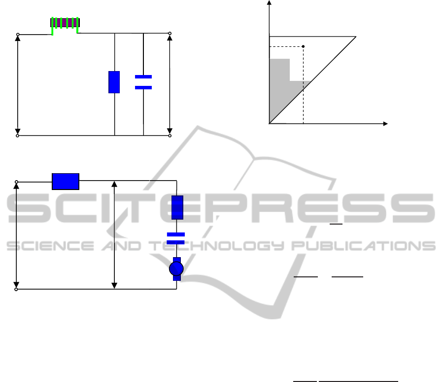
Fig. 2 shows the sketch of deduced RLC electrical
dynamics of the voltage amplifier where the amplify-
ing factor is not presented. R
V
, L
V
and C
V
represent
the resistance, inductance and capacitance of the volt-
age amplifier, respectively. u
0
and u represents the
input and output voltage, respectively. Then,
U(s)
U
0
(s)
=
1/(L
V
C
V
)
s
2
+ s/(R
V
C
V
) + 1/(L
V
C
V
)
, (1)
Let ω
n1
= 1/
√
LC and ξ
n1
= 1/(2R
V
)
√
L
V
C
V
, equa-
tion (1) can be rewritten as
U(s)
U
0
(s)
=
ω
2
n1
s
2
+ 2ξ
n1
ω
n1
s+ ω
2
n1
. (2)
2.2 Preisach Hysteresis Model
The hysteresis effect of PZT material (stack) are
described using Preisach model. Fig. 3 shows the
hysteresis effect and RC electrical dynamics in the
PZT stack. Γ represents the hysteresis effect. R and
C represent the resistance and capacitance of the PZT
stack, respectively. T
em
represents the electromechan-
ical transformer ratio of the PZT material. i is the
conductor current, u is the input voltage of the PZT
stack, u
p
is the effective voltage for the PZT stack.
The hysteresis between the input voltage and
the effective PZT voltage can be represented as
the following Preisach model (Mayergozy, 2003)
ICINCO2014-11thInternationalConferenceonInformaticsinControl,AutomationandRobotics
442
V
C
V
R
V
L
u
0
u
Figure 2: Electrical dynamics of the voltage amplifier.
C
R
p
u
u
Γ
i
em
T
Figure 3: Hysteresis effect and electrical dynamics in the
PZT stack.
u
p
= Γ(u) =
ZZ
S
+
µ(α,β)γ
αβ
[u(t)]dαdβ, (3)
where µ(α,β) and γ
αβ
are the density function and
hysteron output of point α,β on the Preisach plane,
respectively. The Preisach model is rate-independent,
i.e. it is a static model.
Fig. 4 shows the Preisach plane. The shadowing
area S
+
is activated with the γ
αβ
of one. The blank
area S
−
is unactivated with the γ
αβ
of zero.
2.3 RC Electrical Model of the PZT
Stack
In the electrical field of the PZT stack, the voltage
drop u
p
is represented by
u
p
= iR + u
c
, (4)
where R is the resistance and i is the current. u
c
is
the voltage of the equivalent capacitor C of the PZT
stack. u
c
can be represented by
u
c
= QC, (5)
where Q is the charge.
S
+
S
−
( )
V
β
( )
V
α
( )
,
µ
α
β
Figure 4: Preisach plane: S
+
represents the actuated area
with the γ
αβ
of one, S
−
represents the unactuated area with
the γ
αβ
of zero, and µ(α,β) represents the density function
at the point (α,β).
Additionally, the conduction current i is repre-
sented by
i =
dQ
dt
, (6)
By combining equations (4), (5) and (6), the elec-
trical dynamics is written as
Q(s)
U
p
(s)
=
C
(1+ τs)
, (7)
where s is the Laplace operator τ = RC.
In summary, the electrical dynamics in PMS con-
sists of the electrical dynamics of the voltage ampli-
fier and the electrical dynamics of the PZT material.
By combining equations (2) and (7), the electrical
model of PMS is given by
G
e
(s) =
C
1+ τs
ω
2
n1
s
2
+ 2ξ
n1
ω
n1
s+ ω
2
n1
. (8)
The force F due to the inverse piezoelectricity ef-
fect of the PZT stack is written as
F = T
em
Q, (9)
where T
em
the electromechanical transformer ratio
due to the inverse piezoelectric effect.
2.4 Mechanical Vibration Dynamics
A typical mechanical strut with motion amplification
is considered in this paper, as shown in Fig. 5. The
proposed PMS can be used to compensate jitters and
micro vibrations of spacecrafts. The stiff and damp-
ing of the PZT stack as well as the passive isolator and
flexible joints are contained in the mechanical vibra-
tion dynamics. Rubber cushion between the working
platform and the base can be used to introduce damp-
ing for passive isolation.
The mechanical motions of PMS are driven by the
ModelingandH∞CompositeControloftheCoupledHystereticDynamicsinPiezoelectricMicro-displacementSystems
443
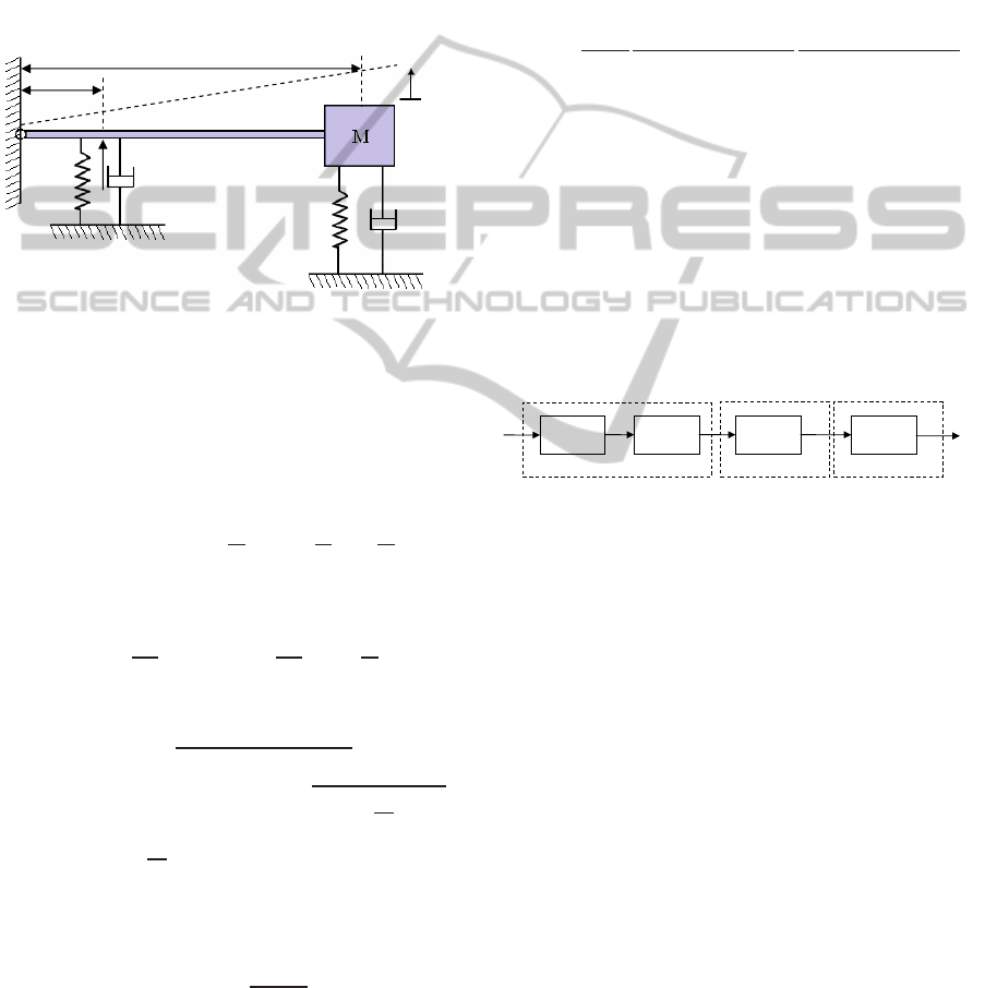
force F due to the inverse piezoelectricity effect. Fig.
5 shows the mechanical vibration dynamics. K
p
and
C
p
represent the stiff and damping of the PZT stack,
respectively. K
f
and C
f
represent the stiff and damp-
ing of the passive isolation and the flexure guide. x
represents the displacement of the arm tip which is
generally attached to a working platform. θ repre-
sents the tilt angle due to the piezo displacement. L
represents the length of the motion amplifying arm.
N represents the amplifying value of the motion am-
plifying arm.
θ
L
/
L N
x
p
K
p
C
f
C
f
K
F
Figure 5: Mechanical vibration dynamics of the PMS with
motion amplification.
For PMS, only micro displacement is provided.
For instance, the maximum displacement of a typ-
ical PMS is 50µm. Compared with its arm length
L = 10cm, tanθ = x
L < 0.0005.Thus, θ
.
= tanθ.
x = Lθ. According to Newton’s law, the dynamics
of M can be written as
J
¨
θ+ K
f
xL+C
f
˙xL+ K
p
x
p
L
N
+C
p
˙x
p
L
N
= F
L
N
, (10)
where J = ML
2
and x
p
= x/N.
Equation (10) can be written as
M ¨x+
C
f
+
C
p
N
2
˙x+
K
f
+
K
p
N
2
x =
F
N
. (11)
Then,
G
v
(s) = k
v
ω
2
n2
s
2
+ 2ξ
n2
ω
n2
s+ ω
2
n2
, (12)
where G
v
(s) = X (s)/Q(s), ω
n2
=
r
C
f
+
C
p
N
2
.
M,
2ξ
n2
ω
n2
=
K
f
+
K
p
N
2
.
M, K
v
= T
em
/
K
f
+ K
p
/N
2
Finally, there exists the creep effect (also named
drift) in PZT material. The creep effect can be repre-
sented by (Devasia and Moheimani, 2007)
G
c
(s) = k
c
m
∏
i=1
s+ z
ci
s+ p
ci
, (13)
where k
c
is the creep gain when s goes to infinity, i.e.
k
c
represents the creep gain at infinite frequencies. m
is the creep order. p
ci
and z
ci
are the poles and zeros
of the creep dynamics, respectively.
2.5 Multi-field Hysteretic Dynamics
The multi-field hysteretic dynamics of PMS can be di-
vided into the static hysteresis and the non-hysteretic
dynamics. In this paper, the static hysteresis is
represented by classical Preisach model. The non-
hysteretic dynamics comprises of the creep, electrical
and vibration dynamics.
By combining equations (8) and (12), the electric
and mechanical dynamics can be presented as
G
ev
(s) =
k
ev
1+ τs
ω
2
n1
s
2
+ 2ξ
n1
ω
n1
s+ ω
2
n1
ω
2
n2
s
2
+ 2ξ
n2
ω
n2
s+ ω
2
n2
(14)
where k
ev
= k
v
C.
Fig. 6 shows the model sketch of the multi-field
hysteretic dynamics in PMS. The cascade connection
is used to represent the relationship among the com-
ponents of the hysteretic dynamics. The hysteresis ef-
fect and creep effect are built in the material field. The
electrical dynamics is built in the electrical field. The
vibration dynamics is built in the mechanical field.
The non-hysteretic dynamics G can be summarized
as G = G
c
G
e
G
v
.
H
c
G
e
G
v
G
u
x
Electrical field
Material field
Mechanical field
Figure 6: Multi-field dynamics of PMS.
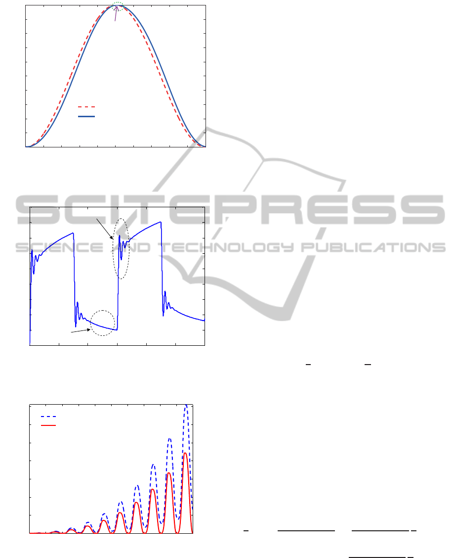
2.6 Characteristics of the Coupled
Hysteretic Dynamics
In this section, the responses of typical PMS are pro-
posed. Fig. 7 shows the response of the static Preisach
hysteresis under sinusoidal inputs. Compared with
phase delay in linear dynamics, the Preisach hystere-
sis achieve its peak value simultaneously with the in-
put signal, i.e., there is not delay at the peak point.
Moreover, the Preisach output is not differential at the
peak point.
Fig. 8 shows the response of the creep, electri-
cal and vibration dynamics under square inputs. It
can be seen that the electrical and vibration dynamics
behaves fast, but the creep dynamics behaves slow.
Moreover, the creep, electrical and vibration dynam-
ics are coupled.
Fig. 9 shows the response of the hysteresis, creep,
electrical and vibration dynamics under slow sinu-
soidal inputs with varying amplitudes. As the input
continues, the drift due to the creep and low frequency
electrical and vibration dynamics are obvious.
ICINCO2014-11thInternationalConferenceonInformaticsinControl,AutomationandRobotics
444
98 98.2 98.4 98.6 98.8 99 99.2 99.4 99.6 99.8 100
0
0.1
0.2
0.3
0.4
0.5
0.6
0.7
0.8
0.9
1
Time (s)
Normalized voltage/displacement
Input voltage
Piezo displacement
No delay at
peak point
Figure 7: Response of the Preisach hysteresis under sinu-
soidal inputs.
0 1 2 3 4 5 6
0
20
40
60
80
100
120
140
160
180
Time (s)
Displacement (nm)
Electrical and vibration
Creep
Figure 8: Response of the creep, electrical and vibration
dynamics.
0 1 2 3 4 5 6 7 8 9 10
0
1
2
3
4
5
6
7
Time (s)
Piezo displacement with creep suppression (µm)
Creep displacement
Creep suppressed displacement
Figure 9: Response of creep effect under the sinusoidal in-
put with varying amplitudes.
3 COMPOSITE CONTROL
ANALYSIS
The proposed composite controller is analyzed in this
section. First, using the reference signal r, the model-
based inversion feedforward controller K
FF
of PMS
can be written as
K
FF
=
ˆ
G
−1
ˆ
Γ
−1
(r), (15)
where the hysteresis estimation
ˆ
Γ is strong nonlinear-
ities with global memories(Mayergozy,2003).
ˆ
Γ(r) is
computed using Preisach model in equation (3).
ˆ
G
−1
and
ˆ
Γ
−1
can be represented as
ˆ
G
−1
= G
−1
(1+ δ
l
)
ˆ
Γ
−1
= Γ
−1
(1+ δ
h
)
,
where δ
l
denotes the inversion error of the non-
hysteretic dynamics and δ
h
denotes the inversion er-
ror of the rate-independent hysteresis. δ
l
and δ
h
are
bounded uncertainties and determined by the identifi-
cation accuracy of PMS. Then,
ˆ
Γ
−1
(r) and
ˆ
G
−1
can
be rewritten as
ˆ
G
−1
ˆ
Γ
−1
(r) = (1+ δ
l
+ δ
h
+ δ
l
δ
h
)G
−1
Γ
−1
(r). (16)
Let δ = δ
l
+ δ
h
+ δ
l
δ
h
, the model-based inversion
feedforward controller of PMS is rewritten as
K
FF
= (1 + δ)G
−1
Γ
−1
(r). (17)
With only the feedforward controller K
FF
in (17),
the relative error in e/r is given by
e
r
|
K
FB
=0
= δ +
d
r
. (18)
Equation (18) indicates that the tracking perfor-
mance of feedforward relies on the identification ac-
curacy and the output disturbances are not suppressed.
Thus, feedback control is necessary to guarantee the
stability and robustness under modeling error δ and
disturbance d.
Fig. 10 shows the proposed composite control
strategy where
ˆ
G
−1
and
ˆ
Γ
−1
are represented by G
−1
and Γ
−1
according to (17), respectively. With the pro-
posed composite control, the relationship between the
reference r and PMS displacement output y is written
as
y
r
= 1 +
1
GΓ(u)K
FB
+ 1
δ+
GΓ(u)K
FB
GΓ(u)K
FB
+ 1
n
r
+
1
GΓ(u)K
FB
+ 1
d
r
, (19)
where K
FB
denotes the feedback controller, n and d
are the measurement noise and output disturbance, re-
spectively. Γ(u) is computed using Preisach model in
equation (3).
ModelingandH∞CompositeControloftheCoupledHystereticDynamicsinPiezoelectricMicro-displacementSystems
445

G
r
y
−
+
n
Γ
+
1
−
Γ
1
G
−
r
v
v
ff
u
fb
u
δ
FF
K
+
+
d
FB
K
Figure 10: Analysis of proposed composite control strategy.
Then, the relationship between the reference r and
tracking error e is represented as
e
r
=
1
GΓ(r)K
FB
+ 1
δ+
1
GΓ(u)K
FB
+ 1
d
r
+
GΓ(u)K
FB
GΓ(u)K
FB
+ 1
n
r
. (20)
The feedback controller K
FB
is designed to sup-
press the output disturbance d and the feedforward
error δ, but the measurement noise n is amplified in
the feedback bandwidth. If the feedback bandwidth is
too large, some signals in noise n may coincide with
mode frequencies of PMS, which will result in chat-
tering and unstable responses. Thus, multi-objective
robust H
∞
control is necessary to design K
FB
. The dif-
ferent objectives of the feedback controller are speci-
fied at different frequencies.
4 H
∞
COMPOSITE CONTROL
The proposed H
∞
composite control consists of a H
∞
feedback controller and an inversion-based feedfor-
ward controller.
4.1 H
∞
Controller Design
The loop shaping is employed to design the feedback
controller as shown in Fig. 11. The performance and
stability requirements are satisfied by specifying L
1
and L
2
. ω
c
is the cross frequency of GK
FB
and is
related and close to feedback bandwidth, ω
p
is re-
lated to disturbance rejection performance, and ω
s
is
related to the robust stability under modeling errors,
disturbances and measurement noise at high frequen-
cies.
Weighting functions are suitable for specifying
different requirements at different frequencies as
shown in Fig. 11. It is convenient to achieve multi
objectives using weighting functions(Skogestad and
Postlethwaite, 2005). The robust H
∞
controller is de-
signed based on the non-hysteresis dynamics, while
p
ω
s
ω
Robust stability range
FB
GK
Performance
range
c
ω
(
)
Hz
f
1
L
2
L
Magnitude (dB)
Figure 11: Illustration of loop shaping.
the rate-independent hysteresis Γ can be regarded as
an input uncertainty consisting of the nominal gain k
h
and the weighting function w
u
.
Fig. 12 shows the sketch of multi-objective robust
H
∞
control. w
1
is the performance weighting function
to specify performance requirements and achieve fine
tracking. Significant vibrations are easily induced by
high gain at high frequencies. Then, an integral ac-
tion is added to w
1
to reduce the feedback bandwidth
and enhance the disturbance suppressing at low fre-
quencies. w
n
and w
r
denote the noise and reference
weighting functions, respectively, w
2
is the control
weighting function to limit the control gain and sup-
press noise at high frequencies, w
u
denotes the uncer-
tainty due to the hysteresis nonlinearity, ∆
u
is an unit
complex uncertainty with norm k∆
u
k < 1.
r
w
2
w
u
∆
r
u
w
−
+
n
w
+
2
z
FB
K
G
n
1
w
1
z
Input uncertainty
h
k
δ
d
w
d
y
+
+
Figure 12: Illustration of multi-objective H
∞
control.
Weighting functions w
1
and w
2
are used to satisfy
the trajectory of GK
FB
that is bounded by L
1
and L
2
.
The relationships are as follow
w
1
|
ω≤ω
p
= L
1
w
2
|
ω≥ω
s
= 1/L
2
. (21)
4.2 Inversion-based Feedforward
Compensation
The feedforward controller is used to overcome the
bandwidth limitation of the feedback controller. In
this section, an inversion-based feedforward con-
troller is used to enhance the H
∞
feedback perfor-
mance.
ICINCO2014-11thInternationalConferenceonInformaticsinControl,AutomationandRobotics
446

The inversion-based feedforward controller en-
compasses the inverse non-hysteretic dynamics and
the inverse hysteresis. First, the reference signals pass
through the inverse non-hysteresis dynamics
ˆ
G
−1
,
then the inverse hysteresis
ˆ
Γ
−1
. The details of the
model-based inversion
ˆ
G
−1
can be found in Refs.(Liu
and Lee, 2013b). The Preisach-based inversion
ˆ
Γ
−1
is shown in (Liu and Lee, 2012). The inversion of the
non-hysteretic dynamics can be represented as
ˆ
G
−1
(s) =
ˆ
τs+ 1
ˆ
k
ev
m
∏
i=1
s+ ˆp
i
s+ ˆz
i
·
2
∏
i
(s
2
+ 2
ˆ
ξ
ni
ˆ
ω
ni
s+
ˆ
ω
2
ni
)
ω
2
ni
,
(22)
where
ˆ
k
ev
,
ˆ
τ,
ˆ
ξ
ni
and
ˆ
ω
ni
are the identified parameters
of the electric and vibration dynamics, respectively, ˆz
i
and ˆp
i
are the estimated zeros and poles of the creep
dynamics, respectively.
5 EXPERIMENTAL STUDIES
5.1 Experimental Setup
The experimental setup consists of a piezoelectric ac-
tuator with motion amplification, an voltage amplifier,
a linear variable differential transformer(LVDT) and
a DSPACE 1104 board. Fig. 13 shows the piezoelec-
tric actuator. The actuator has a travel span of 80µm.
The amplifier is E-662 with the output voltage range
of [−20,120]V. The LVDT sensor has white noise,
and the RMS value of sensor noise is 0.01µm. MAT-
LAB/Simulink and a dSPACE DS1104 board are used
to implement the model-based controller.
Figure 13: Piezoelectric actuator (PA) in the experiment.
The electric and vibration dynamics are identified
as
ˆ
G
ev
(s) =
1
0.000474s+1
·
8.111×10
6
s
2
+ 3786s+8.111×10
6
·
2.478×10
7
s
2
+ 809.1s+2.478×10
7
.
(23)
The creep dynamics is identified as
ˆ
G
c
(s) =
(s+ 0.0146)(s+ 0.172)(s+ 0.241)
(s+ 0.0142)(s+ 0.169)(s+ 0.2402)
·
(s+ 1.07)(s+ 18.29)
(s+ 1.053)(s+ 17.57)
. (24)
Fig. 14 shows the identified density function µ(α,β)
in equation (3).
Figure 14: Identified density function µ(α,β).
5.2 Controller Parameters
The performance weighting function w
1
and the con-
trol weighting function w
2
are set to
w
1
=
350π
s+ 0.0001
. (25)
w
2
= 0.1
s+ 1000π
s+ 10000π
. (26)
The reference signal and measurement noise are
represented using the weighting functions w
r
, w
d
and
w
n
, respectively
w
r
= 0.1,w
n
= 0.0001.
To reduce the conservation, the discrete D-K it-
eration with structured singular value (SSV) is used
to solve the controller(Skogestad and Postlethwaite,
2005). After 6 iterations, the SSV is less than 0.98,
and the order of the H
∞
controller is 9. To easily im-
plement the controller in DSP, the H
∞
controller with
order of 4 is given by
K
FB
= 1903075
(s+ 31360)(s+ 566.9)(s+ 0.313)
(s+ 19830)(s+ 2951)(s+ 923.7)
.
(27)
5.3 Experimental Result
In this paper, square and sinusoidal references are
used to demonstrate the effectiveness of the proposed
ModelingandH∞CompositeControloftheCoupledHystereticDynamicsinPiezoelectricMicro-displacementSystems
447

composite control. Further, the root-mean-square
(RMS) error e
rms
is used to measure the tracking er-
rors.
Fig. 15 shows the tracking performance of the
square reference at 20Hz. The RMS tracking error
is 0.19µm (To grantee the differential of the reference
signal, a pre-filer is used for inversion-based feedfor-
ward). Fig. 16 shows the control voltage. Further,
Fig. 17 shows the tracking performance of the sinu-
soidal trajectory at 600Hz. The RMS tracking error
is 0.78µm. Fig. 18 shows the control voltage of the
sinusoidal tracking at 600Hz.
The experimental results demonstrate that the pro-
posed composite control provides precision tracking
performance at broadband frequencies.
0 0.02 0.04 0.06 0.08 0.1 0.12 0.14 0.16 0.18 0.2
0.5
1
1.5
2
2.5
Piezo displacement (µm)
Measured displacement
Reference displment
0 0.02 0.04 0.06 0.08 0.1 0.12 0.14 0.16 0.18 0.2
−2
−1
0
1
2
Time (s)
Tracking error (µm)
Figure 15: Tracking performance of square inputs at 20Hz.
0 0.02 0.04 0.06 0.08 0.1 0.12 0.14 0.16 0.18 0.2
6
8
10
12
Time (s)
Control voltage (V)
Figure 16: Control voltage at 20Hz.
6 CONCLUSIONS
It is increasingly demanded to present broadband ac-
curate tracking of PMS. The modeling and H
∞
com-
posite control of the coupled hysteretic dynamics is
thus provided in this paper. The Preisach hystere-
sis, creep, electrical and vibration dynamics are devel-
oped to describe the complex behaviors of PMS. The
proposed hysteretic dynamics has physical meanings
which is useful for deep developments of PMS. The
1.8 1.802 1.804 1.806 1.808 1.81 1.812 1.814 1.816 1.818 1.82
0
5
10
15
20
Piezo displacement (µm)
1.8 1.802 1.804 1.806 1.808 1.81 1.812 1.814 1.816 1.818 1.82
−2
−1
0
1
2
Time (s)
Tracking error (µm)
Measured displacement
Reference dispacelment
Figure 17: Tracking performance at 600Hz
1.8 1.802 1.804 1.806 1.808 1.81 1.812 1.814 1.816 1.818 1.82
−20
0
20
40
Time (s)
Control voltage (V)
Figure 18: Control voltage at 600Hz.
proposed H
∞
composite control provides high-speed
and precision tracking. The experimental studies
demonstrate the effectiveness of the proposed mod-
eling and control approaches.
The proposed modeling and control approaches
of PMS are beneficial to the suppression of jitters
and micro-vibrations in precision spacecrafts, such as
inter-satellite laser communication, staring cameras,
space-based interferometers and space telescopes.
REFERENCES
Brokate, M. and Sprekels, J. (1996). Hysteresis and Phase
Transitions. Springer-Verlag, Berlin-Heidelberg-
NewYork.
Clayton, G., T. S. L. K.-Z. Q. and Devasia, S. (2009). A
review of feedforward control approaches in nanopo-
sitioning for high-speed SPM. ASME J. Dyn. Syst.
Control, 131(6):061101.
Devasia, S., E. E. and Moheimani, S. (2007). A survey of
control issues in nanopositioning. IEEE Trans. Con-
trol Syst. Technol., 15(5):802–823.
Dewella, L., P. N. and Blaurockb, C. (2005). Precision tele-
scope pointing and spacecraft vibration isolation for
the terrestrial planet finder coronagraph. Preceding of
SPIE conference on UV/Optical/IR Space Telescopes:
Innovative Technologies and Concepts. Bellingham,
2005, vol. 5899, pp. 589902.
ICINCO2014-11thInternationalConferenceonInformaticsinControl,AutomationandRobotics
448

Fleming, A. (2010). Nanapositioning system with force
feedback for high performance tracking and vibration
control. IEEE/ASME Trans. Mechatron., 15(3):433–
446.
Janaiden, M. and Rakheja, S. (2008). Development of the
rate-dependent Prandtl-Ishlinskii model for smart ac-
tuators. Smart Mater. Struc., 7:035026.
Jiang, H., J. H. Q. J. and Chen, Y. (2010). A modi-
fied Prandtl-Ishlinskii model for modeling asymmet-
ric hysteresis of piezoelectric actuators. IEEE Trans-
actions on Ultrasonics, Ferroelectrics, and Frequency
Control, 57(5):1200–1210.
Kamesha, D., P. R. and Ghosalb, A. (2010). Modeling, de-
sign and analysis of low frequency platform for atten-
uating micro-vibration in spacecraft. Journal of Sound
and Vibration, 329(17):3431–3450.
Laneand, S. and Lacy, S. (2008). Active vibration control of
a deployable optical telescope. Journal of Spacecraft
and Rocket, 45(3):568–586.
Leaning, K. K. and Devasia, S. (2007). Feedback linearized
inverse feedforward for creep, hysteresis and vibration
compensation in AFM piezoactuators. IEEE Trans.
Control Syst. Technol., 15(5):927–935.
Liaw, H. and Shirinzadeh, B. (2009). Neural net-
work motion tracking control of piezo actuated flex-
ure based mechanisms for micro nanomanipulation.
IEEE/ASME Trans. Mechatron., 14(5):517–27.
Liu, L., T. K. and Lee, T. H. (2012). SVD-based preisach
hysteresis identification and composite control of
piezo actuators. ISA Trans., 51(3):430–438.
Liu, L., T. K. C. S.-L. T. C. and Lee, T. H. (2013a). Dis-
crete composite control of piezoelectric actuators for
high speed precision scanning. IEEE Transactions on
Industrial Informatics, 9(3):859–868.
Liu, L., T. K. T. C.-C. S.-L. and Lee, T. H. (2013b). Devel-
opment of an approach toward comprehensive identi-
fication of hysteretic dynamics in piezoelectric actua-
tors. IEEE Trans. Control Syst. Technol., 21(5):1834–
1845.
Maillarda, T., C. F. and LeLettya, R. (2009). Piezo mecha-
tronic based systems in aircraft, space and defense ap-
plications. Space Exploration Technologies II, 2009,
vol. 7331, pp. 73310K.
Mayergozy, I. (2003). Mathematical Modeling of Hystere-
sis and Their Application. Elsevier, Amsterdam, 2nd
edition.
McMickell, M., K. T. and Hansen, E. (2007). Optical pay-
load isolation using the Miniature Vibration Isolation
System (MVIS-II). SPIE Industrial and Commercial
Applications of Smart Structures Technologies, vol.
6527, pp.652703.
Nagashima, M. and Agrawal, B. (2014). Active control of
adaptive optics system in a large segmented mirror
telescope. International Journal of Systems Science,
45(2):159–175.
Neat, G., A. A. and Goullioud, R. (1998). Overview of the
micro precision interferometer testbed. Philadelphia.
American Control Conference, pp.1563–1568.
Shieh, H.-J. and Hsu, C.-H. (2008). An adaptive
approximator-based backstepping control approach
for piezoactuator-driven stages. IEEE Trans. Ind.
Electron., 55(4):1729–38.
Skogestad, S. and Postlethwaite, I. (2005). Multivariable
Feedback Control: Design and Analysis. John Wiley
and Sons Ltd, Chichester, 2nd edition.
Tan, U., L. W. S. C.-R. C. N. and Ang, W. T. (2009). Feed-
forward controller of ill-conditioned hysteresis using
singularity-free Prandtl-Ishlinskii model. IEEE/ASME
Trans. Mechatron., 14(5):598–605.
Wu, Y. and Zou, Q. (2009). Robust inversion-based 2-
DOF control design for output tracking: piezoelectric-
actuator example. IEEE Trans. Control. Syst. Tech-
nol., 17(5):1069–1082.
ModelingandH∞CompositeControloftheCoupledHystereticDynamicsinPiezoelectricMicro-displacementSystems
449
