
Detection of Mechanical Play of Revolute Robot Joint
Radim Luˇza and Frantiˇsek V. Zboˇril
Faculty of Information Technology, Brno University of Technology, Boˇztˇechova 2, Brno, Czech Republic
Keywords:
Play Detection, Revolute Joint, Robotic Manipulator, Mechanical Oscilator.
Abstract:
This article introduces a method of detection of mechanical play of revolute joint based on recognition of
impacts caused by the play. The method uses inexpensive acceleration measuring device with limited sampling
frequency. The impact is recognized indirecly according to oscillation of mechanical oscilator. The method
was tested on real servo drive Dynamixel AX-12A.
1 INTRODUCTION
In todays world robots equipped with manipulators
are rather widespread and they are becoming still
more casual. They are being used for tasks of many
different kinds. Precise control of the robotic manip-
ulator is essential for most of them. Controller of
robotic manipulator has to deal with kinematic and
dynamic properties and constraints of the manipula-
tor and payload it carries. A lot of effort was in-
vested into exploring areas of manipulator kinematics
and dynamics with rather impressive results. Today
there are software tools and simulators for simula-
tion of manipulators forward kinematics and forward
and backward dynamics like Gazebo (Koenig and
Howard, 2004) or Webots (Michel, 2004), libraries
of algorithms for solving inverse kinematics prob-
lem and planning trajectory of the motion for most of
kinds of manipulators like OMPL (S¸ucan et al., 2012)
and also tools that automate process of finding effec-
tive analytic inverse kinematics solvers for open kine-
matic chain manipulators (with some constraints) like
OpenRAVE (Diankov, 2010).
Often used way of controlling a robotic manipula-
tor is based on simulation. The controller has precise
model of manipulator it controls and before it moves
the real manipulator it finds and tests the motion with
the simulated one. Controllers of this kind are rather
robust and can be used with manipulators of many dif-
ferent kinds without need of changing their internal
structure. Especially if they use planners and solvers
based on iterative numerical algorithms.
Precision of controlers based on simulation is usu-
ally limited by conformity of model and real manip-
ulator. Basic kinematic parameters of the manipula-
tor - sizes of links, joint limits, link bounding objects
- are usually available as a part of production docu-
mentation of manipulator and these values are usually
precise. For measurement of manipulator dynamic
parameters there are several algorithms like (Gautier
M., Janot A., Vandanjon P.O., 2008) and others that
provide results usually with good precision. Theo-
retically identification algorithms are limited only by
precision of used sensors - mostly encoders in joints
of robotic arm. Unfortunatelly precision of identifi-
cation procedure aimed on obtaining parameters of
robotic arm manipulator is limited by properties of
the manipulator that are difficult to identify. One of
them is mechanical play (backlash). Mechanical play
is difficult to identify in general. Play can be hardly
detected by joint encoder beacuse its resolution is
usually limited. Identification is especially difficult
if manipulator has encoders installed on joint motors
instead of joint axis to increase resolution of position
measurement. Disadvantage of this solution is that the
mechanical play between gears of gearbox and play
of bearings can not be measured by encoder. Anyway
mechanicalplay is one of aspects that make difference
between real manipulator and identified model.
2 MECHANICAL PLAY OF
REVOLUTE JOINT
Most of robotic manipulators use at least one revo-
lute joint. Revolute joints have evolved from simple
joints with one degree of freedom (DOF) to two DOF
joints with differential drive or three DOF robotic
wrist (Meng Li, 2003). Play in revolte joints causes
327
Luža R. and Zboril F..
Detection of Mechanical Play of Revolute Robot Joint.
DOI: 10.5220/0005018203270332
In Proceedings of the 11th International Conference on Informatics in Control, Automation and Robotics (ICINCO-2014), pages 327-332
ISBN: 978-989-758-040-6
Copyright
c
2014 SCITEPRESS (Science and Technology Publications, Lda.)

imprecision of end effector positioning. The longer
the manipulator link is the more significant the effect
of a play is. According to intallation of encoder there
are two solutions used in revolute joints: with encoder
connected with the motor and with encoder connected
with joint axis. In a typical construction of articulated
revolute joint the encoder is connected directly with
the motor. In this construction play of gearbox can not
be detected by encoder. This construction is modeled
by model described in (Ahmad, 1985). Mechanical
play in this model is given by gaps between teeth of
gears, by play of bearings and also by dynamic defor-
mation of gearbox. When motor of the joint starts to
move it has to overcome gap caused by play so part of
its motion is lost compared to output of encoder. This
effect is called lost motion (Ahmad, 1985).
Another construction of articulated revolute joint
typical for small servo drives uses high resolution
encoder or potentiometer connected with joint axis.
This solution is theoretically capable of detecting me-
chanical play of gearbox. If resolution of the encoder
is high enought it is possible to detect play of arm link
caused by gaps between gears by change of encoder
value. Practically the play would have to be bigger
than encoder step which can not be infinite small. For
example in case of Dynamixel AX-12A servo drive
(Collective of employees of ROBOTIS ComSchool ef
Electrical Engineering, 2006) the encoder has 1024
steps per rotation which means that the lost motion
would have to be more then or equal to 21’ (angular
minutes). This value multiplied by length of link con-
nected to the joint gives us a length of an arc that end
of link can traverse without noticing by encoder.
2.1 Model of Play between Two Spur
Gears
Typically the most significant source of play in rev-
olute robot joints are gaps between teeth of gears in
gearbox of the joint. Play caused by spur gears is
usually much bigger than play caused by bearings -
especially in case of inexpensive servo drives. For
this reason we decided to simplify model of play to
model play caused by spur gears only. Model of force
transmission between gears we use was presented in
(R. Kalantari, 2009). For each pair of spur gears the
model of contact force is following:
F
cnt
= F
k
+ F
c
= β ·
∆d
d/2
n
+ α·∆v ·
∆d
d/2
n+1
(1)
In equation 1 the F
k
member is an elastic force
and the F
c
is a viscous force. The ∆v is a difference
of linear speed of gears at the point of contact, the ∆d
is a difference between linear positions of spur gears
at the point of contact and the α and β coeficients are
special constants that convertforces to proper size and
unit. The exponent n is a large odd number.
In the model of spur gears the first gear is actuated
by ideal actuator with no inertia, no backlash and infi-
nite torque. This actuator changes position of the first
gear with index 1. The second gears with index 2 is
is actuated by the first gears through teeth with back-
lash. Force between teeth is described by equation 1.
The F
cnt
force causes angular acceleration of the sec-
ond gear. The angular acceleration is given by inertia
J
2
of the second gear and its radius R
2
according to
equation 2.
ω
′
= −
F
cnt
R
2
J
2
. (2)
Change of position of particular tooth on each gear
is given by corresponding relation in 3 where θ de-
notes angular position of particular gear.
p
1
= θ
1
·R
1
; p
2
= θ
2
·R
2
(3)
The shift between teeth of gears required for com-
putation of the contact force F
cnt
is described by equa-
tion 4. The difference between linear speeds of teeth
at the point of contact of the gears is given by equation
5 in a similar way.
∆d = p
2
− p
1
(4)
∆v = p
′
2
− p
′
1
(5)
Response of the model of spur gears with play can
be observed in figure 1. As input signal for the model
the sine signal at frequency 6 Hz was used. The input
signal controls angular position θ
1
of the first gear.
It is a simplification that we can use thanks to ideal
actuator with infinite torque so inertia of the first gear
has no effect and we can neglect it.
In the figure we can see that the gaps between
teeth cause visible peak in angular acceleration of
the second gear. The peak in acceleration practically
means that the contact of gears that are spinning each
with different angular speed cause impact.
2.2 Current Methods of Measuring and
Compensation of Mechanical Play
Currently the most of effort is aimed on elimination
of the play itself. Elimination of mechanical play
includes sophisticated design of gearbox and a very
precise manufacturing of manipulator parts. Elimi-
nating the play is absolutely the best solution. Unfor-
tunatelly this solution is very expensive. It is usable
for industrial manipulators which save a lot of money
by doing mechanical work effectivelyand their higher
ICINCO2014-11thInternationalConferenceonInformaticsinControl,AutomationandRobotics
328
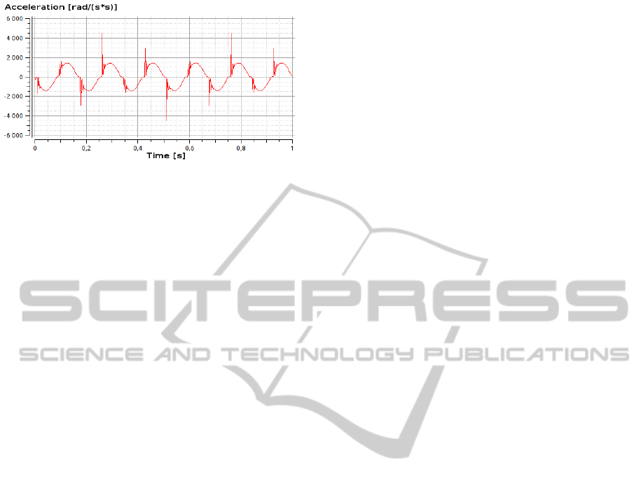
Figure 1: Response of spur gear model with backlash to sine
excitation.
initial price is not a problem. But in case of experi-
mental and prototype manipulators a high initial price
is a serious problem. Experimental manipulators are
usually built of inexpensiveserial parts. They are usu-
ally equipped with common bearings and inexpensive
joint drives. With such a low cost construction it is
usually difficult to avoid mechanical play. Moreover
there is also higher probability of quick wear out or
mechanical damage of the manipulator. In case of
low-cost experimental manipulators it is useful to be
able to detect and measure mechanical play.
Measuring and compensation of mechanical play
is described in (Ahmad, 1985) and (Hyun-Kyu Lim
and Kang, 2009). In (Ahmad, 1985) imprecision of
manipulator caused by several aspecs including play
is compensated according to feedback of human op-
erator who measures total error of manipulator end-
point. The paper also presents procedure leading to
excitation of mechanical play. The effect of play is
mechanical overshoot of desired arm endpoint posi-
tion. The overshoot can be converted into angular
displacement of revolute joint and according to this
displacement the compensating shift in motor angle
is computed. To compensate properly the manipula-
tor controller needs to keep a direction of previous
motion to decide whether mechanical limit given by
play was reached and which one.
In (Hyun-Kyu Lim and Kang, 2009) authors de-
scribe a method of measuring and compensation of
mechanical play for industrial manipulator Hyundai
HS165. The described method iteratively changes
compensation parameters to minimize error between
computed endpoint position and measured endpoint
position. The paper also describes extention of the
original method to include compensation of errors
caused by stiffness of manipulator parts.
Both methods described abovewere developed for
stationary industrial manipulators. They provide very
precise compensation of errors caused by play and
other aspects but they both require very precise mea-
surement of end effector error. The measurement is
done by measuring by hand (Ahmad, 1985) or by ex-
ternal sensors (Hyun-Kyu Lim and Kang, 2009). Un-
fortunatellyprecise external measurement of endpoint
position is usually rather difficult and expensive to re-
alize. Measuring device has to be installed and pre-
cisely calibrated in relation to basepoint of the ma-
nipulator. It may cause difficulties especially in case
of mobile robots where is usually not much space for
proper installation of sensors measuring endpoint po-
sition. In this paper there is proposed an inexpensive
and rather easy to establish method for detecting me-
chanical play based on impact detection.
3 DETECTION OF
MECHANICAL PLAY
In the method proposed below the mechanical play
is detected indirectly by detecting impacts caused by
mechanical play between two moving spur gears in
a gearbox. If there were no gaps between teeth of
gears in the gearbox the input motion would be trans-
ferred to the output affected only by gear ratio. It
means that the output trajectory would have the same
shape as input one. If acceleration of the excitation
motion is sine wave the output of the ideal gearbox
would be also perfect sine wave. In real situation
small gaps between teeth deform output acceleration
trajectory as can be seen in figure 1. The peeks in
acceleration caused by impact when teeth of the first
gear meet the theeth of the second gear are easy to
recognize in simulation but in real measurement it is
not that easy to recognize them. The real measure-
ment contains a lot of noise. The noise also contains
peeks that can easily interfere with peeks caused by
play so detection of play based on detection of peeks
in acceleration would detect many false alarms. The
solution we decided to use also uses the impact peeks
but not directly. In proposed solution acceleration
peeks shake a mechanical oscilator that starts to os-
cilate. The periodic oscilation of the known oscilator
is then much easier to detect.
To model output of the oscilator we used standard
model of damped oscillation described by equation
6. The model is based on principle of preservation of
energy in isolated system. The m coeficient denotes a
generalized mass, b is a breaking coeficient that is re-
sponsible for decreasing of amplitude in time, the k is
a spring elasticity coeficient and the q is a generalized
coordinate.
m·q
′′
+ b·q
′
+ k·q = 0 (6)
This model was interconnected with model of spur
gears with mechanical play described in prior section.
The interconnection was done by adding acceleration
DetectionofMechanicalPlayofRevoluteRobotJoint
329
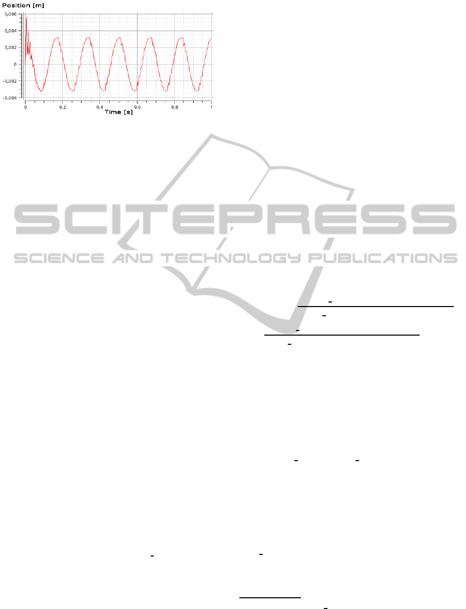
Figure 2: Position of free end of the mechanical oscilator.
caused by motion of the second gear to the accelera-
tion in the equation 6. The oscilator is installed on a
metalic bar connected with one end to the axis of the
second spur gear in a direction orthogonal to the axis.
The lenght of the bar is l and the ω
2
coeficient is an-
gular acceleration of the second spur gear. Equation
7 describes extended damped oscillation model. Ac-
celeration of the oscilator connected to the spur gear
model with the same conditions that were used in pre-
vious section can be observed in figure 2.
m·(q
′′
+ ω
′
2
·l) + b·q
′
+ k·q = 0 (7)
In figure 2 appear small periodic waves in a sine
trajectory of acceleration. These waves are caused by
resonation of the oscilator.
Of course the oscillation of the oscilator causing
fast small periodic change in acceleration mix with
acceleration changes caused by motion of the second
spur gear and with noise but it can be detected in spec-
trum. In spectrum it is possible to to filter out only the
particular frequency - the resonation frequency of the
oscilator - and omit all other frequencies. In spectrum
the presence of oscillation of the oscilator can be de-
tected by amplitude of the resonation frequency of the
oscilator. Despite the theory that tells us that we can
filter out only one particular frequency in real solu-
tion we have to filter out a small range of frequencies
because due to dumping and some parts that shake in
moment of impact the oscillation of the mechanical
oscilator is not perfect. Processing of input signal is
described by following equation. Output of the equa-
tion is a scalar value o that we can compare to some
level value. If o is greater than level value impact is
detected.
o =
∑
norm( f ft(~s
i
), f
norm
, f
norm
w
)
K
~
mask
(8)
Where ~s
i
is a vector of measured values,
~
mask is a
mask vector of ones and zeros and norm is a nor-
malization function that will be decribed later. When
spectrum of input signal computed by fast Fourier
transform from input vector is multiplied element by
element by mask vector, only subsequence of spec-
trum is ”selected” and the rest of elements of spec-
trum vector change to zero in result. Note that
J
de-
notes a Hadamard (elementwise) product of vectors.
There are three parameters that can change be-
haviour of the method and setting their proper val-
ues is essential to reach good reliability. The first
two parameters describe filter that extracts informa-
tion about impact from the spectrum according to
equation (10). These are frequency of resonation of
measurement equipment f
res
and width of detection
window f
width
. Effect of f
res
is rather straightforward.
The window width f
width
on one hand should be wide
enought to not to miss the peak that can become rather
wide in real signals because of imperfect oscillation
as desribed above but on the other hand it can not
be too wide to receive noise. Third parameter that
has significant impact on results of this method is the
level value mentioned above that o
scalar
is compared
to. This level value has the same effect as detection
levels in classificators. The level needs to be tuned to
obtain the best ratio of proper detection to false pos-
itives and false negatives. The optimisation equation
for level value is following:
level =
= argmax
x
correct
accept(eval( f
res
, f
width
,ss,x))
false positive(eval( f
res
, f
width
,ss,x))
+
correct
reject(eval( f
res
, f
width
,ss,x))
false negative(eval( f
res
, f
width
,ss,x))
(9)
Function eval(X,Y, Z) is a funtion that evaluates
runs of the method described above. It runs with
sample set ss and with constant properly set param-
eters f
res
and f
width
and level x which is object of
optimisation. The function returns a matrix of re-
sult values of correctly accepted samples (play de-
tected), correctly rejected samples (play not detected)
and false positive and false negative detections. Func-
tions correct
accept, false positive and others are
functionsthat return value they describe by their name
from the result matrix.
The
~
mask vector compounds of mask
i
compo-
nents. According to resonation frequency of oscila-
tor f
res
and width of detection range f
width
each co-
eficient of masking vector is computed. The com-
putation is defined by following equation. Function
freq
f ft converts real frequency to coeficients of fast
Fourier transform
1
.
1
The function freq
f ft in equation (10) would require
also sampling frequency and cardinality of input vector as
arguments but for better readability of the equation these
parameters were omitted.
ICINCO2014-11thInternationalConferenceonInformaticsinControl,AutomationandRobotics
330
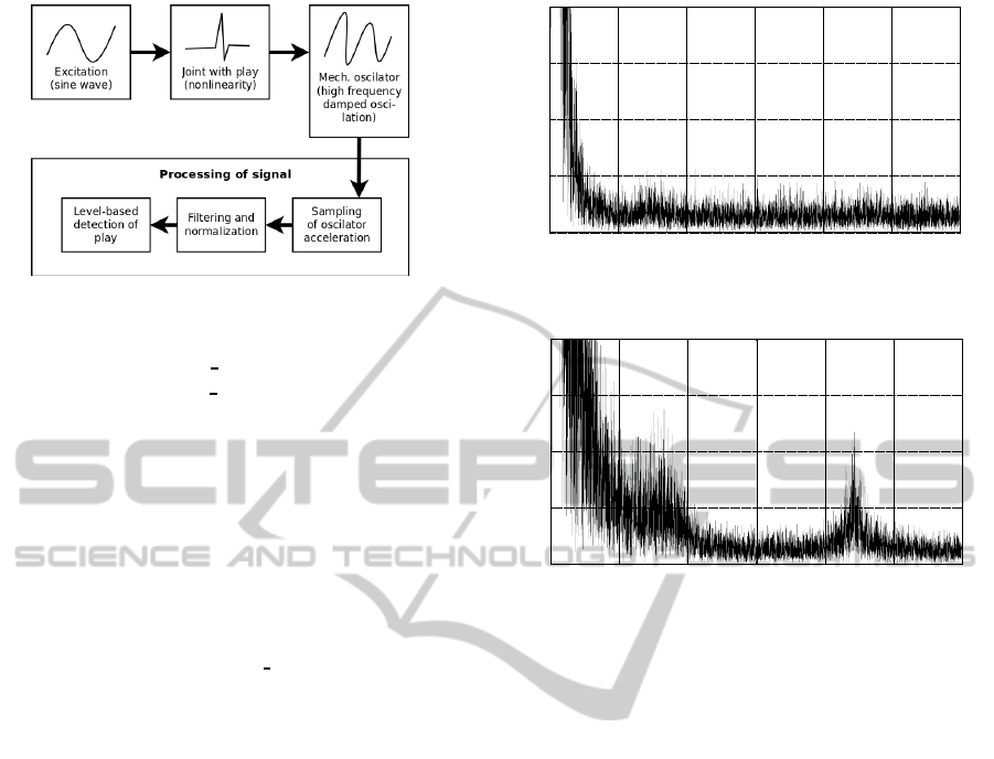
Figure 3: Block diagram of entire solution.
mask
i
=
1,i ∈< freq
f ft(f
res
− f
width
/2)),
freq f ft(f
res
+ f
width
/2)) >
0,otherwise
(10)
Function norm is normalization function. This
function normalizes each sample of spectrum by nor-
malization coeficient. Normalization coeficient is
computed as average of subsequence of amplitude
values extracted from spectrum. The f
norm
argument
defines frequency which will be the center of subse-
quence extracted from vector of spectrum. Length of
the sequence is defined by f
norm
w
. Average of the ex-
tracted sequence is used as normalization value that
divides each element of spectrum vector. Function
norm returns vector of normalized valuesof spectrum.
Complete solution can be observed in figure 3.
As a mechanical oscilator can be theoretically
used any object that will resonate after impact. Theo-
retically the manipulator links themself could be used
as oscilators but practically there are some shortcom-
ings. Usually the robotic manipulator links are robust
and have complicated shape. Due to it manipulator
links have usually very high and hardly predictable
resonation frequency and its resonation is quickly at-
tenuated so detector of oscillation would have to be
extremly sensitive. The sensitivity of the detector
brings a serious problem with noise. This can be
solved by using properly formed metal bar as the os-
cilator. We used a metal bar installed on manipulator
link in direction parallel to direction of manipulator
link - one end is fixed on the manipulator link and
the other free end connected with acceleration sensor.
When impact occurs the metal bar starts to oscilate
like if it was hit by gavel. This way it is possible
to capture oscillation of metal bar when impact oc-
curs in joint of manipulator. Moreover we can change
resonation frequency and intensity of oscillation by
changing shape of the metal bar.
0
5000
10000
15000
20000
0 1000 2000 3000 4000 5000 6000
Amplitude
Fast Fourier Transform coeficients
Figure 4: Spectrum of acceleration during motion without
impact.
0
5000
10000
15000
20000
0 1000 2000 3000 4000 5000 6000
Amplitude
Fast Fourier Transform coeficients
Figure 5: Spectrum of acceleration during motion with im-
pact.
4 EXPERIMENTS AND RESULTS
Initial experiments were done on special experimen-
tal apparatus that is from mechanical point of view
very similar to metal bar with one end fixed to revo-
lute joint and the other end free. To simulate play the
metal bar could rotate between two blocks that limit
its revolute motion - one fixed and the other config-
urable. The entire apparatus rotates about the same
axis as the metal bar inside it does. This apparatus
was useful to prove the concept proposed in prior sec-
tion but its mechanical concept is still rather different
from real joint and links of manipulator. The appa-
ratus demonstrates change in the spectrum when play
appears as is visualized in figures 4 (without play) and
5 (with play).
To prove correctness of principle of the method
it was necessary to execute experiments on a real
robotic joint. A simple robot compounding of two
links connected together by AX-12 revolute servo
drive was used as experimental device. One link was
a fixed base link and the other was free link. On the
free link there was installed measuring device - metal
bar with acceleration sensor. One end of metal bar
was mounted on the free link and the other end with
acceleration sensor was free.
The servo drive has a small play. During the test-
DetectionofMechanicalPlayofRevoluteRobotJoint
331

Table 1: Results of experimenting with real revolute joint
AX-12 servo drive.
Play True pos. [%] False neg. [%]
With play 98 2
W/o play 100 0
ing it was necessary to obtain also samples without
play. To ensure that the conditions for the measure-
ment of motion with play and without play will be
the same a small trick was used. The servo drive was
not used as a motivator. Base link of the experimen-
tal robot was actuated so entire experimental robot
was moving. To test detection of mechanical play the
robot was straightened and the servo drive was config-
ured to keep its position. The entire robot was waved
in direction perpendicular to the axis of servo drive
and to the common axis of both links so mechanical
play of the servo drive was excited. To test motion
without mechanical play the servo drive was bypassed
by mounting two links of robot together by solid met-
alic part so the servo drive could not move anymore.
Other difficulty was the actuator itself. It was nec-
essary to actuate entire robot by actuator without its
own play. As a simple solution of actuator without
play human hand was used. Human hand can hardly
generate perfectly periodic motion but for this exper-
iment it was not essential because impacts appear ev-
ery time the acceleration changes its direction.
Results of the experiment are shown in table 1.
The true positivein the table 1 means that the property
was detected correctly. The false negative means that
the property was not detected despite it was present in
the sample. False positive is not present in the table
beacause the properties are in mutual exclusive rela-
tion so false negative of one property is false positive
of the other.
5 CONCLUSION
In this paper a method of detection of mechanical
play based on impact recognition was proposed. The
method in proposed form is usable for revolute joints
only. Theoretical principles were tested on real joint
based on Dynamixel AX-12A servo drive. Experi-
ments prove that the method is usable for distinguish-
ing between motion of servo drive with play and with-
out play. Reliability of detection was not perfect.
There are still several problems that need to be
solved in the future before the method will be us-
able in common use cases. Extending this method to
robots with more than one degree of freedom bring
a problem of distiguishing between sources of the
play - especially if there are two joints with parallel
axes. Another problem is automatized way of find-
ing proper values for the parameters of the method
and also proper value of acceleration of the excita-
tion motion. It would be also very useful to extend
the method to not only detect the mechanical play but
also measure the size of mechanical play.
ACKNOWLEDGEMENTS
This work was supported by the European Regional
Development Fund in the IT4Innovations Centre of
Excellence project (CZ.1.05/1.1.00/02.0070).
REFERENCES
Ahmad, S. (1985). Second order nonlinear kinematic ef-
fects and their compensation. School ef Electrical En-
gineering, Purdue University.
Collective of employees of ROBOTIS ComSchool ef Elec-
trical Engineering, P. U. (2006). Dynamixel AX-12
User’s Manual. ROBOTIS Company.
Diankov, R. (2010). Automated construction of
robotic manipulation programs. Carnegie Mel-
lon University, Robotics Institute, CMU-RI-TR-10-
29, http://www.programmingvision.com/rosen
di-
ankov
thesis.pdf.
Gautier M., Janot A., Vandanjon P.O. (2008). Didim: A new
method for the dynamic identification of robotsfrom
only torque data. In IEEE International Conference
on Robotics and Automation,. Pasadena, CA, USA.
Hyun-Kyu Lim, Dong-Heyok Kim, S.-R. K. and Kang, H.-
J. (2009). A practical approach to enhance positioning
accuracy for industrial robots. IROS-SICE Interna-
tional Joint Conference.
Koenig, N. and Howard, A. (2004). Design and use
paradigms for gazebo, an open-source multi-robot
simulator. In In IEEE/RSJ International Conference
on Intelligent Robots and Systems, pages 2149–2154.
Meng Li, Tian Huang, Z. L. (2003). Conceptual design and
kinematic analysis of 3-dof robot wrist. International
Conference on Robotics & Automation.
Michel, O. (2004). Professional mobile robot simulation.
International Journal of Advanced Robotic Systems,
1(4):39–42. Commercial Mobile Robot Simulation
Software.
R. Kalantari, M. S. F. (2009). Backlash nonlinearity model-
ing and adaptive controller design for and electrome-
chanical power transmission system. Mechanical En-
gineering, 16(6):463 – 469.
S¸ucan, I. A., Moll, M., and Kavraki, L. E. (2012).
The Open Motion Planning Library. IEEE
Robotics & Automation Magazine, 19(4):72–82.
http://ompl.kavrakilab.org.
ICINCO2014-11thInternationalConferenceonInformaticsinControl,AutomationandRobotics
332
