
A Vision System for Autonomous Satellite Grapple
with Attitude Thruster
Haidong Hu, Xiaoyan Mao, Zhibin Zhu, Chunling Wei and Yingzi He
Beijing Institute of Control Engineering, Haidian District, Beijing, China
China Academy of Space Technology, Haidian District, Beijing, China
Keywords: Vision System, Satellite Grapple, Binocular Cameras.
Abstract: This paper describles an experiment of a binocular vision-based system for positioning the thruster nozzle
on the satellite mockup. Images of the thruster are obtained using two cameras in order to determine the
thruster’s 3D position. At the beginning the thruster is selected manually, and then a local image region is
extracted from the raw image. Subsequently, a Canny detector algorithm is used in the local image region to
acquire the edge roadmap, and a Hough Transform algorithm is performed to detect the features with
circles. Then, a curving fitting method is employed to determine the position of the center of the thruster
nozzle., The end effector keeps tracking the target thruster to the distance of 0.1 meter and grasps the target
by prodicting its trajectory. The experiment has shown that the system is robust to camera/target relative
motions and performs approaching and grappling procedures on satellite mockup successfully.
1 INTRODUCTION
The benefits of on-orbit satellite servicing include
satellite refueling, satellite life extension, debris
removal, repair and salvage. The robotic systems
plays an important role in satellite servicing and
satellite capture is a critical phase for enabling
service operations. In the satellite operations the
servicing vessel approaches the target satellite to a
distance of about 2m. Then a robotic manipulator is
used to autonomously capture the target satellite and
perform the docking operation with the vehicle.
In last years several space missions have tested
the satellite capture technology. In 2007 DARPA
OrbitalExpress tested the rendezvous, approach,
docking and servicing, including transfers of
hydrazine fuel, and battery and flight computer
orbital replacement units (Leinz 2008). The
demonstration system consisted of two satellites, i.e.
the ASTRO and the NextSat/CSC. ASTRO is the
active (chaser) vehicle with the NextSat/CSC as the
passive (target) vehicle. In this mission, the
advanced video guidance sensor (AVGS) laser-
based tracking system was employed to provide
target attitude, range, and bearing during the
chaser’s short-range proximity maneuvering and
docking operations that occurs in the last few
hundred meters of flight down the approach corridor.
The AVGS was designated to be an autonomous
docking sensor using the reflectors which were
equipped on the target. Also, the DARPA sponsored
the FREND program to prove the capability of
autonomously executing an unaided grapple of a
spacecraft which was never designed to be serviced
(Debus 2009). The FREND program was developed
and demonstrated a flight robotic arm system with
its associated avionics, end-effector, and algorithms.
The EEVS (End Effector Vision System) was used
to guide the arm into a hardpoint and position the
figers for a solid grapple. The EEVS used three
visible cameras mounted near the end of the robotic
arm. In 2011 DARPA sponsored the Phoenix Plan
program to develop the technologies to coopera-
tively harvest and reuse valuable components from
retired, non-working satellites in GEO and
demonstrate the ability to create new space systems
at greatly reduced cost (David 2013). One of the
most difficult problems to solve on the Phoenix Plan
will be rendezvous and proximity operations through
grappling of a retired satellite with properties that
may be unknown. The Phoenix team undertook a
test campaign to test a variety of LiDAR and optical
sensors (e.g. stereo camera CCD sensor) for use
during RPO maneuvers in the Phoenix mission.
Obviously, many satellites were not designed
with servicing capabilities and do not have sensors
333
Hu H., Mao X., Zhu Z., Wei C. and He Y..
A Vision System for Autonomous Satellite Grapple with Attitude Thruster.
DOI: 10.5220/0005020203330337
In Proceedings of the 11th International Conference on Informatics in Control, Automation and Robotics (ICINCO-2014), pages 333-337
ISBN: 978-989-758-040-6
Copyright
c
2014 SCITEPRESS (Science and Technology Publications, Lda.)
or visual clues to assist with on-orbit capture.
Therefore, a vision-based position estimation system
must be able to use and track satellite natural
geometric features to determine the relative position
between the chaser and the target. Satellites have a
number of well-known common features (such as
thrusters, interface rings, solar panels, etc). Due to
their location and structure properties, the thruster
system has been proposed as a possible selection for
satellite capture.
In this paper, a vision-based position estimation
algorithm was developed. The system used a
binocular stereo cameras CCD sensor and the
thruster of a full scale satellite mockup to determine
the position and grasp. The stereo camera system
and the capture tool were mounted on the end
effector of the robotic arm. The system was used at a
standoff distance less than 1.2 meters to the target.
To avoid the disturbance of similar thrusters, a
method was proposed to reduce the scope of the
stereo systerm output image by selecting the target
thruster at the beginning. To accurately locate the
center of the thruster, a Canny edge detection filter
is executed on the stereo systerm output and a
Hough Transform is designed to locate the circular
contours of the thrusters. Therefore, the binocular
positioning algorithm was used to calculate the
position of the thruster in three dimensions in the
end effector frame. At a standoff distance of 0.1
meters, the stereo system could not shot the images
of the thruster as a whole because the thruster was
sheltered by the capture tool. To accomplish the
grappling of the thruster, a satellite motion
estimation algorithm was proposed to predict the
position of the thruster in the following seconds.
This vision system was successfully employed to
guide the end effector to capture the target thruster
in the experiment of the robotic arm grappling.
2 VISION SYSTEM
2.1 Image Acquisition and
Preprocessing
In order to have the entire thruster in the field of
view, two cameras acquire gray images at a
maximum resolution of 1024 by 1024 pixels and an
image undistortion and calibration process is
performed.
The vision system uses the thruster and its
projection in the camera image to set the position
problem. The position is defined as the center of the
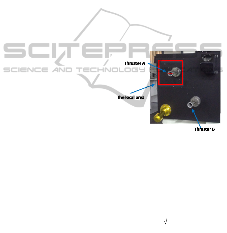
thruster nozzle. The layout of the satellite mockup is
designed including two thrusters and other
accessories.
Because the thruster A is the same as the thruster
B, the thruster to be captured (e.g. thruster A) should
be selected manually at the beginning. When the
vision system is working, the image of the thruster B
disturbs the recognition of the thruster A. So, the
local area around the thruster A is selected. The
local area is a square with sides of length 4 times of
diameter of the thruster A’s circle, as shown in
figure 1.
2.2 Image Edge Extraction
The gray images are then processed by a Canny edge
detector to find the edge binary map (Canny 1986).
The algorithm of the Canny edge detector can be
described as follows.
Figure 1: The local area around the radius of the thruster A.
Firstly, because the Canny edge detector is
susceptible to noise in raw unprocessed image data,
it uses a filter based on a Gaussian curve, where the
raw image is convolved with a Gaussian filter. The
result is a slightly blurred version of the original
which is not affected by a single noisy pixel to any
significant degree.
Secondly, the edge detection operator returns a
value for the first derivative in the horizontal
direction (Gx) and the vertical direction (Gy). From
this the edge gradient and direction can be
determined:
22
tan( )
xy
y
x
GGG
G
a
G
Where G is the edge gradient and
is the
direction angle from the arctangent function with
two arguments. The edge direction angle is rounded
ICINCO2014-11thInternationalConferenceonInformaticsinControl,AutomationandRobotics
334
to one of four angles representing vertical,
horizontal and the two diagonals (i.e. 0, 45, 90 and
135 degrees).
Thirdly, given estimates of the image gradients, a
search is carried out to determine if the gradient
magnitude assumes a local maximum in the gradient
direction. Edges give rise to ridges in the gradient
magnitude image. The algorithm then tracks along
the top of these ridges and sets to zero all pixels that
are not actually on the ridge top so as to give a thin
line in the output. The tracking process exhibits
hysteresis controlled by two thresholds: T1 and T2,
where T1 = 100 and T2 = 200. Then the edge binary
map can be obtained.
2.3 Image Circle Feature Recognition
The input of this subsystem is the edge binary map
of the image acquired by the cameras. Next, the
circles on the image are extracted using the Hough
Transform algorithm. The Hough Transform is a
means of cateloging the components of the edge
image. A contour extraction algorithm is used to
extract the circles and locate a circle with a
maximum diameter in the image representing a
thruster nozzle.
2.4 Curve Fitting
From the section 2.3, we have detected a circle in
images of the left and right camera respectively, that
is circle L and circle R. The detected circle L and
circle R are not “real circles”, are ellipses in fact.
Thus, we use an ellipse fitting algorithm to fit the
circles acquired by two cameras (Chen 2007). Then,
we calculate the coordinates of the origins of the two
ellipses with respect to the image frame.
2.5 Position Calculation
The input of the position calculation system is the
coordinates of projected pixel points of the origins
of the ellipses. The two pixel points with respect to
the image frame are corresponding to the center of
the ellipse with respect to the camera frame. Thus,
the geometry of the two cameras and the method are
used to calculate the center of the ellipse with
respect to the camera frame (Zhang 1999).
2.6 Target Motion Estimation
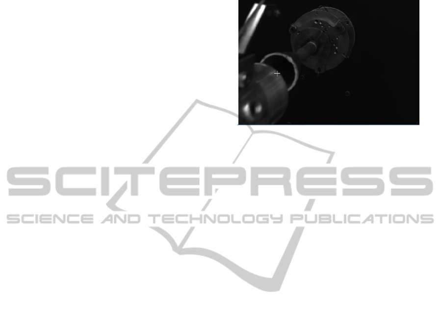
When the robot arm approaches the thruster at a
standoff distance of 0.1 meters, the stereo system
could not shot the images of the thruster as a whole
because the thruster was sheltered by the capture
tool, as shown in figure 2.
Figure 2: The thruster is sheltered by the capture tool.
The target satellite motion is a single-axis rotation
around normal vector of the satellite plane. Thus we
move the robot arm to track the rotating thruster at a
standoff distance of 0.1 meters for 20 seconds to
predict the trajectory of the thruster. Furthermore,
due to the predicted trajectory, we can calculate the
position of the thruster and accomplish the thruster
grappling.
3 EXPERIMENTAL SETUP
The experimental setup, shown in figure 3, consists
of a chaser robotic manipulator along with an end-
effector containing the binocular cameras and the
capture tool. The satellite mockup simulates the
plane of satellites and consists of a 1.5m by 1.5m
base covered with two thrusters and other
accessories. A single-degree turn table moves the
mockup to rotate around the axis of the turn table.
The camera used in this experiment is a Pantera
1M30, with a resolution of 1024 by 1024 pixels and
a maximum frame rate of 30 fps. The cameras are
located at an appropriate angle of 15 degrees with
respect to the capture-tool longitude axis such that
the entire thruster can be viewed by the cameras, as
shown as figure 4.
The algorithm is implemented in Visual C++ and
runs on a desktop with windows XP operating
system equipped with an Intel Core 2Duo processor.
A data logging system saves the images shot by the
binocular cameras.
AVisionSystemforAutonomousSatelliteGrapplewithAttitudeThruster
335
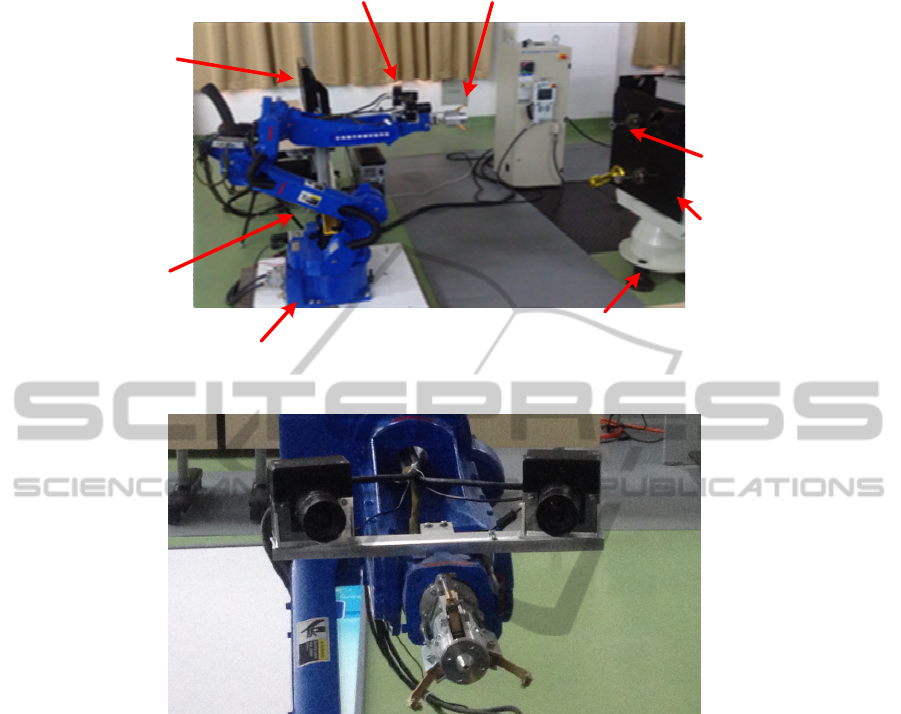
Figure 3: The experimental setup.
Figure 4: The binocular cameras and the capture tool.
4 EXPERIMENTAL RESULTS
4.1 Testing Procedure
In the experiment, one of the two thrusters, of radius
R, was selected manually at the beginning and a
local image square area centred at the selected
thruster is acquired. The robot manipulator keeps
tracking and approaching the selected thruster to a
standoff distance of 0.1 meters. Then, the robot
manipulator keeps this distance of 0.1 meters to the
thruster to predict the trajectory of the thruste. Due
to the predicted trajectory, the end effector continues
to approach the thruster until capturing the thruster.
4.2 Experimental Results
The images shot by the left and right camera are
shown as figure 5. The cross denotes the center of
the recognized thruster. In the course of the
manipulator approaching, the vision system can
recognize the selected thruster and determine its
position at all times. The vision system played an
important role in the grappling control system. The
grappling of the thruster is shown as figure 6.
5 CONCLUSIONS
The binocular vision system are adequate to perform
approaching and grappling procedures on satellite
mockup with attitude thruster as studied in this
work. After selecting the thruster manually, the
vision system can track the target thruster and
determine the position of the thruster continuously.
A future development is the implementation of a
system that reconstructs the shape of the target
Robotma nipulator
Robotbase
Binocularcameras Capturetool
Single‐axisturntabl e
Satellitemockup
Attitudethrushter
Controlcomputer
ICINCO2014-11thInternationalConferenceonInformaticsinControl,AutomationandRobotics
336
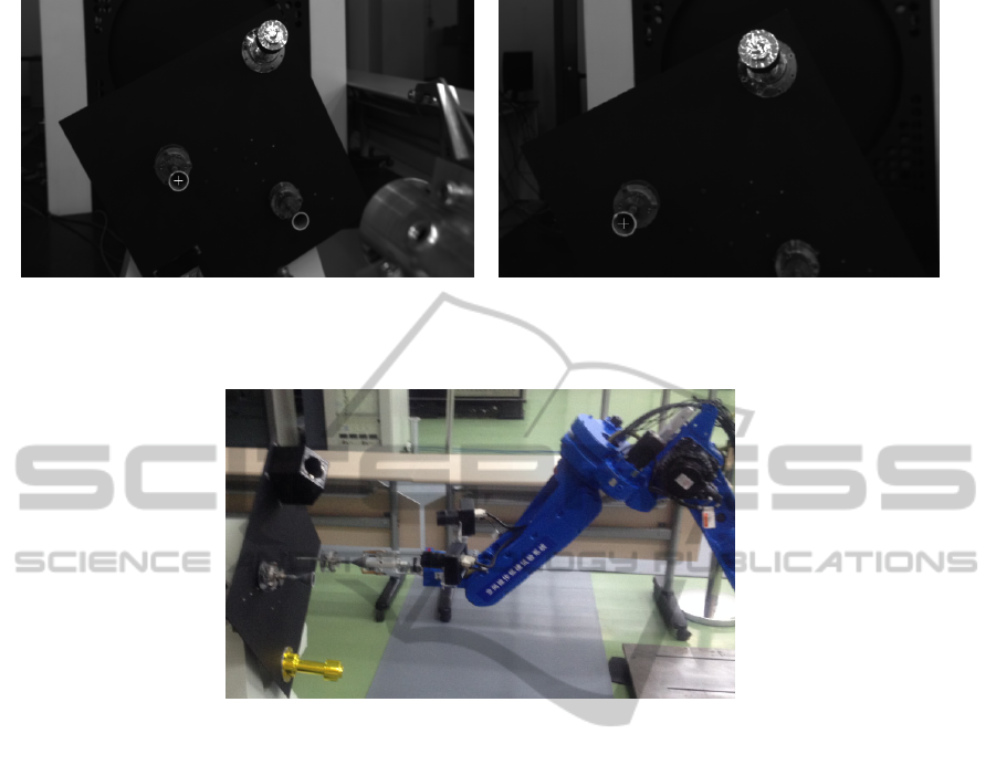
Figure 5: The images shot by left and right cameras at a distance of 1 meter.
(The cross denotes the center of the recognized thruster)
Figure 6: The thruster is grappled by the capture tool with the help of the vision system.
satellite and recognizes the common features (e.g.
interface rings, thrusters, solar panels and etc.) from
this shape.
REFERENCES
Leinz, M. R., Chen, C. T., 2008. Orbital Express
Autonomous Rendezvous and Capture Sensor System
(ARCSS) Flight Test Results, Proc. of SPIE.
Debus, T. J., Dougherty, S. P, 2009. Overview and
Performance of the Front-End Robotics Enabling
Near-Term Demonstration (FREND) Robotic Arm,
AIAA Infotech@Aerospace conference.
David, B., Brook, S., 2013. Phoenix Project Status 2013,
AIAA Space 2013 Conference and Exposition,
Canny, J, 1986. A Computational Approach to Edge
Detection. IEEE Transactions on Pattern Analysis and
Machine Intelligence.
Chen, J. W, 2007. Study on Direct Fitting Algorithm of
Ellipse. Geotechnical Investigation & Surveying.
Zhang, Z. Y, 1999. Flexible camera calibration by viewing
a plane from unknown orientations, ICCV99.
AVisionSystemforAutonomousSatelliteGrapplewithAttitudeThruster
337
