
Resource Allocation in GMD and SVD-based MIMO System
Andreas Ahrens
1
, Francisco Cano-Broncano
2
and C´esar Benavente-Peces
2
1
Hochschule Wismar, University of Technology, Business and Design, Philipp-M¨uller-Straße 14, 23966 Wismar, Germany
2
Universidad Polit´ecnica de Madrid, Ctra. Valencia. km. 7, 28031 Madrid, Spain
Keywords:
Multiple-input Multiple-output System, Singular-value Decomposition, Geometric Mean Decomposition, Bit
Allocation, Power Allocation, Antennas Correlation, Wireless Transmission, Tomlinson-harashima Precoding.
Abstract:
Singular-value decomposition (SVD)-based multiple-input multiple output (MIMO) systems, where the whole
MIMO channel is decomposed into a number of unequally weighted single-input single-output (SISO) chan-
nels, have attracted a lot of attention in the wireless community. The unequal weighting of the SISO channels
has led to intensive research on bit- and power allocation even in MIMO channel situation with poor scattering
conditions identified as the antennas correlation effect. In this situation, the unequal weighting of the SISO
channels becomes even much stronger. In comparison to the SVD-assisted MIMO transmission, geometric
mean decomposition (GMD)-based MIMO systems are able to compensate the drawback of weighted SISO
channels when using SVD, where the decomposition result is nearly independent of the antennas correlation
effect. The remaining interferences after the GMD-based signal processing can be easily removed by using
dirty paper precoding as demonstrated in this work. Our results show that GMD-based MIMO transmission
has the potential to significantly simplify the bit and power loading processes and outperforms the SVD-based
MIMO transmission as long as the same QAM-constellation size is used on all equally-weighted SISO chan-
nels.
1 INTRODUCTION
The strategy of placing multiple antennas at the trans-
mitter and receiver sides, well-known as multiple-
input multiple-output (MIMO) system, improves the
performance of wireless systems by the use of the spa-
tial characteristics of the channel (Zheng, 2003; Yang
et al., 2011). MIMO systems have become the subject
of intensive research over the past 20 years as MIMO
is able to support higher data rates and shows a higher
reliability than single-input single-output (SISO) sys-
tems (Jiang et al., 2008).
Singular-value decomposition (SVD) is well-
established in MIMO signal processing where the
whole MIMO channel is transferred into a number
of weighted SISO channels. The unequal weight-
ing of the SISO channels has led to intensive re-
search to reduce the complexity of the required bit-
and power-allocation techniques (Zanella and Chiani,
2012; Cano-Broncano et al., 2014) in rich and poor
scattering conditions.
However,due to poor scattering conditions the un-
equal weighting of the SISO channels is strongly af-
fected by the antennas correlation effect (Benavente-
Peces et al., 2013; Chiani et al., 2003; Abdi and
Kaveh, 2002; Loyka and Tsoulos, 2002; Shiu et al.,
1998), which makes the process of bit- and power-
allocation more challenging.
The geometric mean decomposition (GMD) is a
signal processing technique which decomposes the
MIMO channel matrix in a different way (Jiang et al.,
2005). Compared to the SVD-assisted MIMO trans-
mission, GMD-based MIMO systems are able to
compensate the drawback of weighted SISO channel
when using SVD independently of the antennas cor-
relation effect. By using the GMD, the whole MIMO
system can be decomposed into a number of equally-
weighted SISO channels, which significantly simpli-
fies the process of bit-and power loading as long as the
same QAM constellation sizes are used on all SISO
channels. The remaining inter-antennas interferences
as a result of the GMD-based signal processing can
be easily removed by using dirty paper precoding, as
demonstrated in this work.
The novelty of our contribution is that we demon-
strate the benefits of amalgamating a suitable choice
of activated MIMO layers and number of bits per sub-
carrier along with the appropriate allocation of the
transmit power under the constraint of a given fixed
27
Ahrens A., Cano-Broncano F. and Benavente-Peces C..
Resource Allocation in GMD and SVD-based MIMO System.
DOI: 10.5220/0005020300270035
In Proceedings of the 11th International Conference on Wireless Information Networks and Systems (WINSYS-2014), pages 27-35
ISBN: 978-989-758-047-5
Copyright
c
2014 SCITEPRESS (Science and Technology Publications, Lda.)

data throughput. Here, optimal and suboptimal bit-
and power-loading in both SVD- and GMD-based
MIMO transmission systems with and without an-
tenna correlation are elaborated. Assuming a fixed
data rate, which is required in many applications (e.g.,
real time video applications), a two stage optimiza-
tion process is proposed. Firstly, the allocation of
bits to the number of SISO channels is optimized and
secondly, the allocation of the available total trans-
mit power is studied when minimizing the overall
bit-error rate (BER) at a fixed data rate. Whereas
optimal power allocation techniques are highly com-
plex, suboptimal solutions offer a good compromise
between complexity and performance lost compared
with optimal solutions. Our results show that GMD-
based MIMO transmission has the potential to signif-
icantly simplify the process of bit and power loading
both in correlated and uncorrelated MIMO systems
and outperforms SVD-based MIMO transmission as
long as the same QAM-constellation size is used on
all equally weighted SISO channels.
The remaining part of this paper is structured
as follows: Section 2 introduces the MIMO system
model and the signal processing techniques used in
this work. In section 3 the well-know quality criteria
is briefly reviewed and applied to our problem. The
proposed resource allocation solutions are discussed
in section 4, while the associated performance results
are presented and interpreted in section 5. Finally,
section 6 provides some concluding remarks.
2 MIMO SYSTEM MODEL
A frequency non-selective MIMO communication
link with n
T
antennas in transmission and n
R
in re-
ception can be described as
u = H·c+ n , (1)
where u corresponds to the (n
R
×1) received data
vector, H is the (n
R
×n
T
) channel matrix, c is the
(n
T
×1) transmitted data vector and n is the (n
R
×1)
Additive White Gaussian Noise (AWGN) vector. Fur-
thermore, it is assumed that the coefficients of the
channel matrix H are independent and identically
Rayleigh distributed with equal variance and that the
number of transmit antennas equals the number of re-
ceive antennas n
T
= n
R
.
In MIMO systems, inter-antennas interferences
appear due to the increased number of antennas and
the consequent multipath signals. These interfer-
ences are described by the off-diagonal elements of
the channel matrix H. In order to avoid the inter-
antenna interferences, appropriate signal processing
techniques are required. The Singular Value Decom-
position (SVD) is used to transform the MIMO chan-
nel into independent layers. Given the channel matrix
H, the application of the SVD to H allows express-
ing it as H = S ·V · D
H
, where the (n
R
× n
R
) ma-
trix S and the (n
T
×n
T
) matrix D
H
are unitary ma-
trices, and V is a real-valued diagonal matrix con-
taining the positive square roots of the eigenvalues of
the matrix H
H
H sorted in descending order, and (·)
H
denotes the Hermitian transpose. Assuming perfect
channel state information (PCSI) is available at both
the transmit and receive sides, the application of pre-
and post-processing decomposes the MIMO channel
into multiple independent SISO layers with different
gains given by the singular values in V, consequently,
the overall transmission relationship results in
y = S
H
·u = S
H
(H·c+ n) = S
H
(H·D·x+ n) (2)
which leads to
y = V·x+ w , (3)
where x is the (n
T
×1) pre-processed transmit data
vector, y is the (n
R
×1) post-processed receive data
vector and the (n
R
×1) post-processed noise vector
is given by w = S
H
·n. The number of independent
SISO layers is limited by min(n
R
,n
T
).
On the other hand, GMD decomposes the channel
matrix into
H = Q·Σ·P
H
, (4)
where the (n
R
×n
R
) matrix Q and the (n
T
×n
T
)
matrix P are composed of orthogonal columns, and
Σ is a real upper triangular matrix where the off-
diagonal elements represent the remaining interfer-
ences and all the elements in the main diagonal take
the same value which is the geometric mean of the
positive square roots of the eigenvalues of the matrix
H
H
H given by
r
ii
=
L
∏
i=1
q
ξ
(i)
!
1
/L
, (5)
where the parameters
p
ξ
(i)
> 0 (for i =
1,2,...,L) are the singular values of H and L defines
the number of activated MIMO layers.
When applying the proposed GMD scheme, the
MIMO system requires appropriate pre- and post-
processing in order to decompose the MIMO system
into multiple SISO channels and the transmission sys-
tem results in
y = Q
H
·u = Q
H
(H·c+n) = Q
H
(H·P·x+ n) , (6)
WINSYS2014-InternationalConferenceonWirelessInformationNetworksandSystems
28
0
0.5
1
1.5
2
2.5
0
0.5
1
1.5
2
2.5
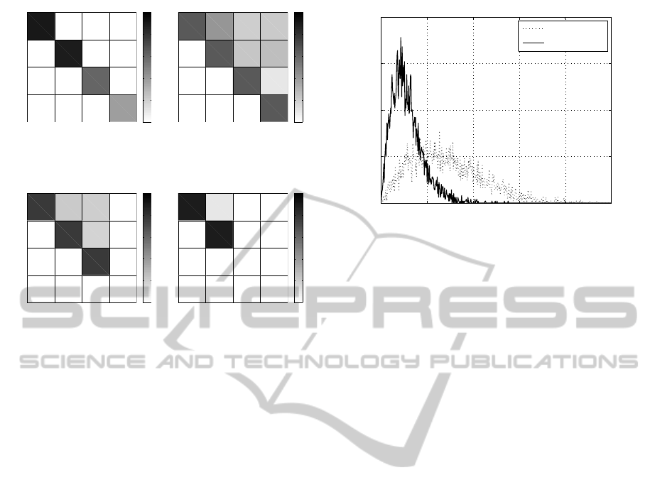
Figure 1: Graphical representation of the matrix V (left) and
the matrix Σ (right).
0
0.5
1
1.5
2
2.5
0
0.5
1
1.5
2
2.5
Figure 2: Graphical representation of the matrix Σ with L =
3 (left) and L = 2 activated layers (right).
and can be represented as
y = Σ ·x+ w (7)
where x is the (n
T
×1) pre-processed transmit data
vector, y is the (n
R
×1) post-processed data vector at
the receiver side and w = Q
H
·n is the (n
R
×1) post-
processed noise vector.
The required signal processing in both SVD- and
GMD-based MIMO transmission systems modifies
neither the transmit power nor the noise levels since
the pre- and post-processing matrices are unitary.
Fig. 1 compares the distribution of the singular
values of the matrix V and the geometric mean of
the singular values of the matrix Σ. The analysis of
Fig. 1 highlights the unequal weighting in the SVD-
based MIMO system (left) and the equal weighting as
well as the remaining inter-antennas interferences in
the GMD-based MIMO system (right). Fig. 2 shows
a representation of the matrix Σ for a different number
of activated layers.
The proximity between the antennas introduces
correlation effect which drops the MIMO system per-
formance. Transmit-side antennas correlation de-
scribes the similitude between the paths correspond-
ing to a pair of antennas (at the transmitter side) with
respect to a reference antenna (at the receiver side).
The antennas’ correlation affects the singular values
distribution and increases the probability of having
predominant layers. The appearance of predominant
weak and strong layers with small and large singular
values respectively increases the BER.
To analyse the correlation effect, the ratio ϑ
0 0.1 0.2 0.3 0.4 0.5
0
0.005
0.01
0.015
0.02
uncorrelated
correlated
pdf →
ϑ →
Figure 3: PDF of the ratio ϑ between the smallest and the
largest singular value for uncorrelated (dotted line) as well
as correlated (solid line) frequency non-selective (4 ×4)
MIMO channel.
between the smallest and the largest singular val-
ues seems to be an unique indicator of the unequal
weighting of the MIMO layers. Fig. 3 shows the prob-
ability density function (PDF) of the ϑ for uncorre-
lated and correlated frequency non-selective (4×4)
MIMO systems. Fig. 3 illustrates how the ratio be-
tween the singular values increases (i.e the unequal
weighting) as the correlation does. This means that
the ratio between the largest and the smallest singu-
lar value increases, and then, the probability of hav-
ing predominant layers increases. In consequence,
the probability of having weak layers with layer poor
behaviour increases and transmit-to-receive antenna
paths become similar affecting the channel behaviour
by decreasing the channel capacity and increasing
the overall BER in the wireless communication link.
As a result, the use of resource allocation techniques
seems an appropriate solution to optimize the layer
behaviour since no power should be allocated to the
MIMO layer having the smallest singular values be-
cause of the overall performance would be deterio-
rated.
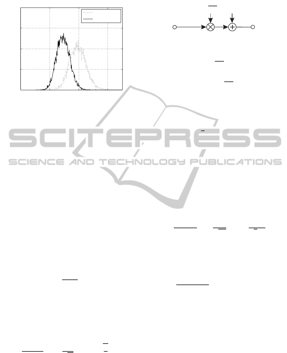
Fig. 4 shows a comparison between the PDF of the
geometric mean of the singular values of the matrix
Σ for uncorrelated and correlated (4×4) MIMO sys-
tems. The analysis of the PDF reveals the decreasing
probability of having larger values of the geometric
mean in the correlated GMD-based MIMO systems
compared to the uncorrelated ones. As an example,
analysing the PDF curves for a fixed ϑ = 2, the prob-
ability of the geometric mean of the singular values
in the uncorrelated GMD-based MIMO channel takes
10 times (approximately) larger than in the correlated
one. This means that increasing the correlation, the
probability of having larger values decreases and con-
ResourceAllocationinGMDandSVD-basedMIMOSystem
29
0 1 2 3
0
0.005
0.01
0.015
0.02
uncorrelated
correlated
pdf →
singularvalues →
Figure 4: PDF of the geometric mean of the singular values
of the matrix Σ without correlation (dotted line) and with
correlation (solid line) when using L = 3 activated layers.
sequently, the MIMO performance drops. Further
comparisons between the BER performance of the
SVD-based and the GMD-based MIMO systems are
accomplished in following sections.
3 QUALITY CRITERIA
The quality criteria considered for end-to-end wire-
less communication system performance is given in
terms of the bit-error-rate (BER), which quantifies the
reliability of the entire wireless system from input to
output.
In order to optimize the overall channel perfor-
mance the argument of the complementary error func-
tion, also known as signal-to-noise ratio (SNR), is
maximized as an alternative to minimizing the BER.
The SNR per quadrature component is defined by
ρ =
(U
A
)
2
(U
R
)
2
, (8)
where U
A
is the half vertical eye opening and U
2
R
is the noise power per quadrature component taken
at the detector input. The relationship between the
signal-to-noise ratio ρ and the bit-error probability
evaluated for AWGN channels and M-ary Quadrature
Amplitude Modulation (QAM) is given by
P
b
=
2
log
2
(M)
·
1−
1
√
M
·erfc
r
ρ
2
. (9)
The application of the SVD pre- and post-
processing leads to an unequally weighted SISO
channel (see Fig. 5) with different eye openings per
activated MIMO layer ℓ and per transmitted symbol
block k according to
x
ℓ,k
y
ℓ,k
w
ℓ,k
p
ξ
ℓ,k
Figure 5: System model per MIMO layer ℓ and transmitted
data block k after SVD pre- and post-processing.
U
(ℓ,k)
A
=
q
ξ
ℓ,k
·U
s ℓ
, (10)
where U
sℓ
denotes the half-level transmit amplitude
assuming M
ℓ
-ary QAM and
p
ξ
ℓ,k
represents the pos-
itive square roots of the eigenvalues of the matrix
H
H
H. Considering QAM constellations, the aver-
age transmit power per MIMO layer P
s ℓ
may be ex-
pressed as
P
s ℓ
=
2
3
U
2
s ℓ
(M
ℓ
−1) . (11)
By taking L ≤ min(n
T
,n
R
) MIMO activated lay-
ers into account, the overall transmit power results in
P
s
=
L
∑
ℓ=1
P
s ℓ
. (12)
where P
s
is the total available power at the trans-
mit side. The layer-specific bit-error probability at the
time slot k is obtained by combining (8), (9), and (10)
resulting in
P
(ℓ,k)
b
=
2
log
2
(M
ℓ
)
1−
1
√
M
ℓ
erfc
U
(ℓ,k)
A
√
2U
R
!
.
(13)
The aggregate bit-error probability at the time slot
k, taking L activated MIMO-layers into account, re-
sults in
P
(k)
b
=
1
L
∑
ν=1
log
2
(M
ν
)
L
∑
ℓ=1
log
2
(M
ℓ
)P
(ℓ,k)
b
. (14)
Finally, the BER of the whole MIMO system is
obtained by considering the different transmission
block SNRs. In order to balance the bit error probabil-
ity along the MIMO system activated layers, bit and
power loading provides helpful strategies to improve
the overall performance. The bit error probability at
a given time k is influenced by both the chosen QAM
constellation and the layer-specific weighting factors.
In particular, the layer-specific weighting factors in-
fluence the overall performance.
WINSYS2014-InternationalConferenceonWirelessInformationNetworksandSystems
30

Table 1: Investigated QAM transmission modes assuming
n
R
= n
T
= 4.
throughput layer 1 layer 2 layer 3 layer 4
8 bit/s/Hz 256 0 0 0
8 bit/s/Hz 64 4 0 0
8 bit/s/Hz 16 16 0 0
8 bit/s/Hz 16 4 4 0
8 bit/s/Hz 4 4 4 4
x
ℓ,k
y
ℓ,k
w
ℓ,k
p
ξ
ℓ,k
√
p
ℓ,k
Figure 6: Resulting layer-specific system model including
MIMO-layer PA.
4 RESOURCE ALLOCATION
Resource allocation strategies allow the optimization
of the MIMO channel overall performance. Hence,
the BER can be minimized under the constraints of a
fixed data rate and a limited available transmit power.
Regarding the channel quality, the BER performance
is affected by both the layer-specific weighting factors
p
ξ
ℓ,k
and the QAM-constellation size M
ℓ
. Assuming
a fixed data rate, regardless of the channel quality, Ta-
ble 1 highlights the resulting layer-specific QAM con-
stellations for a fixed spectral efficiency of 8 bit/s/Hz.
Following the allocation of bits per layer, power allo-
cation (PA) can be added to optimize the overall BER.
The layer-specific power allocation weights
√
p
ℓ,k
ad-
just the half-vertical eye opening per symbol block as
follows (see Fig. 6)
U
(ℓ,k)
APA
=
√
p
ℓ,k
·
q
ξ
ℓ,k
·U
sℓ
. (15)
This results in the layer-specific transmit power per
symbol block k
P
(ℓ,k)
s PA
= p
ℓ,k
·P
sℓ
, (16)
where P
sℓ
denotes the allocated power per MIMO
layer without PA e.g. P
sℓ
= P
s
/L. Therein the param-
eter L describes the number of activated MIMO lay-
ers. Taking all activated MIMO layers L into account,
being L ≤min(n
T
,n
R
), the overall transmit power per
symbol block k is obtained as
P
(k)
s PA
=
L
∑
ℓ=1
P
(ℓ,k)
sPA
. (17)
With (15) the layer-specific bit-error probability at
the time k changed to
Table 2: Investigated channel profiles for studying the effect
of optimum power allocation.
Profile layer 1 layer 2 layer 3 layer 4
CM-1 1,7500 0,8750 0,4375 0,2188
CM-2 1,9000 0,6333 0,2111 0,0704
P
(ℓ,k)
bPA
=
2
log
2
(M
ℓ
)
1−
1
√
M
ℓ
erfc
U
(ℓ,k)
APA
√
2U
R
!
.
(18)
In order to find the optimal set of PA parameters
minimizing the overall BER, i. e.,
√
p
ℓ,k
, the Lagrange
multiplier method is used. The cost function for this
method J(p
1,k
, p
2,k
,..., p
L,k
) may be expressed as
J(···) =
1
L
∑
ν=1
log
2
(M
ν
)
L
∑
ℓ=1
log
2
(M
ℓ
)P
(ℓ,k)
b
+ λ ·B ,
(19)
where λ denotes the Lagrange multiplier. The pa-
rameter B in (19) describes the boundary condition to
meet the overall transmit power constraints
B =
L
∑
ℓ=1
P
sℓ
−P
(ℓ,k)
sPA
= 0 (20)
=
L
∑
ℓ=1
P
sℓ
(1− p
ℓ,k
) = 0 . (21)
Assuming P
sℓ
= P
s
/L, the boundary condition re-
sults in
B =
P
s
L
L
∑
ℓ=1
(1− p
ℓ,k
) = 0 . (22)
Given (22), the transmit power coefficients
have to fulfill the following equation
∑
L
ℓ=1
p
ℓ,k
=
L. Differentiating the Lagrangian cost function
J(p
1,k
, p
2,k
,..., p
L,k
) with respect to the p
ℓ,k
and set-
ting it to zero, leads to the optimal set of PA parame-
ters.
In order to analyse the effect of PA thoroughly,
the fixed channel profiles shown in Table 2 are inves-
tigated. For comparison reasons, the channel profile
CM-1 describes a MIMO channel with a low degree
of correlation (ϑ = 0,125) whereas the channel CM-
2 introduces a higher degree of antennas’ correlation
(ϑ = 0,037). In this case the unequal weighting of
the layers becomes stronger compared to the channel
profile CM-1.
Since the optimal PA solution is notably computa-
tionally complex to implement, a suboptimal solution
ResourceAllocationinGMDandSVD-basedMIMOSystem
31
which concentrates on the argument of the comple-
mentary error function is investigated. In this particu-
lar case the signal-to-noise ratio
ρ
(ℓ,k)
PA
=
U
(ℓ,k)
A PA
2
U
2
R
(23)
is assumed to be equal for all activated MIMO
layers per data block k,i. e.,ρ
(ℓ,k)
PA
= constant ℓ =
1,2,...,L.
Assuming that the transmit power coefficient per
layer is uniformly distributed, the power to be allo-
cated to each activated MIMO layer ℓ and transmitted
data block k can be simplified as follows:
p
ℓ,k
=
(M
ℓ
−1)
ξ
ℓ,k
·
L
L
∑
ν=1
(M
ν
−1)
ξ
ν,k
. (24)
Hence, for each symbol the same half vertical eye
opening of (15) can be guaranteed (ℓ = 1,...,L), i. e.,
U
(ℓ,k)
A PA
= constant ℓ = 1,2,...,L . (25)
Considering an identical noise power at the de-
tector’s input, the above-mentioned equal quality sce-
nario is encountered.
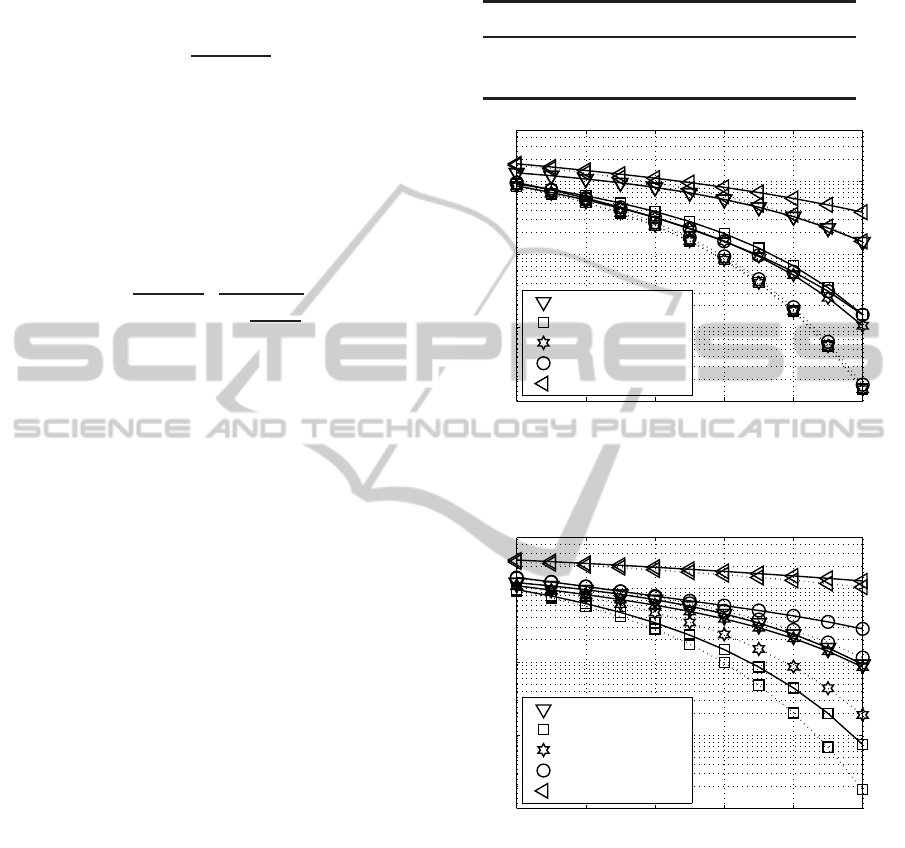
The BER curves for channel profiles CM-1 and
CM-2 are shown in Fig. 7 and Fig. 8. In order to use
the MIMO channel in an optimized way not all the
MIMO layers should be necessarily activated. Fur-
thermore, PA in combination with an appropriate se-
lection of number of activated MIMO layers guaran-
tees the best BER performance when transmitting at a
fixed data rate of with spectral efficiency 8 bit/s/Hz.
In Fig. 9 the obtained BER curves with the opti-
mal PA based on the Lagrange multiplier method are
shown considering the above mentioned equal qual-
ity criteria. As demonstrated by computer simulations
the loss in the overall BER with the equal quality cri-
teria is quite acceptable when using the optimized bit
loading.
Table 3 compares the memory usage and CPU
time required to execute the optimal and suboptimal
solutions with a processor AMD A4−5300 APU at
3.40Ghz. It turned out that the proposed suboptimal
equal-SNR PA technique presents a lower complexity
and computational load than the optimal one.
Fig. 10 shows a comparison of the BER curves
among the QAM transmission modes listed in Ta-
ble 1 with and without PA when transmitting 8
bit/s/Hz over uncorrelated frequency non-selective
MIMO channels. It can be seen that not all MIMO
layers should be activated in correlated as well as in
uncorrelated MIMO channels to minimize the overall
BER while transmitting at a fixed date rate.
Table 3: Investigated PA methods for comparing the
computational load assuming a (4 ×4) MIMO system at
10 log
10
(E
s
/N
0
) = 20 dB.
Power Allocation Memory Time
Optimal 9.80 MiB 200.00 ms
Suboptimal 0.22 MiB 5.00 ms
10 12 14 16 18 20
10
−4
10
−3
10
−2
10
−1
10 ·lg(E
s
/N
0
) (in dB) →
bit-error rate →
(256,0,0,0) QAM
(64,4,0,0) QAM
(16,16,0,0) QAM
(16,4,4,0) QAM
(4,4,4, 4) QAM
Figure 7: BER with optimal PA(dotted line) and without PA
(solid line) when using the transmission modes introduced
in Table 1 and transmitting 8 bit/s/Hz over channel CM-1.
10 12 14 16 18 20
10
−4
10
−3
10
−2
10
−1
10 ·lg(E
s
/N
0
) (in dB) →
bit-error rate →
(256,0,0,0) QAM
(64,4,0,0) QAM
(16,16,0,0) QAM
(16,4,4,0) QAM
(4,4,4, 4) QAM
Figure 8: BER with optimal PA(dotted line) and without PA
(solid line) when using the transmission modes introduced
in Table 1 and transmitting 8 bit/s/Hz over channel CM-2.
5 RESULTS
In this section the computer simulation results con-
cerning the analysis of the SVD-based and the GMD-
based MIMO systems are shown. These results high-
light the bit- and power-allocation strategies which
obtain the best performance. Furthermore, the best
results are compared when using the SVD-based and
GMD-based systems.
WINSYS2014-InternationalConferenceonWirelessInformationNetworksandSystems
32
10 12 14 16 18 20
10
−3
10
−2
10
−1
10 ·lg(E
s
/N
0
) (in dB) →
bit-error rate →
(16,16,0,0) QAM
(16,4,4,0) QAM
Figure 9: BER with optimal PA (dotted line), equal-SNR
PA (dashed line) and without PA (solid line) when using the
transmission modes introduced in Table 1 and transmitting
8 bit/s/Hz over channel CM-2.
12 14 16 18 20 22 24
10
−8
10
−6
10
−4
10
−2
10 ·lg(E
s
/N
0
) (in dB) →
bit-error rate →
(256,0,0, 0) QAM
(64,4,0, 0) QAM
(16,16,0, 0) QAM
(16,4,4, 0) QAM
(4,4,4,4) QAM
Figure 10: BER with PA (dotted line) and without PA
(solid line) when using the transmission modes introduced
in Table 1 and transmitting 8 bit/s/Hz over uncorrelated fre-
quency non-selective MIMO channels.
The accomplished results show how the selection
of the most favourable QAM transmission mode, the
optimal transmit power allocation per active layer and
time slot as well as the proper mathematical decom-
position achieves the best BER performance.
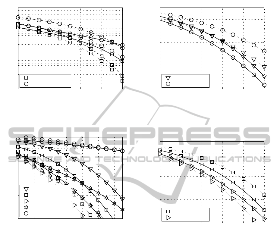
Fig. 11 shows the BER curves of the SVD-based
MIMO system and remarks the poor performance ob-
tained in the presence of correlation. When trans-
mitting the same QAM constellation through the best
two layers, the channel affected by antennas’ correla-
tion performs much worse than the uncorrelated. On
the other hand, when transmitting unequal QAM con-
stellations through the two activated layers, the chan-
nel affected by antennas correlation performs worse
than the uncorrelated, but the performance difference
is not as notably as the case with equal QAM con-
stellations. This means that bit-allocation is specially
10 12 14 16 18 20
10
−8
10
−6
10
−4
10
−2
10 ·lg(E
s
/N
0
) (in dB) →
bit-error rate →
(64,4,0, 0) QAM
(16,16,0, 0) QAM
Figure 11: BER performance with SVD processing and
equal-SNR PA when using the transmission modes intro-
duced in Table 1 and transmitting 8 bit/s/Hz over frequency
non-selective (4 ×4) MIMO channels without correlation
(solid line) and with correlation (dotted line).
10 12 14 16 18 20
10
−8
10
−6
10
−4
10
−2
10 ·lg(E
s
/N
0
) (in dB) →
bit-error rate →
(64,4,0, 0) QAM
(16,16,0, 0) QAM
Figure 12: BER curves with GMD processing (dotted
line) assuming perfect interference cancellation compared
to BER curves with SVD (solid line) when using the trans-
mission modes introduced in the legend with equal-SNR
PA and transmitting 8 bit/s/Hz over frequency non-selective
(4×4) MIMO channels without antenna correlation.
useful in MIMO channels affected by antennas’ cor-
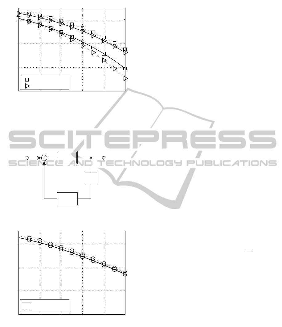
relation. Fig. 12 shows the BER performance of the
GMD-based (4×4) MIMO system (assuming perfect
remaining interference cancellation) compared to the
SVD-based (4×4) MIMO system, both for frequency
non-selective channels. Fig. 13 extends that analy-
sis to the case in which the channels are affected by
antennas correlation. The analysis of Fig. 12 high-
lights that when unequal QAM modes are used on the
two activated layers (consider the transmission mode
analysed), the SVD-based system presents a superior
performance than the GMD-based. This is due to the
unequal performance of the two layers in the SVD-
based MIMO system.
On the other hand, when transmitting equal QAM
ResourceAllocationinGMDandSVD-basedMIMOSystem
33
10 12 14 16 18 20
10
−8
10
−6
10
−4
10
−2
10 ·lg(E
s
/N
0
) (in dB) →
bit-error rate →
(64,4,0, 0) QAM
(16,16,0, 0) QAM
Figure 13: BER curves with GMD technique (dotted line)
assuming perfect interference cancellation compared to
BER curves with SVD (solid line) when using the trans-
mission modes introduced in the legend with equal-SNR
PA and transmitting 8 bit/s/Hz over frequency non-selective
(4×4) MIMO channels with antenna correlation.
-
modulo
H
t
z
−1
x
c
Figure 14: Tomlinson-Harashima precoding model in the
transmission side for MIMO systems.
10 12 14 16 18 20
10
−8
10
−6
10
−4
10
−2
10 ·lg(E
s
/N
0
) (in dB) →
bit-error rate →
Perfect IC
IC using THP
Figure 15: BER comparison between Perfect Interfer-
ence Cancellation and Interference Cancellation using THP
when using the transmission mode (4,4,4, 4) and transmit-
ting 8 bit/s/Hz over uncorrelated frequency non-selective
GMD-based MIMO channels.
modes through the two activated layers, the GMD-
based MIMO system shows the best results, as both
layers present the same performance. These conclu-
sions are reinforced by the results in Fig. 13 for cor-
related channels. In this case, as the performance of
the two activated layers is much more different in the
SVD-based MIMO system, the use of unequal QAM
modes along the activated layers becomes more im-
portant to obtain a better performance. In this case
the SVD-based system shows a superior performance
than the GMD-based. Nevertheless, the results high-
light that the use of equal QAM modes along the acti-
vated layers is much more appropriate for the GMD-
based MIMO system. Then, GMD-based MIMO sys-
tems do not require bit allocation strategies to obtain
the best performance. Nevertheless, SVD-based sys-
tems require bit allocation to improve the channel per-
formance.
In order to eliminate the inter-antennas interfer-
ence and the error propagation in the GMD-based
MIMO systems a Tomlinson-Harashima precoding
(THP) module is proposed at the transmitted side.
Fig. 14 shows the THP system model where x cor-
responds to the (n
T
×1) transmitted vector followed
by a modulo reduction which suppresses the power
enhancement. Assuming perfect channel state infor-
mation is available at the transmitter side, H
t
is given
by
H
t
= Σ −diag(Σ) ·I , (26)
where Σ corresponds with a real upper triangular
matrix, diag(·) are the main diagonal elements and I
is the identity matrix. The modulo operator (Fig. 14)
constraints the real and imaginary part of the trans-
mit symbols into the boundary constellation of width
of the modulo operator. This modulo is defined by
modulo(∆·q) = modulo(2·U
s
·q), where ∆ is the dis-
tance between two adjacent symbols, U
s
denotes the
half-level transmit amplitude and q =
√
M, being M
the modulation index in every active MIMO layer.
In Fig. 15 a comparison between perfect inter-
ference cancellation technique and THP interference
cancellation for a (4,4,4,4) QAM transmission mode
is shown. The results reveal that the GMD-based
MIMO system performance with THP is close to
those obtained when perfect interference cancellation
is assumed. The losses are about 0.5 dB compared
to the perfect cancellation. In consequence the THP
seems to be an appropriate strategy to eliminate the
GMD-based system remaining interference with little
computational complexity overhead.
6 CONCLUSION
This paper has investigated the use of bit- and power-
allocation techniques to improve the performance of
SVD-based as well as GMD-based MIMO systems
WINSYS2014-InternationalConferenceonWirelessInformationNetworksandSystems
34

as demonstrated by the performed analysis and the
shown results. The combination of these techniques
remarkably improves the channel performance, even
when suboptimal algorithms are used where little
losses are produced. Nevertheless, these techniques
include some processing overhead which can be re-
duced by using suboptimal solution with low perfor-
mance losses.
A relevant challenge and achievement of this in-
vestigation is the introduction of the GMD signal pro-
cessing to improve the MIMO channel performance.
The analysis focusses on both uncorrelated and corre-
lated (4×4) MIMO channels and the results are com-
pared with those obtained when using the SVD signal
processing, combined with bit- and power-allocation
techniques.
GMD-based MIMO systems show remaining
inter-antennas interferences. Hence, some additional
signal processing techniques must be applied to re-
move it. The THP has demonstrated to be an appro-
priate technique to remove the interferences with low
losses compared to the perfect interference elimina-
tion case.
According to the obtained results the combination
of GMD-based MIMO systems with the THP shows
a noteworthy BER performance improvement com-
pared to the SVD-based MIMO system. First, assum-
ing the remaining inter-antennas interferences have
been completely removed, the GMD-based MIMO
system shows equal quality SISO channels (layers)
and, in consequence, bit- and power-allocation tech-
niques are not required as they do not improve the
channel performance. Conversely, the performance
drops. This conclusion applies to both antennas un-
correlated and correlated channels. The SVD-based
MIMO channel requires the application of bit- and
power- allocation techniques to improve the perfor-
mance, as it presents unequal quality layers. Second,
when bit allocation is applied to both the SVD-based
and GMD-based MIMO systems, as shown in our
work, the SVD-based one presents a superior perfor-
mance, because in the GMD-based system the advan-
tage of having equal quality layers is not taken when
transmitting data with different QAM constellation
sizes. Finally, the obtained results demonstrate that
the GMD-based MIMO system with remaining inter-
antennas interference cancellation by using the THP
shows a superior performance than the SVD-based
system without requiring bit- and power-allocation
techniques, which notably reduces the computational
complexity and overhead.
REFERENCES
Abdi, A. and Kaveh, M. (2002). A Space-time Correlation
Model for Multielement Antenna Systems in Mobile
Fading Channels. IEEE Journal on Selected Areas in
Communications, 20:550–560.
Benavente-Peces, C., Cano-Broncano, F., Ahrens, A.,
Ortega-Gonzalez, F., and Pardo, J. (2013). Analysis of
Singular Values PDF and CCDF on Receiver-Side An-
tennas Correlated MIMO Channels. Electronics Let-
ters, 49, Issue: 9:625–627.
Cano-Broncano, F., Ahrens, A., and Benavente-Peces, C.
(Lisboa, (Portugal), 7-9 January 2014). Iterative
Bit- and Power Allocation in Correlated MIMO Sys-
tems. In International Conference on Pervasive and
Embedded Computing and Communication Systems
(PECCS).
Chiani, M., Win, M., and Zanella, A. (2003). On the Capac-
ity of Spatially Correlated MIMO Rayleigh-Fading
Channels. IEEE Transactions on Information Theory,
49:2363–2371.
Jiang, Y., Hager, W., and Jian, L. (2008). The Generalized
Triangular Decomposition. Mathematics of Computa-
tion, 77:1037–1056.
Jiang, Y., Li, J., and Hager, W. (2005). Joint Transceiver
Design for MIMO Communications Using Geometric
Mean Decomposition. IEEE Transactions on Signal
Processing, 53:3791–3803.
Loyka, S. and Tsoulos, G. (2002). Estimating MIMO Sys-
tem Performance using the Correlation Matrix Ap-
proach. IEEE Communications Letters, 6:19 – 21.
Shiu, D.-S., G.J, F., Gans, M., and Kahn, J. (1998). Fading
Correlation and its effect on the Capacity of multi-
element Antenna Systems. In Universal Personal
Communications.
Yang, P., Xiao, Y., Yu, Y., and Li, S. (2011). Adaptive
Spatial Modulation for Wireless MIMO Transmission
Systems. IEEE Communications Letters, 15:602–604.
Zanella, A. and Chiani, M. (2012). Reduced Complexity
Power Allocation Strategies for MIMO Systems with
Singular Value Decomposition. IEEE Transactions on
Vehicular Technology, 61:4031–4041.
Zheng, L. (2003). Diversity and Multiplexing: A Funda-
mental Tradeoff in Multiple-Antenna Channels. IEEE
Transactions on Information Theory, 49:1073–1096.
ResourceAllocationinGMDandSVD-basedMIMOSystem
35
