
Hardware-In-the-Loop Radar Test Simulator
Halit Ergezer, M. Furkan Keskin and Osman Gunay
M
˙
IKES, Microwave Electronic Systems Inc., Ankara, Turkey
Keywords:
Radar Simulator, hardware-in-the-loop, Target, Jammer, Clutter
Abstract:
In this work, a real-time hardware-in-the-loop (HIL) radar target and environment simulator (RTSim) is pre-
sented. RTSim is developed to test the radar systems starting from the initial algorithm development until
the final field testing stages. In this way, it is possible to avoid the costly field tests in constantly changing
conditions and test the radar systems in a controlled but highly complex environments. In the real-time oper-
ation scenario, Radar Signal Processing Unit (RSPU) sends the parameters of the radar signal to the RTSim.
For each receive channel, RTSim generates baseband IQ (16-bit I, 16-bit Q) signals using these parameters
and user programmed environment including targets, jammers, atmospheric effects, clutter, and radar related
system noise. The generated baseband signals are sent to RSPU over fiberoptic lines.
1 INTRODUCTION
The need for real-time simulation tools to test radar
systems is increasing in parallel with developments
in radar technology. The algorithms used in RSPUs
should be justified under real environment conditions
prior to the integration with radar hardware. The cost
of real environment tests is very high and it is al-
most impossible to repeat the experiments under the
same conditions. Therefore this necessitates the de-
velopment of a system that simulates the environment
in which radar signals travel, and the targets that the
radar is trying to detect.
Many of the radar target and environment simu-
lators are designed as commercial products and their
implementation details are not disclosed as academic
publications (Utteridge, 1987; Saab Sensis, 2013; In-
tersoft Electronics, 2013; EW Simulation Technol-
ogy, 2013; Technology Service Corporation, 2013).
All of these products are analog simulators that work
in the RF (Radio Frequency) or IF (Intermediate Fre-
quency) band and they are not closed loop systems
which means that they do not receive the radar param-
eters in real-time. Another radar target generator that
uses FPGAs (Field Programmable Gate Arrays) for
baseband signal generation is proposed in (Andraka
and Phelps, 1998). Compared to these products, RT-
Sim is a more flexible digital simulator that generates
phase-coded baseband IQ signals. All parameters of a
radar signal (RF frequency, waveform type, sampling
rate, etc.) can beadjusted by radar for each pulse burst
waveform.
The components of a typical radar, a test environ-
ment and the role of RTSim is shown in Figure 1.
The simulator generates signals whose properties
are determined by the radar signal processing units,
in the form of baseband IQ. The generated signal will
contain all the effects described in the user defined
scenario including; targets, jammers, chaff, decoys,
environment (clutter and propagation effects), anten-
nas, and radar hardware (amplifiers, mixers, etc.).
The generated IQ signal is sent to the RSPUs over
fiberoptic lines. In that sense RTSim provides a
hardware-in-the-loop test environment that can ac-
count for all the effects that a radar signal encounters
until it is received by the RSPUs.
2 COMPONENTS OF RTSIM
RTSim consists of a control PC, embedded processors
and FPGA (Field Programmable Gate Array) hard-
ware as shown in Figure 2. Control PC has the sim-
ulation engine and user interfaces. Simulation engine
calculates the navigation and orientation parameters
of radar and target platforms in real-time. It uses Dig-
ital Terrain Elevation Data (DTED) maps for terrain
visualization. All radar and target parameters can be
adjusted from the user interfaces.
Target parameters include:
• Position, velocity, route,
666
Ergezer H., Keskin M. and Gunay O..
Hardware-In-the-Loop Radar Test Simulator.
DOI: 10.5220/0005034506660673
In Proceedings of the 4th International Conference on Simulation and Modeling Methodologies, Technologies and Applications (SIMULTECH-2014),
pages 666-673
ISBN: 978-989-758-038-3
Copyright
c
2014 SCITEPRESS (Science and Technology Publications, Lda.)
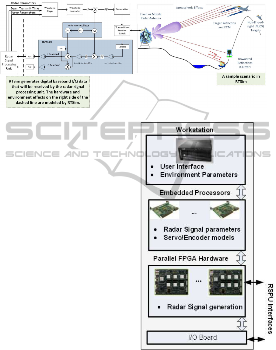
Figure 1: RTSim and radar environment.
• Scatter position and RCS (Radar cross section)
parameters,
• RCS type (constant, orientation/frequency depen-
dent),
• Multipath parameters,
• Scintillation parameters (swerling type and corre-
lation time),
• Jammer parameters (noise jammer, deceptive
jammer, activation time, etc.),
• Jet engine modulation, helicopter blade modula-
tion.
Radar parameters include:
• Transmitted power, maximum range,
• Antenna scan pattern (circular or RSPU con-
trolled),
• Antenna pattern tables,
• Waveform tables (for phase-coded signals),
• Pulse-repetition-interval (PRI) tables.
Environment parameters that can be programmed
from the user interface are: statistical clutter model
(distribution type, parameters), atmospheric attenua-
tion and rain attenuation.
Simulation parameters that are adjusted in the user
interface are sent to the embedded processors and FP-
GAs before the simulation starts. Radar and target
platforms’ navigation information is sent to the em-
bedded processors in real-time. Embedded processors
also receive radar beam parameters from RSPUs. The
beam message defines the parameters of the radar sig-
nal that RTSim generates:
• RF frequency and sampling rate,
• Antenna pattern table ID,
Figure 2: RTSim and radar environment.
• Waveform table ID,
Hardware-In-the-LoopRadarTestSimulator
667
• Pulse Width (PW) and Pulse-repetition-interval
(PRI),
• PRI table ID,
• Antenna orientation.
When the beam message is received embedded
processors calculate the parameters that FPGAs use
for signal generation. Parameters defined in time units
(PW, PRI, delay, etc.) are converted to FPGA clock
units. Doppler calculations are performed for each
platform. Channel attenuations for each platform,
jammers and clutter are calculated and sent to the FP-
GAs. Servo and encoder model calculations are also
performed by embedded processors to determine the
orientation of the radar antenna. Encoder model con-
trols the fixed speed circular motion of the antenna,
whereas servo model is for the RSPU controlled mo-
tion of the antenna.
FPGAs generate the radar signals using the pa-
rameters sent by the embedded processors. Radar
signal generator, receiver channels, clutter distribu-
tion generators, system noise generator, jammer noise
generators are all implemented in the FPGAs.
3 RTSIM MODELS
3.1 Target Modeling
Radar target generation approaches in the literature
has focused on statistical modeling of target RCS.
Jet Engine Modulation (JEM) and Helicopter Blade
Modulation (HBM) effects are also studied for mov-
ing target identification (Sandhu and Saylor, 1985;
Carriere and Moses, 1988; Bell and Grubbs, 1993;
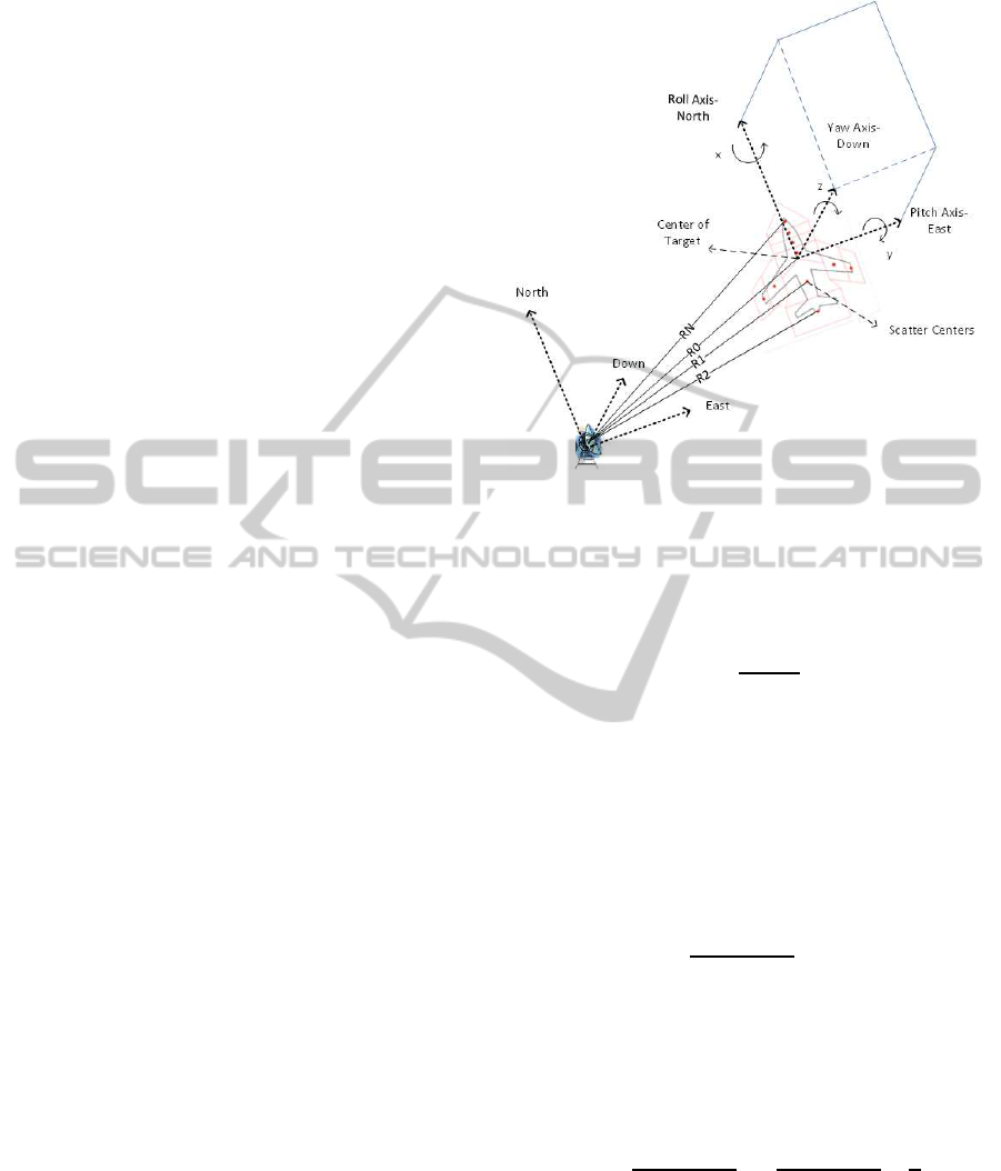
Phu et al., 1995). In RTSim, targets are modeled
as independent multiple scatters with different dy-
namic RCS tables. When the orientation of the tar-
get changes, the relative position of each scatter with
respect to the radar changes.
Dynamic RCS of targets is modeled by using the
RCS value that corresponds to the orientation (yaw,
pitch, roll) of the target. JEM and HBM are mod-
eled using correlated complex Gaussian distributed
signals. Target scintillation is modeled by four Swer-
ling models (Richards, 2005). Doppler effect is mod-
eled by adding an additional doppler phase value to
the phase codes of the radar signals at each clock cy-
cle of the FPGA.
Doppler speed, which is the velocity component
of the target in the direction of the radar, can be cal-
culated as follows:
V
D
= V
x
cos(φ)cos(θ)
+ V
y
sin(φ)cos(θ) +V
z
sin(θ) (1)
Figure 3: Multiple scatter modeling.
where φ is the azimuth and θ is the elevation angle
between radar and the target. Doppler frequency is
calculated using RF frequency (f) and speed of light
(c) :
f
D
=
2f|V
D
|
c
(2)
The doppler phase value should be incremented
at specified intervals that depend on the doppler fre-
quency, to give the doppler effect. The doppler phase
is incremented by a specific amount at specific inter-
vals. The interval and increment values and the sign
of the velocity are sent to the FPGA as doppler pa-
rameters for each beam message. The interval is cal-
culated as the number of FPGA clock cycles:
p
c
=
f
s
× k
f
D
(2
nb
− 1)
+ 0.5
(3)
where f
s
is the sampling frequency, k is the in-
crement value, nb is the number of bits of the phase
codes. The value of k that gives the best frequency
resolution is determined by the following optimiza-
tion:
k = argmin
x
f
s
× x
f
D
(2
nb
− 1)
−
f
s
× x
f
D
(2
nb
− 1)
+
1
2
(4)
where x = 1,. .., 100.
Multipath effects are also modeled in RTSim.
Three multipaths can be used for each target platform.
Multipaths are modeled in the same way as the targets
but they have different complex attenuation constants
that depend on reflection angle, radar frequency and
the reflection surface (Skolnik, 2008).
SIMULTECH2014-4thInternationalConferenceonSimulationandModelingMethodologies,Technologiesand
Applications
668

Figure 4: Multipaths.
For each receiverchannel the received power from
a target platform is calculated as follows:
P
r
=
P
t
|K
1
|
2
|K
2
|
2
λ
2
σ
(4π)
3
R
4
d
L
s
(5)
where P
t
is the transmitted power, K
1
, K
2
are transmit
and receive antenna gains, λ is the wavelength, σ is
the RCS, R
d
is the distance between radar and target,
and L
s
denotes the losses (polarization, atmospheric,
rain). Using the received power the channel attenua-
tion is calculated as follows:
C
A
= e
− j4πR
d
/λ
× e
j(∠K
1
+∠K
2
)
×
s
P
r
D
P
r
× D
SG
(6)
where D
P
r
is the default received power that corre-
sponds to the quantized signal amplitude D
SG
. These
two parameters are used to adjust the dynamic range
of the 16-bit baseband IQ signal.
3.2 Jammer Modeling
The purpose of electronic warfare is to control the
electromagnetic spectrum. RTSim employs differ-
ent electronic attack ( electronic counter measures
) techniques to test the radar’s performance under
difficult scenarios. RTSim models spot, barrage,
swept spot noise jammers, and Range/Velocity Gate
Pull off/in (RVGPO/I) deception techniques (Schle-
her, 1999; Kalata and Chmielewski, 1997; Greco
et al., 2006; Neng-Jing and Yi-Ting, 1995; Jing et al.,
2011; Townsend, 2008). Antenna gain, transmitted
power, bandwidth and center frequency parameters
can be adjusted for noise jammers. For swept spot
noise different frequency patterns can be defined.
RGPO is implemented by adjusting the delays
and PRIs of pulse burst radar waveforms. A sample
RGPO scenario is given in Figure 5. When VGPO is
applied, velocity difference profile is defined instead
of range difference. For each burst, range or veloc-
ity pull off/in amounts are calculated at 16 different
Figure 5: RGPO scenario.
points in the burst. It is observed that this resolution
is satisfactory for 200 MHz sampling rate.
RGPO range difference from the beginning of a
segment is calculated as follows:
R
F
= R
0
+ S
R
V
R
× t +
1
2
a
R
× t
2
+
1
6
J
R
× t
3
(7)
where t is the time since the beginning of the segment,
R
0
is the initial range difference, S
R
is the sign of the
range pull (off=1,in=-1),V
R
(m/s) is the pull velocity,
a
r
(m/s
2
) is the pull acceleration, J
R
(m/s
3
) is the pull
jerk, and R
F
is the final range difference. For each
pulse burst the RGPO segment is determined and R
F
values are calculated. Using these values PRI differ-
ence values that will be added to the radar PRI are
calculated as follows:
∆P(m) =
2(R
F
(m) −R
F
(1))
c
× F
s
m = 1,.., M (8)
where c is the speed of light, F
s
is the sampling rate.
The delay for the generated RGPO/I signal is calcu-
lated as follows:
D =
2R
D
+ 2R
F
(1)
c
× F
s
(9)
where R
D
is the distance between the radar and the
jammer. These calculations are performed on the em-
bedded processors and the results are sent to the FP-
GAs.
VGPO velocity difference from the beginning of a
segment is calculated as follows:
V
F
= V
0
+ S
V
V
V
× t +
1
2
a
V
× t
2
(10)
where V
0
is the initial velocity difference, S
V
is the
sign of the velocity pull (off=1,in=-1), V
V
(m/s
2
) is
the pull velocity, a
V
(m/s
3
) is the pull acceleration,
and V
F
is the final velocity difference. Using these
differences “phase counter (Φ
C
)” and “phase incre-
ment (Φ
N
)” values are calculated:
f
D
(m) =
2f
RF
× |V
F
(m)|
c
Φ
C
(m) =
F
s
× Φ
N
f
D
(m)(2
nb
− 1)
(11)
Hardware-In-the-LoopRadarTestSimulator
669
where f
D
is the doppler frequency, f
RF
is the radar
RF frequency. VGPO is modeled by changing the
phase of the baseband signal. After Φ
C
(m) clock cy-
cles phase difference is increased by Φ
N
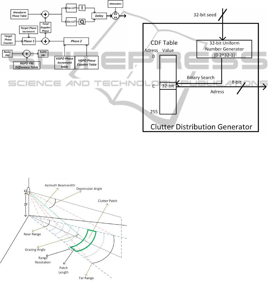
Coordinated RVGPO/I signal generator is shown
in Figure 6. For coordinated implementation parame-
ters should be set as V
0
= V
R
, V
V
= a
R
, and a
V
= J
R
.
The same signal generator can be used to generate tar-
get signals as well.
Figure 6: RVGPO/I Signal Generator.
3.3 Clutter Modeling
RTSim implements statistical clutter models.
Rayleigh, Weibull and K-distributions are supported.
In Figure 7 a typical clutter scenario is described.
For each clutter patch a random number is generated
corresponding to its range bin. The attenuation for
clutter signal is determined by the patch area, grazing
angle and distance from radar. The parameters of the
random distributions depend on the grazing angle,
polarization, radar frequency, surface’s dielectric
constant and conductivity.
Figure 7: Clutter Scenario.
Random clutter samples are generated using
inverse CDF (Cumulative Distribution Function)
method. In this method CDF of the distribution is
generated as a table, then a uniform number is gener-
ated in the interval [0 1], the index of the CDF table
that this number falls into is selected as the desired
random number. The FPGA implementation of clut-
ter distribution generator is shown in Figure 8. CDF
table contains 255 elements of 32-bit numbers which
are obtained by quantizing the CDF function of the
distribution. Uniform numbers are also 32-bits and
the generated random numbers are 8-bits.
Figure 8: Clutter Distribution Generator.
4 EXPERIMENTAL RESULTS
In the experiments the IQ signals generated by the
FPGAs are compared to the theoretical calculations.
In the first example there are four targets at distances
1343, 1460, 1656, and 1814 meters and moving with
speeds 29.83, -309.10, -347.19, -833.52 m/s. The
radar parameters are, PRI = 560 samples, PW = 100
samples, number of pulses in each burst is 64. In Fig-
ure 9 the I and Q signals generated by the simula-
tor are displayed. These signals are analyzed using
range doppler matrices. The ranges and velocities of
detected targets are shown in Figure 10. The results
agree with the input parameters.
In Figure 11 sample RGPO and target signals are
given. For this example range gate pull of is applied
with V
R
= 500 m/s. Radar signal parameters are; PRI
= 100 µs, pulse width = 20 µs, chip width = 200 ns,
number of pulses = 500 and sampling rate = 10 MHz.
As seen in the figure in approximately 1.5 seconds 50
samples pull off is applied, and this corresponds to
750 meters range difference at 5 µs.
SIMULTECH2014-4thInternationalConferenceonSimulationandModelingMethodologies,Technologiesand
Applications
670
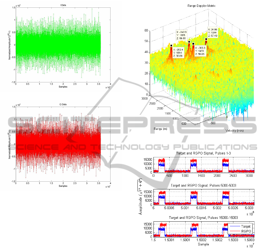
(a) I
(b) Q
Figure 9: I and Q samples for four targets.
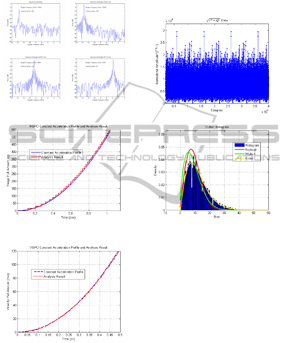
In Figure 12 spectrum estimations for target and
VGPO signals are displayed. For this example a ve-
locity gate pull off profile with V
V
= 150 m/s
2
is ap-
plied. Radar signal parameters are; PRI= 30 µs, radar
frequency = 10 GHz, number of pulses = 128, and
sampling rate = 200 MHz. Using these parameters
the maximum unambiguous velocity is 250 m/s, and
velocity resolution is 7.8 m/s. As seen from the fig-
ure in 0.5 seconds the pull off rate is 71 m/s, and in
1 second it is 143 m/s, which are consistent with the
VGPO profile.
In Figure 13 the RGPO signal generated by RT-
Sim is analyzed and the results are compared with the
real constant acceleration profile. RGPO constant ac-
celeration parameter is set to a
R
= 1000 m/s
2
. The
generated signal has 10000 bursts each of which has
a pulse of 100 µs. The sampling rate of the signal is 10
MHz. As can be seen from the figure, the generated
signal’s profile is consistent with the actual profile ex-
cept for some quantization errors.
In Figure 14 the VGPO signal generated by RT-
Sim is analyzed and the results are compared with the
Figure 10: Processed pulses for four targets.
Figure 11: Sample RGPO application. Scenario initializa-
tion, after 0.5 ve 1.5 seconds.
real constant acceleration profile. VGPO constant ac-
celeration parameter is set to a
V
= 1000 m/s
3
. The
generated signal has 130 bursts each of which has 128
pulses of 30 µs. As can be seen from the figure, the
generated signal’s profile is consistent with the actual
profile except for some quantization errors.
The final experiment is clutter generation. K-
distributed clutter with parameters shape = 4 and scale
= 2.06 is generated. Radar signal has four pulses each
with 10k samples at 40 MHz sampling frequency.
In Figure 15(a) amplitude of the generated clutter
samples is displayed. The histogram of the sam-
ples is analyzed and compared with the histograms
Hardware-In-the-LoopRadarTestSimulator
671
(a) Target Return (b) VGPO Return t = 0.0 sec
(c) VGPO Return t = 0.5 sec (d) VGPO Return t = 1.0 sec
Figure 12: Sample VGPO Application.
Figure 13: RGPO constant acceleration profile and analysis
result.
Figure 14: VGPO constant acceleration profile and analysis
result.
of Rayleigh, Weibull and K-distributions and then the
closest histogram is selected as the true histogram.
The estimated parameters are shape = 4 and scale =
2.11 which are in close agreement with the true pa-
rameters. Histogram plots are shown in Figure 15(b).
(a) Amplitude samples
(b) Histogram
Figure 15: Amplitude and histogram samples for clutter.
5 CONCLUSION
In this work, a real-time hardware-in-the-loop radar
target and environment simulator, RTSim, is de-
scribed. The simulator can be used to test radar signal
processing units even during the early stages of de-
velopment. RTSim models moving and stationary tar-
gets, radars with multiple receiverchannels, jammers,
statistical clutter returns. RTSim is currently being
used in some radar development projects in Turkish
Defence Industry. Future work includes implementa-
tion of terrain-dependentmore realistic clutter models
and atmospheric propagation models.
REFERENCES
Andraka, R. and Phelps, R. (1998). An FPGA based pro-
cessor yields a real time high fidelity radar environ-
SIMULTECH2014-4thInternationalConferenceonSimulationandModelingMethodologies,Technologiesand
Applications
672
ment simulator. In Military and Aerospace Appli-
cations of Programmable Devices and Technologies
Conference, pages 220–224.
Bell, M. and Grubbs, R. (1993). Jem modeling and
measurement for radar target identification. IEEE
Transactions on Aerospace and Electronic Systems,
29(1):73–87.
Carriere, R. and Moses, R. (1988). Autoregressive moving
average modeling of radar target signatures. In IEEE
National Radar Conference, pages 225–229.
EW Simulation Technology (2013). Radar
Target & Environment Generator.
http://ewst.com.au/index.php?option=com
content&view=article&id=14&Itemid=28.
Greco, M., Gini, F., Farina, A., and Ravenni, V. (2006). Ef-
fect of phase and range gate pull-off delay quantisa-
tion on jammer signal. Radar, Sonar and Navigation,
IEEE Proceedings -, 153(5):454 –459.
Intersoft Electronics (2013). Radar Environ-
ment Simulator. http://www.intersoft-
electronics.com/HTML/RES.html.
Jing, Y., Mei-guo, G., and Yun-jie, L. (2011). Digital real-
ization of pull-off jamming in R-V dimensions. In 4th
International Congress on Image and Signal Process-
ing (CISP), volume 4, pages 2177 –2181.
Kalata, P. and Chmielewski, T. (1997). Range gate pull
off (RGPO): detection, observability and α- β target
tracking. In Proceedings of the Twenty-Ninth South-
eastern Symposium on System Theory, pages 505 –
508.
Neng-Jing, L. and Yi-Ting, Z. (1995). A survey of radar
ecm and eccm. Aerospace and Electronic Systems,
IEEE Transactions on, 31(3):1110 –1120.
Phu, P., Adler, E., Innocenti, R., and Paolella, A. (1995).
A test target generator for wideband pulsed doppler
radars. In IEEE MTT-S International Microwave Sym-
posium Digest, pages 973–975 vol.2.
Richards, M. (2005). Fundamentals of Radar Signal Pro-
cessing. McGraw-Hill.
Saab Sensis (2013). Radar Environmental Simulator
(RES). http://www.saabsensis.com/products/radar-
environmental-simulator-res/.
Sandhu, G. and Saylor, A. V. (1985). A real-time statistical
radar target model. IEEE Transactions on Aerospace
and Electronic Systems, AES-21(4):490–507.
Schleher, D. (1999). Electronic Warfare in the Information
Age. Artech House Radar Library. Artech House.
Skolnik, M. (2008). Radar Handbook, Third Edition. Elec-
tronics electrical engineering. McGraw-Hill Educa-
tion.
Technology Service Corporation (2013). Radar En-
vironment Simulators. http://www.tsc.com/Fact
sheets/Radar Simulators Fact Sheet.pdf.
Townsend, J. (2008). Improvement of ECM Techniques
Through Implementation of a Genetic Algorithm.
Master’s thesis, Air Force Institute of Technology.
Utteridge, E. J. (1987). Radar environment simulator. In
Radar - 87; Proceedings of the International Confer-
ence, pages 520–524.
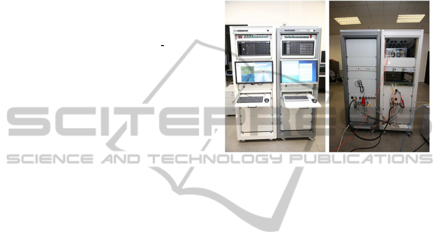
APPENDIX
Hardware components of RTSim (white rack) and in-
terface simulator for RSPUs (gray rack) is shown in
Figure 16. RSPU interface simulator is developed to
test RTSim before integration with actual radar sys-
tems.
Figure 16: RTSim and RSPU-IS hardware components.
Hardware-In-the-LoopRadarTestSimulator
673
