
Complementarity between Simulation and Formal Verification
∗
Transformation of PROMELA Models into FDDEVS Models: Application to a
Case Study
Aznam Yacoub, Maamar Hamri and Claudia Frydman
Aix Marseille Universit
´
e, CNRS, ENSAM, Universit
´
e de Toulon, LSIS UMR 7296, 13397, Marseille, France
Keywords:
Formal Methods, Spin, PROMELA, Formal Verification, DEVS, FDDEVS, Simulation, Transformation.
Abstract:
Discrete Event system Specification (DEVS) is a simple comprehensive way to describe complex discrete-
event systems in a hierarchical way. Few years ago, Finite and Deterministic DEVS (FDDEVS) was intro-
duced to support verification analysis of a subclass of DEVS problems, in the same way as formal methods.
This paper presents guidelines to transform behavioral models used in formal methods like critical sections,
especially described in PROMELA in this case, into FDDEVS models, and shows the benefits of such a trans-
formation.
1 INTRODUCTION
With the growing complexity of systems, designing
stable and robust systems has become harder and
harder. Nowadays, creating reliable software, hard-
ware or systems without any bug needs a lot of strong
knowledge and experience. But for many years,
two disciplines which make these tasks easier have
emerged: on the one hand, Modeling and Simula-
tion (M&S) allow working on a model and to perform
some tests, which are generally too expensive or im-
practical to do on the real system. In order to design
the simulated system, M&S bases the theory on as-
sumptions done from the real system; the quality of
the simulation consequently depends on the quality
of the theory about the system which is being stud-
ied (Zeigler, 1984). On the other hand, Verification
and Validation (V&V) which use formal methods al-
low guaranteeing the absence of problems on a sys-
tem by mathematical verification: using a rigourous
description of the system with a formal and expres-
sive mathematical language (like propositional logic),
these techniques ensure that the system fits on spec-
ifications by testing them as qualitative properties on
the model of the real sytem. But, modeling an entire
system with these techniques is very hard, because of
the complexity of the formalisms.
∗
This work is part of the R&D project ”MAGE”, from
French ”Investing for the Future” national program.
2 MOTIVATIONS
The work described in this paper is a part of our desire
to make M&S and formal V&V closer. Approaches
developped in both disciplines could be complemen-
tary. Finding a general method to transform formal
models into simulation models and vice versa will
then allow us taking advantages of formal verification
and simulation. In this sense, we could using simu-
lation to verify systems for which formal verification
failed.
On the one hand, Discrete Event Simulation
(DES) provides a simpler way to verify, analyze and
validate systems through a modular and hierarchi-
cal formalism: Discrete Event System Specification
(DEVS) introduced by Zeigler (Zeigler, 1976). DEVS
allows representing a full range of systems which
can be assimilated to discrete-event systems. Some
of the advantages of DEVS Framework, as a funda-
mental requirement of the M&S theory, is the separa-
tion of modeling from simulation, enabling reusabil-
ity, stand-alone testing and hierarchical construction.
Furthermore, the expressiveness of the DEVS formal-
ism makes modeling easier, and identification of a
specific experimental frame appropriate to a model
makes easier the uncovering of assumptions on the
real system. But, that also means that simulation
is depending on specific scenarii, and allows testing
the system only in some circumstances, unlike formal
methods which guarantee the correctness of the sys-
tem in all cases.
421
Yacoub A., Hamri M. and Frydman C..
Complementarity between Simulation and Formal Verification - Transformation of PROMELA Models into FDDEVS Models: Application to a Case Study.
DOI: 10.5220/0005037904210426
In Proceedings of the 4th International Conference on Simulation and Modeling Methodologies, Technologies and Applications (SIMULTECH-2014),
pages 421-426
ISBN: 978-989-758-038-3
Copyright
c
2014 SCITEPRESS (Science and Technology Publications, Lda.)

On the other hand, V&V can encounter in few
cases, especially with model-based formal methods,
some difficulties like the State Explosion Problem for
instance. When the system grows up, the size of the
state space exponentially also grows. Even model
cheking tools like SPIN are able to verify models
with 10
120
states thanks to the use of Binary Decision
Diagrams (BDD) for the representation of the state
space (Miller et al., 2010), these verification tools do
not fit to bigger systems. Formal verification can not
apparently likewise verify systems with an uncount-
ably infinite state space in practice. For these cases,
simulation approach could be a very interesting com-
plementary approach to the verification tools, espe-
cially as FDDEVS supports both verification and sim-
ulation.
Due to the fact that there are many various tech-
niques used in each of these disciplines, we only fo-
cus here on two formalisms, in order to validate our
approach: FDDEVS (Hwang and Zeigler, 2006a) and
PROMELA (Holzmann, 2004). One must keep in
mind that the approach which we want to develop
does not depend on the choice of the formalisms. Fi-
nite and Deterministic Discrete Event-system Speci-
fication (FDDEVS) is a subclass of DEVS problem,
which is used to describe, model and simulate dis-
crete event systems. Discrete Event Systems (Zeigler,
1976) are those whose the evaluation of their current
state is done at some specific points in the time, called
events. Across that, PROMELA is especially used to
describe, model and verify asynchronous and concur-
rent systems. In these terms, reader can think that
the case studies concerned with one or the other of
these languages, and the goals of these two domains
are totally disconnected. Moreover, it is legitimate
to ask how simulation could bring something to ver-
ification: indeed, the simulation is by nature an em-
pirical method while the verification is an exhaustive
method.
We will then introduce here a way to transform
PROMELA models into FDDEVS models through
one example, and show why using a simulation ap-
proach could be beneficial for formal methods in
some cases, before speaking about the possible con-
tributions of such a method for both domains.
3 VERIFICATION OF THE
DEKKER’S ALGORITHM
In this paper, we will exclusively handle our problem
through one example which is representative of clas-
sic problems concerned by V&V and model-based
formal methods. Our work introduced in this paper
is thus based on the problem of mutual exclusion, and
especially its resolution by the Dekker’s algorithm.
3.1 The Dekker’s Algorithm of the
Mutual Exclusion Problem
The Dekker’s algorithm of mutual exclusion was in-
troduced in 1965 by Theodorus Dekker, according to
Dijkstra (Dijkstra, 2002). This is the first and a rel-
atively simple solution for a well-known problem in
concurrent systems: the mutual exclusion that allows
two processes accessing a shared critical resource.
The algorithm for a process p considers two vari-
ables b
p
, b
q
, and a flag k. The two first boolean vari-
ables indicate whether processes p and q want to ac-
cess to the critical resource or not. If both of them
wish to reach the resource, the flag k acts as a referee
and indicates which of them can immediately have
the resource. Then, the process, which is forbidden
to enter the critical section, turns his willingness flag
to false and enters active waiting while the other pro-
cess enters the critical section. At the end, the pro-
cess, which had the resource in this turn, sets the flag
k to the value of the other process, that guarantees the
fairness property which ensures processes are fairly
executed.
3.2 Verification by Model-checking
Model-checking is a model-based formal
method (Huth and Ryan, 2000) in which the
considered system is described as a state transition
system M used by the model-checker to verify if
M φ, where φ is a set of properties expressed
in a temporal logic. Among all model-checking
languages, our work is focusing on PROMELA
language introduced by Holzmann (Holzmann,
1997) (Holzmann, 2004). PROMELA was especially
designed to verify dynamic concurrent systems,
which are then translated into non-deterministic
automata. Properties which must be verified are
expressed in Linear Temporal Logic (LTL) before
being translated into B
¨
uchi Automata. The SPIN
model-checker performs verification on these two
final models. Moreover, the SPIN model-checker can
also operate as a simulator, which allows us making a
good comparison between this tool and our approach
with the FDDEVS simulator.
The PROMELA implementation of the Dekker’s
algorithm (given in Program 1) is very natural, thanks
to the characteristics of the language. Processes are
expressed as proctype blocks, and communication
between both of them is done through global variables
wantp, wantq and turn, which respectively represent
SIMULTECH2014-4thInternationalConferenceonSimulationandModelingMethodologies,Technologiesand
Applications
422

Figure 1: Automata generated by the PROMELA imple-
mentation of the Dekker’s algorithm.
the variables b
i
, b
j
and k. The boolean variables csp
and csq mean that the processes p and q are respec-
tively in the critical section or not. In this example,
we also test the safety property (line 5) : ”The pro-
cesses p and q never enter the critical section at the
same time”.
The SPIN model-checker thus verifies the LTL
property by firstly translating the property into a
B
¨
uchi automaton, and then by computing the syn-
chronous product between this automaton and the
asynchronous product of two others automata that
represents the processes p and q (Figure 1). The
emptiness of the language accepted by the resulting
automaton indicates whether the property is satisfied
or not (Holzmann, 1997).
The total state space of the final reachability graph
thus includes 148 states, and 279 transitions. In 131
cases, transitions led to a path already verified. It will
be interesting to remember it, when we will compare
this verification method with new one that we will in-
troduce later.
Note that the verification by the model-checking
method has many advantages. Among them, trans-
lation from the informal algorithm is very intuitive.
Moreover, SPIN is a mature tool with many efficient
algorithms to reduce the total state space and increase
the speed of the verification. The use of LTL is also
a good thing, because the verification is then based
on a simple logic formula. Furthermore, SPIN inte-
grates a simulation tool which allows engineers ver-
ifying the trace of the execution of the program. In
this case, verification by model-checking seems to be
an easy and safety way which ensures that a system
has no bug relative to the given specifications. How-
ever, M&S provides another approach for problem
modelling. DEVS and its subclass FDDEVS were
designed (Hwang and Zeigler, 2006a) to formalize
discrete-event systems in a very intuitive way. We
show in the next section how to simulate and verify
the Dekker’s Algorithm with the FDDEVS formal-
ism.
Program 1: Implementation of the Dekker’s algorithm in
PROMELA
1: bool want p = f alse, wantq = f alse;
2: byte turn = 1;
3: bool csp = f alse, csq = f alse;
4:
5: ltl { []!(csp and csq) }
6:
7: active proctype p() {
8: do
9: :: want p = true;
10: do
11: :: !wantq → break;
12: :: else →
13: if
14: :: (turn == 1)
15: :: (turn == 2) →
16: want p = f alse;
17: (turn == 1);
18: want p = true;
19: fi;
20: od;
21: csp = true;
22: csp = f alse;
23: want p = f alse;
24: turn = 2
25: od;
26: }
27: [... the process q is symmetrical to the process p
...]
4 THE DEKKER’S ALGORITHM
AS A FDDEVS
4.1 Simulation-based Verification
As we previously said, discrete-event simulation pro-
vides a more natural way for modelling, verification
and validation of discrete-event systems. Simulation
is done under specific conditions, called Experimental
Frame (EF) (Zeigler, 1976). Simulation-based verifi-
cation consists then to verify that outputs produced by
the model for a specific EF (in others terms, for spe-
cific inputs) meet some system requirements or spec-
ifications. Simulation also allows verifying the be-
haviour of a system, meaning its real evolution, unlike
ComplementaritybetweenSimulationandFormalVerification-TransformationofPROMELAModelsintoFDDEVS
Models:ApplicationtoaCaseStudy
423

formal methods which only guarantee that the model
meets requirements under all circumstances. In oth-
ers words, simulation allows understanding how the
system reacts when an unexpected event occurs. Sim-
ulation, thus, provides not only a way to verify that a
system meets requirements in an EF, but also allows
understanding how it evolves in the time. It’s why
we believe using jointly simulation and formal veri-
fication ensures that the system of interest meets ini-
tial specification in all cases and its behaviour (its real
temporal evolution) conforms to what was expected.
4.2 Introduction to FDDEVS
Finite and Deterministic Discrete Event-system Spec-
ification (FDDEVS) is a formalism based on the
DEVS formalism (Zeigler, 1976) and introduced
in (Hwang and Zeigler, 2006a) to model and analyze
discrete event systems in both simulation and verifi-
cation ways. Like DEVS, FDDEVS allows modular
and hierarchical modeling and simulation.
Formally, a FDDEVS atomic model is defined as
a DEVS atomic model with three restrictions, given
by:
• X and Y , the set of input/output events are finite;
• τ : S → Q
[0,∞]
which defines the lifespan of each
state on Q
+∞
(and not R);
• δ
x
: S × X → S ×{0, 1} which is the external tran-
sition function. If δ
x
(s, x) = (s
0
, 0), the schedule
is preserved, otherwise time is updated by τ(s
0
);
FDDEVS coupled model is defined as DEVS cou-
pled model.
4.3 PROMELA to FDDEVS
Transformation Rules
As we said, FDDEVS allows analysis of problem
in simulation way, in the same manner as DEVS. It
is thus interesting to compare the analyzing of the
Dekker’s algorithm provided in the previous section,
and the results obtained with a simulation approach
using FDDEVS.
Note that, instead of modeling the problem from
the informal Dekker’s algorithm, we directly wanted
to obtain the FDDEVS model from the PROMELA
code. Firstly, we know that the PROMELA imple-
mentation of the Dekker’s algorithm can be translated
to a FDDEVS model. If we consider how SPIN sim-
ulation is working, we can decide that the execution
of each line of the PROMELA code corresponds to
an event in our FDDEVS model. In fact, we consider
only the change of the value of each variable wantp,
wantq and turn as done by an internal or an exter-
nal event. Moreover, we saw in the section 3.2 that
the sets of state of each automata representing each
process in PROMELA are finite sets. The second and
third restriction of a FDDEVS can be arbitrary de-
cided in our case, because no explicit time restriction
appears in the PROMELA verification way.
Now we know we can translate the PROMELA
code into a FDDEVS model, we slightly change the
algorithm for convenience: instead of global variables
wantp, wantq and turn, we consider three variables
want
me
, want
other
and my turn for each process. In
the same way, we consider csp and csq variables as
local variables (and not as global variables anymore).
Besides, lines wantp = false; turn = 2 and wantq =
false; turn = 1 are considered as atomic instructions.
Then, we define each process as an atomic FDDEVS
model defined by :
P =< X,Y, S, s
0
, τ, δ
x
, δ
y
>
where
• X = {?W
o
, ?
¯
W
o
, ?T
c
}, where ?W
o
denotes the other
process wants to enter critical section, ?
¯
W
o
de-
notes the other process does not want to enter the
critical section anymore, ?T
c
denotes the change
of the value of the my turn variable;
• Y = {!W
m
, !
¯
W
m
, !T
c
}, where !W
m
is sent when the
current process wants to enter critical section, !
¯
W
m
is sent when the current process doesn’t want to
enter the critical section anymore, !T
c
is sent when
the current process leaves the critical section;
• S = {(want
me
, want
other
, my turn) ∈ {0, 1} ×
{0, 1} × {0, 1}} ∪ {Cr} ∪ {Wait}, where want
me
means if the current process wants to enter critical
section, want
other
the other process wants to enter
critical section, my turn if the current process
has the priority upon the critical section; the
state ”Cr” means the current process is in critical
section; the state ”Wait” represents the active
waiting of the lines 14-18 of the PROMELA
code;
• s
0
= (0, 0, 0) or s
0
= (0, 0, 1) depending on the
value of the turn variable in the PROMELA code;
Now, in order to make the transition table of each
FDDEVS atomic model and to define the transitions
functions, we apply the following rules :
1. Each modification of a global variable leads to a
new state;
2. The initial state of each FDDEVS atomic model
depends on the turn variable. If turn is equal to
1, the process P
1
is in s
0
= (0, 0, 1) and P
2
in s
0
=
(0, 0, 0), otherwise P
1
is in s
0
= (0, 0, 0) and P
2
in
s
0
= (0, 0, 1);
SIMULTECH2014-4thInternationalConferenceonSimulationandModelingMethodologies,Technologiesand
Applications
424

3. When the value of a global variable is changed,
the process which changes the value emits an
output event before exiting its current state by
the internal transition function; the other process
changes its current state when it receives the input
event;
4. If a state is changed by an input event, the internal
schedule is preserved;
5. Lifespan of each state s is given by τ(s) = 0 except
for the states (1, 1, 1) and Wait (because the loop
condition only depends on the value of a global
variable which is not udpated in the loop).
With these rules, we obtain the following FD-
DEVS model in Figure 2.
5 RESULTS AND DISCUSSION
5.1 Verification with FDDEVS
Framework
After designing the FDDEVS model, we implement
it using the Hwang’s Framework (Hwang and Zeigler,
2006a) which generates a reachability graph (Hwang
and Zeigler, 2006b) of 13 vertices and 17 edges for
the verification. The property G¬(csp ∧csq) was ver-
ified by checking if a state exists in the reachability
graph for which both processes are in the Critical
state. Moreover, the simulation with DEVS shows the
importance of the execution order of the instructions.
Indeed, the lifespan of each state directly influences
on the scenario of the model. We see, with the con-
figuration where τ(s) = 0 for each state, that process
p directly enters critical section, and the active wait
problem is never encountered. But, if τ(s) = α with
α > 0, then the scenario given by the model is the sce-
nario where both processes want to enter critical sec-
tion at the same time. Scenario of simulation is then
included in the model given by the transformation. In
fact, this problem comes from the precedence of ex-
ternal transition upon internal transition, or the inter-
nal transition upon external transition. In other words,
if two events occur at the same time, the model will
give the priority to the internal transition or external
transition according to a δ
con f luent
function defined by
δ
con f luent
: S × X → S, that leads to repeat only one
possible execution. This problem could be solved by
generating one model per state of the base FDDEVS
atomic model, in which we change the δ
con f luent
func-
tion to change the priority of the events. But, for the
Dekker’s Algorithm, the critical point is when both
processes want to enter the critical section at the same
time, so only two coupled models are needed to cover
the verification of the entire problem.
Moreover, the transformation shows something
which is implicit in the PROMELA model: if the ex-
ecution order of the instructions is not really taken
into account in the algorithm, it depends on the sys-
tem, meaning the FDDEVS model better represents
the reality of the operating system scheduler than the
PROMELA model, although model-checking verifies
all possibilities of execution too.
Furthermore, because of the size of the reachabil-
ity graph obtained by this method, we show trans-
formation could be really economic to verify some
targeted scenarii. Then, instead of directly verifying
the PROMELA model for all scenarii, designers and
modelers could use transformation to verify precise
scenarii, before using the model-checker tools.
5.2 Discussion around ”Wait” State and
”Critical” State
There is another problem of the method introduced
in this paper. It concerns the wait active loop given
in the lines 14-18, which we redesigned as a Wait
state for convenience and simplification. In the
same way, considering lines following the exit as
atomic instructions was a great simplification. In
fact, if we rigourously apply our method, the atomic
model of process would be incorrect for some rea-
son. Firstly, applying rigourously our method would
force to create internal transition to the existing state
(0, 1, 0). But because τ(0, 1, 0) = 0 by definition, pro-
cess would try again to go to (1, 1, 0) at the end of the
lifespan, which is not the behaviour of the algorithm.
Besides, because we cannot redefine the τ function,
we must then define our state space as a set of 4-uplet
S = {(want
me
, want
other
, my turn, α)} ∪ S
0
where
S
0
= {Cr} ∪ {Wait}
want
me
, want
other
, my turn ∈ {0, 1}
α ∈ A
and A is a finite set of real values, and redefine our τ
function like
∀s ∈ S, τ(s) = α
in order to solve this problem. This leads to differ-
entiate states by their lifespan, but it is not a satisfy-
ing solution because it corresponds to a transforma-
tion based on semantics. We could also argue that the
need to define a lifespan value for each state is also
based on semantics. However, the method we previ-
ously introduced allows defining default values. For
instance, if loop condition only depends on a global
ComplementaritybetweenSimulationandFormalVerification-TransformationofPROMELAModelsintoFDDEVS
Models:ApplicationtoaCaseStudy
425
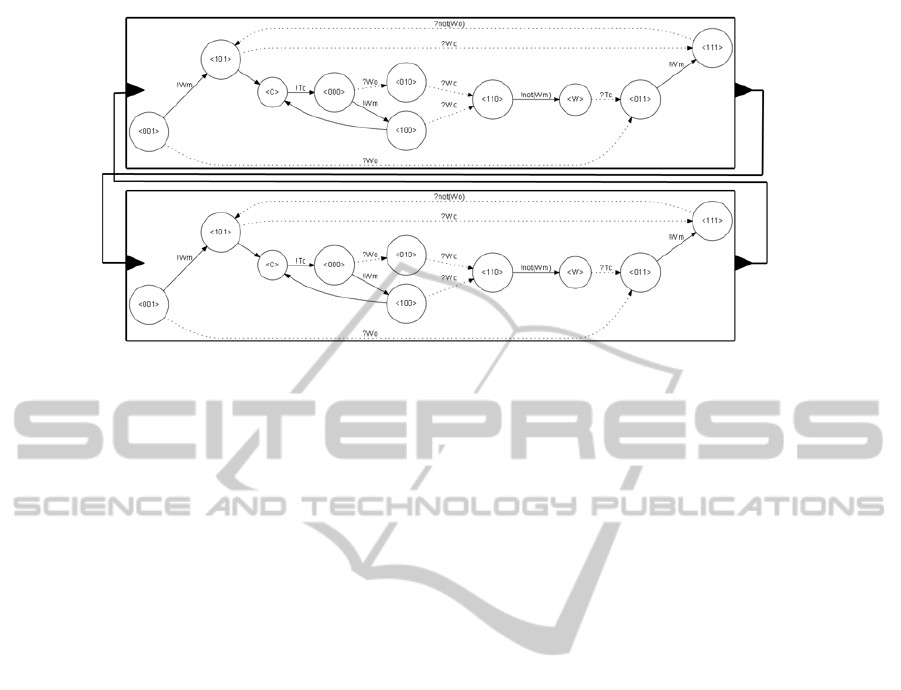
Figure 2: FDDEVS Coupled Model of the Dekker’s algorithm.
variable, then we could decide that the lifespan of the
corresponding state will be ∞. Otherwise, the lifespan
will be equal to 0, as we previously defined.
In the same way, the state Critical creates the
same problem if we don’t consider the instructions
following the exit as atomic instructions.
6 CONCLUSION AND FUTURE
WORKS
In this paper, we showed we can translate a for-
mal algorithm written in PROMELA into a FDDEVS
model, which supports verification and simulation.
The transformation has the advantage to allow veri-
fication of some interesting scenarii in a reduced state
space, in comparison with the state space generated
by the model-checker. Moreover, the resulting model
is more representative model the reality, in the sense
that time is thus explicitely expressed. Taking into ac-
count that, transforming the PROMELA model into
a FDDEVS model allows working on a complemen-
tary model during the design phase. A simulation
with SPIN executes instructions step-by-step allow-
ing simulation of randomness of the processor, but
working on an explicit temporal model has the ad-
vantage to allow explicit changes of the behaviour
of the system over time. However, semantic changes
done on the initial PROMELA code, in order to pro-
duce a good equivalent FDDEVS model, raises the
legitimate question about the equivalence of the mod-
els. These changes based on semantic was intended to
make feasible the transformation, but we must show
they allow expressing the same system. Moreover, the
method introduced in this paper also opens the ques-
tion of the generalizability of this approach to any oth-
ers formalisms and any others systems, and also of the
automaticity of the transformation.
REFERENCES
Dijkstra, E. W. (2002). The origin of concurrent pro-
gramming. chapter Cooperating Sequential Processes,
pages 65–138. Springer-Verlag New York, Inc., New
York, NY, USA.
Holzmann, G. J. (1997). The model checker spin. IEEE
Trans. Softw. Eng., 23(5):279–295.
Holzmann, G. J. (2004). The SPIN Model Checker - primer
and reference manual. Addison-Wesley.
Huth, M. and Ryan, M. (2000). Logic in Computer Science:
Modelling and Reasoning about Systems. Cambridge
University Press.
Hwang, M. H. and Zeigler, B. P. (2006a). A modular
verification framework using finite and-deterministic
devs. In Proceedings of 2006 Spring Simulation
Multi-Conference: Proceedings of 2006 DEVS Sym-
posium, pages 57–58. Huntsville, AL.
Hwang, M. H. and Zeigler, B. P. (2006b). A reachable
graph of finite and deterministic devs networks. In
Proceedings of 2006 Spring Simulation Multi- Confer-
ence: Proceedings of 2006 DEVS Symposium, pages
48–56, Huntsville, AL, USA.
Miller, S. P., Whalen, M. W., and Cofer, D. D. (2010).
Software model checking takes off. Commun. ACM,
53(2):58–64.
Zeigler, B. P. (1976). Theory of Modeling and Simulation.
John Wiley.
Zeigler, B. P. (1984). Multifacetted Modelling and Discrete
Event Simulation. Academic Press Professional, Inc.,
San Diego, CA, USA.
SIMULTECH2014-4thInternationalConferenceonSimulationandModelingMethodologies,Technologiesand
Applications
426
