
Development of 3D Simulation System for Multi-Axis Turn-Mill
Machining
Hong-Tzong Yau, Jhih-Long Chen, Bing-Rau Yu and Tsan-Jui Yang
Advanced Institute of Manufacturing with High-Tech Innovations, National Chung Cheng University, Chia-Yi, Taiwan
Keywords: NC Simulation, Turn-Mill Machining, Material Removal, Solid Model.
Abstract: This paper proposes a 3D simulation system for multi-axis turn-mill machining. With the diversification of
technology products, traditional three-axis machining has been unable to meet the needs of existing
industries. Multi-axis machining system with high processing efficiency and accuracy has gradually become
the mainstream, and is widely used to produce high-value-added products, such as aerospace components
and medical devices. Since multi-axis machining hardware is very expensive, how to ensure the generation
of correct NC paths and avoid machine collisions from happening become important challenges. In this
paper, the triangular mesh model is used to represent the cutter, machine parts and materials. The actual
movement of the machine can be simulated after G codes are parsed. For the material removal, taking
processing speed into consideration, this paper proposes a hybrid simulation mechanism including 2D
intersection, Z-map and Boolean operations. This proposed method can obtain better result in terms of
processing efficiency and machining precision. At the same time, collision detection is used to find
interference between tools and machines. Using experiments, this paper demonstrates a variety of turn-mill
machining examples to verify the feasibility of the proposed method.
1 INTRODUCTION
Recently, computer numerical control (CNC) multi-
axis milling machine has become a main approach
for maching complex objects. The advantages of
multi-axis milling include efficiency, accuracy and
cost-effectiveness. The multi-axis milling machine is
more suitable for milling complex free-form
surfaces than the traditional 3-axis milling machine.
Moreover, it can provide better surface quality and
less surface roughness. However, after milling, most
mechanical components still require turning,
grinding, drilling and tapping. Therefore, part
moving, mounting and tool calibration need to be
repeated in the subsequent procedures.
In order to overcome this bottleneck, a CNC
turn-mill machine provides a more complete
solution. The advantages of the CNC turn-mill
machine include shortened machining time,
increased production, and decreased cost.
With the improvement of CAD/CAM
technology, intellegent or smart machine is growing
vigorously. The intelligent monitoring and
interactive 3D machining simulation can increase
the added values of NC machines. However, a
voxel-based rendering is used in most simulation
software. This kind of rendering is inefficient
because it needs much memory space and computing
power to provide accurate visualization. In this
paper, a polygon-based representation model with Z-
map and Boolean operations is proposed to simulate
the practical machining process in the turn-mill
machine.
The aim of this paper is to propose a 3D
simulation system for multi-axis turn-mill
machining. After loading the machining parameters
and NC paths, the simulated workpiece, tooling
turret and cutter can be generated automatically.
With 3D collision detection, the simulation can be
carried out more intuitively in different kinds of
machining situations.
2 LITERATURE SURVEY
2.1 NC Simulation
Real-time simulation for virtual machining process
is an important key, and pre-processing and good
hardware are necessary to enhance the performance
717
Yau H., Chen J., Yu B. and Yang T..
Development of 3D Simulation System for Multi-Axis Turn-Mill Machining.
DOI: 10.5220/0005039907170724
In Proceedings of the 4th International Conference on Simulation and Modeling Methodologies, Technologies and Applications (SIMULTECH-2014),
pages 717-724
ISBN: 978-989-758-038-3
Copyright
c
2014 SCITEPRESS (Science and Technology Publications, Lda.)

efficiency (Kerning, 2010). Generally, NC
simulation can mainly be categorized into three
approaches. The first approach uses direct Boolean
intersection of solid models to calculate the volume
of material removal during machining (Huang,
1995). This approach is theoretically capable of
providing accurate NC simulation, but this method
has the drawback of expensive computation. The
second approach uses spatial partitioning
representation to represent a cutter and work-piece
(Kim, 2006). In this approach, a solid object is
decomposed into a collection of basic geometric
elements, which includes Z-map, voxel and ray
representation. Voxel and Octree (Jang, 2000) is
another popular 3D decomposition approach which
is used to develop NC simulation system. However,
the disadvantages of Voxel and Octree are mainly
the high memory requirement and poor boundary
accuracy. The third approach uses discrete vector
intersection (Chang, 1991). Discrete vector method
is one of the most efficient methods in NC
simulation. Z-map simulation can be classified as a
special case of discrete vector method. However,
this method does not directly generate a solid model
for the machined part and is not suitable for cases
with dramatic normal changes during simulation.
2.2 Z-map Simulation
For Z-map machining simulation, the larger grid size
will lead to faster simulation speed but poor
accuracy. On the contrary, smaller grid size can
improve the simulation result but resulting in low
efficiency. (Lee, 2002) proposed enhanced Z-map
method which can satisfy the requirements of
efficiency and accuracy. Some algorithms (Maeng,
2003~2004) calculate the intersection of cutter swept
volume and work-piece, and adjust its z value to
achieve the simulation results. (Cai, 2010) presented
a general simulation methodology based on a Z-map
model of work-piece for predicting surface
topographic features and roughness formed in the
finish milling process. (Tsai, 2013) calculated mesh
position and z coordinates of tool scanning surface
according to tool path and initial tool scanning
boundary in reducing the long computation time.
This method can simulate not only straight line and
arc but also nonlinear path, like helical and spline
curves.
2.3 Boolean Operation
The difference set of Boolean calculation is widely
used in CAD/CAM and reverse engineering and is
considered to be able to achieve the purpose of
accurate material removal. About the type of
computation, (Tayebi, 2011) assort them into four
different categories: exact arithmetic methods,
approximate arithmetic methods, interval
computation methods and volumetric methods. (Mei,
2013) described a simple and robust algorithm for
triangular mesh Boolean operators; their method can
deal with both manifold and non-manifold cases.
(Wang, 2011) presented a new approach to compute
the approximate Boolean operations of two freeform
polygonal mesh solids efficiently with the help of
Layered Depth Images. (Reqiuicha, 1985) explored
the boundary condition and merge of solid model,
including dealing with coplanar issues.
2.4 Collision Detection
The main concept of collision detection is to test the
intersection of bounding volumes of objects. If there
is no collision between bounding volumes of objects,
it means that there is no collision for measured
models and does not need further interference tests.
(Chan, 2003) proposed an algorithm which can
specifically define the axis-aligned bounding box of
an object. (Hutter, 2007) added triangular mesh
information into bounding volume hierarchy to
increase the effectiveness of collision detection.
(Curtis, 2008) extended the above mentioned
method and simplify the detection rules to accelerate
calculation efficiency.
3 RESEARCH METHOD
This paper presents a 3D simulation system for
multi-axis turn-mill machining. In the machining
simulation system, the main consideration is the
simulation efficiency. In order to obtain the balance
between efficiency and accuracy, this paper uses the
mainstream triangular mesh model as our basis
format to represent the work-piece. And in our
machining simulation algorithm of material removal,
we propose a hybrid mechanism to choose among
the algorithms of Deformation of Intersection Point
(DIP), Z-map and Boolean. The system will
automatically determine the appropriate algorithm
according to the different machining processes. For
example, DIP is for turning process, Z-map is for
milling process and Boolean takes all situations that
Z-map can't handle, like drill or chamfer. The blue
arrow in Figure 1 shows it can support the
deformation of DIP and Z-map. Besides, the DIP
and Z-map are also of mutual assistance. That's why
SIMULTECH2014-4thInternationalConferenceonSimulationandModelingMethodologies,Technologiesand
Applications
718
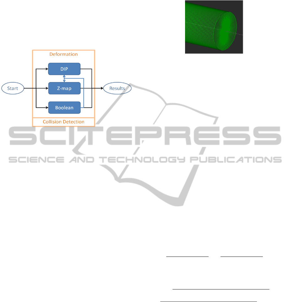
our system can handle the mixed case of turning and
milling process. Additionally, to increase the
simulation value and ensure the machining accuracy
of the tool-path, the system will detect the collisions
between tools and the machine in the whole
simulation process.
Figure 1: Flow chart of our simulation process.
4 ENVIRONMENT
CONSTRUCTION
4.1 Parameter Setting
First, the program will load the related files and
parameters before the machining simulation starts.
The detailed descriptions of each of these files are as
follows:
1. Initial parameters of program: material types,
jaw types and G30 coordinates of origin.
2. NC file: data of NC path.
3. Material file: User-defined 2D point group of
raw material block.
4. Jaw file: User-defined 2D point group of jaw.
5. File of process and parameter: name of
processes, parameter of tools and of tool colours.
4.2 Work-piece Construction
Based on the 2D plane concept of a turning machine,
the system will draw the material profile on a 2D
plane. Then we use the polar coordinates to rotate
material profile 360 degrees on the Z axis and build
the triangular mesh model. Users can adjust the
mesh density to their needs. The material shape is
drawn by users. However, the system will
automatically determine the mesh size of the
material model by considering the follow-up
deformation and the situation of the NC code. The
following figure shows a cylindrical material was
made by this method.
Figure 2: Work piece shown in triangular grid.
5 SIMULATION OF MATERIAL
REMOVAL
5.1 Deformation of Intersection Point
(DIP)
In turning simulation process, we can get several
intersections by each step using vertical line,
horizontal line or every connected line of two NC
points. As long as with correct orders of the NC path
track, we can get the 2D shape’s point group after
deformation. Furthermore by revolving the original
point group 360 degrees, we can create the 3D space
points after the material removal. The line-line
intersection equation of this paper is as follows:
There are two line equations L1 and L2 in the 2D
space. Two points on the line of segment L1 are
(x1,y1), (x2,y2). The other points on the line of
segment L2 are (x3,y3), (x4,y4). The intersection
points of two segment lines are as follows:
1
1
1
1
1
1
1
1
1
1
1
1
1
1
1
1
1
1
1
1
1
1
1
1
(1)
,
,
(2)
If the two lines are parallel, then
0
(3)
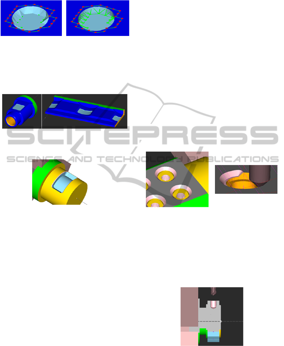
In Figure 3, the points in order 1,2,3,4 are points of
the tool shape. The program will determine the point
is taken or not, based on if it is inside or outside. If it
is inside then it is taken, if not find the intersection
point with the other points of the tool shape.
Developmentof3DSimulationSystemforMulti-AxisTurn-MillMachining
719

Figure 3: Illustration of deformation algorithm.
Figure 4 is the result of turning simulation.
In Figure 4(a), it is a simplified schematic drawing
showing the intersection points and the deformation
result of turning. In Figure 4(b), we show the result
of simulation with a tilted angle.
(a) (b)
Figure 4: The result of turning simulation.
5.2 Z-map
Z-map is the second method of material removal in
simulation in this paper. The Z-map method has one
advantage: it does not break up the mesh model. It
has been widely used in 3-axis milling simulation.
The main principle is changing the depth of point
group of the mesh to get simulation results of
material removal by the path of the sweeping tool. In
implementation, our research uses Tree data
structure to accelerate the search efficiency. Along
the cutter movement, the G01 NC segment will be
divided into three areas: Circle A (red), Circle B
(yellow), and Rectangular C (blue). In real situation,
path is continuous. When the mesh grids are marked
under these three areas and ready for deformation,
the system only deals with the parts of Circle B and
Rectangular C. Figure 5 is a mesh model and we use
it’s triangular grid endpoints to establish the Z-map.
Figure 6 shows the tool is moved linearly during the
simulation. Figure 7 shows the tool is moved in an
arc during the simulation. Marked sections of grid
are Circle A(red), Circle B(yellow) and fan-shaped
C(pink), and we only need to deal with B and C.
In general, if we only use the Z-map to push grid
points, it is difficult to keep the accuracy in
simulation. Just like Figure 8, the only thing one can
Figure 5: Mesh model for Z-map.
Figure 6: Straight path.
Figure 7: Circular path.
do is to increase the grid density to approximate the
real machining results. Hence, we propose the
concept of “grid folding” as shown in Figure 9. It is
using the idea of taking apart one grid into five grids.
In the middle there will be two segments of sharp
boundary generated intersection points. When the Z-
map pushes the grids with a flat end-mill, the
boundary grids need to be “extended” by the
additionally generated intersection points. At this
moment, using the intersection points as folding
points, we can obtain the sharp edges in the
boundary. Figure 9 shows that the required accuracy
can be reached using this method.
Figure 8: Inaccuracy
situation.
Figure 9: Grid
folding.
The actual test results are as follows, Figure 10(a) is
the result of the original grid, and Figure 10(b) is the
result after grid folding. Using such method, we can
get the good simulation result without the increase
of grid density by subdivision.
In the simulation of the mixed case of turning
and milling, the Z-map method can be further
extended by combining the use of polar coordinates
transferred to the Y axis and the C axes. The polar
coordinates can be “flattened out” as in Figure 11(b),
SIMULTECH2014-4thInternationalConferenceonSimulationandModelingMethodologies,Technologiesand
Applications
720
(a) (b)
Figure 10: The results before and after.
the simulation is performed by the Z-map, and the
result is then “folded back” as in Figure 11(a).
Figure 12 shows the simulation result using this
extended Z-map approach.
(a) (b)
Figure 11: The results of “folded back” and “flattene
d
out”.
Figure 12: Simulation results.
5.3 Boolean Operation
Boolean operation plays an important role in
geometric processing, which aims to obtain union,
subtraction and intersection of geometric models.
Theoretically, an accurate material removal model
may be obtained through the Boolean operation. But
the drawback is expensive computational loading.
For machining simulation, the required efficiency
may not be achieved. The purpose of this paper is to
achieve the material removal simulation process, and
therefore only consider the difference operator. Here,
we implement a simple and robust Boolean
algorithm proposed by (Mei, 2013); the operational
flowchart of difference operators is as follows:
Step 1: Roughly search the candidate intersection
triangle-pairs by bounding box detection and
removal of coplanar triangle-pairs with plane
projection algorithm.
Step 2: Compute the intersection line for each pair
of triangles. Merge all the segments into a loop as
expansion boundary.
Step 3: Split cutter and work-piece according to the
intersection loop.
Step 4: Decide seeds on both cutter and work-piece.
Execute region growing method to define removal
part based on mesh topology.
Step 5: Merge all the sub-surfaces which are defined
as “reserve” to form a new model.
Since the using Boolean operators must pay a higher
cost, if we simply use Boolean operators as a way to
remove the material, it will result in inefficient
simulation with a higher cost. Therefore, in general,
Z-map will be considered as the first method for
deformation. The timing of using Boolean is when
the Z-map fails to generate correct deformation. In
this system Boolean is mostly used for drilling and
chamfering editing and other related actions, for
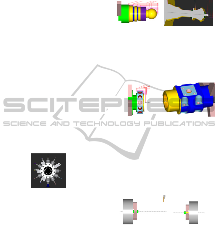
example, reaming of thread or chamfer. Figure 13
and 14 indicate drilling and chamfering examples
where Boolean operations are used.
Figure 13: Drilling.
Figure 14: Chamfering.
In addition, in drilling there could be a special case
of coplanar problem and we have a special process
to deal with it. For example, Figure 15 is the drilling
case we used. Using NC path points to exclude the
grids and the lines on the co-plane, there will be no
incorrect intersection lines during the process of
Boolean. This can help avoid mistakes and prevent
Boolean failure from happening.
Figure 15: The drilling case has co-planar situation.
Developmentof3DSimulationSystemforMulti-AxisTurn-MillMachining
721
6 SIMULATION OF TURN-MILL
PROCESS
The main purpose of this work is to construct 3D
simulation of turn-mill process. In addition to
adopting triangular mesh model to represent every
work-piece, we also create realistic tools and turrets
for the simulation of the turn-mill process. This
includes different characteristics of turning and
milling machines so it can be widely used in various
practical planning situations. In this section we will
show actual industry examples and demonstrate the
feasibility of the proposed system.
6.1 Emulated Turret Construction
In the beginning, this paper mentioned that we hope
to create an emulated turn-mill machine. Therefore,
our goal is to construct turrets and tools based on
real machine information as much as possible. The
database of tool and turrent (STL files) was provided
by a CNC factory. Figure 16 shows that if the user
opens turret viewing function, he can examine the
turret at the front view (or any views). This will help
the user easily check the tools one by one by rotating
the tools counter-clockwise.
Figure 16: The realistic turret.
6.2 Turning
The first part of this software development is turning.
This system not only includes outside turning and
inside turning, but also circular and screw cutting
paths. Unlike other general lathe simulation software
which provides only 2D turning simulation, this
system provides true 3D simulation using triangular
solid meshes. This not only provides realistic
material removing process, but also is very useful
for 3D collision detection between work-piece and
machine structures including turrets. Figure 17 and
18 show two such examples.
6.3 Milling
The second important part of this software
development is milling. At the end of each turning
Figure 17: Result 1.
Figure 18: Result 2.
process, this system will convert the object into a
triangular mesh for Z-map or Boolean simulation.
Most milling simulations are performed using the Z-
map method. Boolean operations are employed for
chamfering or other complex functions such as
drilling or internal threading. Figure 19 and 20 are
other two difficult simulation cases.
Figure 19: Results.
Figure 20: Results.
6.4 Sub-spindle
Most turn-mill machines often come with a sub-
spindle. Therefore, our system also adds a sub-
spindle module, making this simulation more
versatile. Figure 21 shows machining the work-piece
under the spindle and the subsequent sub-spindle
clamping of the work-piece. Simulations carried out
in the sub-spindle need to consider the reversed
cutting directions.
Figure 21: Work piece is moved from main spindle to sub-
spindle.
6.5 Cylindrical Interpolation/Polar
Coordinate Interpolation
This paper also deals with special G code commands
(G07.1, G12.1). This method is discussed in section
5.2. It can also be applied to the sub-spindle module.
Figure 22 and 23 are simulation results of polar
cases.
SIMULTECH2014-4thInternationalConferenceonSimulationandModelingMethodologies,Technologiesand
Applications
722
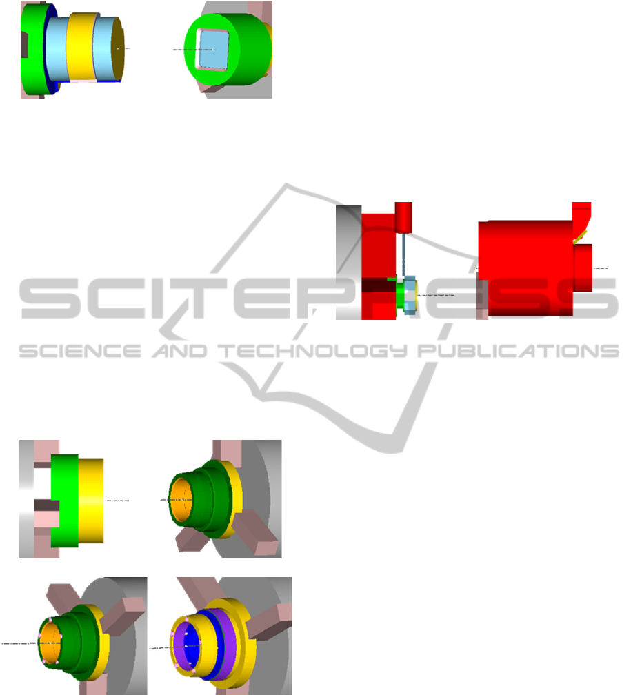
Figure 22: Polar case 1.
Figure 23: Polar case 2.
6.6 Hybrid Turning/Milling/Drilling
In this work, combination of different machining
processes need to be considered, for example, from
turning to milling and then to turning, or from
milling to turning and then to milling. These
changes tend to disrupt the original data structure of
the system. We overcome this problem by recording
the accumulated profile of the turning process,
which can be converted to a solid triangular mesh
anytime. In the subsequent process of milling or
drilling, Boolean operation can be used to obtain the
final geometry. A turning/drilling/turning case is
shown in Figure 24.
(a) the work-piece is turned in positive spindle
(b) move to the sub-spindle, and turn again
(c) the work-piece is drilled
(d) the work-piece is turned again to obtain the final
result
(a)positive spindle(turning) (b)sub-spindle(turning)
(c) sub-spindle(drilling) (d) final results
Figure 24: Different steps of simulation.
6.7 Collision Detection
Collision detection is a very important function in
turn-mill simulation. We can use the collision
detection function to verify whether the NC path is
correct or not, so we can avoid significant damage
because of the collision between the tool and
machine before machining. In this paper, we use
three steps to do collision detection. First, we record
the bounding box of tool when we create the tool
database, then we use an AABB tree to filter
collision components in the simulation. Finally, we
use mesh intersection algorithm to detect collision
components. We display the collision detection by
changing the colour of the collision components to
red to warn the user. Figure 24 (a) shows the
collision result between tool and jaws. Figure 24(b)
shows the collision result between tool and work-
piece.
(a)Tool and jaw
interference
(b) Tool and work-piece
interference
Figure 25: Two different situations of interference.
7 DISCUSSION
Complete turn-mill machining simulation has been
presented in the previous sections. This paper
demonstrates that turn-mill machining simulation is
possible through the integration of 2D Intersection,
Z-map and Boolean algorithms with balanced
efficiency and accuracy. In this section, will discuss
the problems encountered during the simulation
process and their solutions. First, for the turning
simulation, this work achieves the desired result by
2D intersection calculation. The surface of the work-
piece will be deformed according to the intersection
profile. Then, the turned profile is rotated 360
degrees to construct a 3D solid mesh. The result
shows that this method is feasible, robust and highly
efficient. For the milling simulation, this paper
removes materials by the Z-map algorithm. The Z-
map method can provide an excellent simulation
result similar to the Boolean operation but with
better efficiency. Meanwhile, this paper also extends
the Z-map method into polar coordinates system to
simulate turn-mill machining. Furthermore, the
work-piece must be subdivided and then deformed
in order to achieve the simulation of material
removal. It can predict that the system performance
will decrease due to huge polygon data after long
time milling simulation. Thus, polygon merge is
Developmentof3DSimulationSystemforMulti-AxisTurn-MillMachining
723

necessary during the simulation process. Further, the
Z-map can’t perform the drill function to remove
materials due to its algorithm limitation. The
Boolean operation is the only solution to simulate
drilling operation.
The difference set of Boolean can be used to
remove material from the original object.
Theoretically, Boolean operation can produce
precise machining results. However, its drawback is
that Boolean calculation needs higher computation
cost and will decrease performance during
simulation. In addition, coplanar contacts between
the cutter and work-piece are quite common during
the simulation. For the surface-based model
representation, coplanar issue is still a challenge.
8 CONCLUSIONS
The main contribution of this paper is the simulation
of turn-mill machining in 3D with accuracy and
efficiency. Triangular mesh model is used to
represent the cutter and work-piece, including
tooling turret and clamp. The advantage of turn-mill
machining is that it can shorten processing time,
increase productivity, reduce storage space, and
maintain accuracy. The turn-mill process is usually
complicated and involves multiple cutters and
spindles. The danger and cost of collision is high,
therefore accurate and efficient simulation of the
process becomes critical. To achieve this purpose
and balance between efficiency and precision, this
paper proposes a hybrid simulation method by
combining DIP, Z-map and Boolean operations. The
software will determine the appropriate material
removal method according to the NC instructions. In
the simulation processing, in order to check if the
path is correct or not, mesh collision detection
algorithm is used to find out interferences. For the
future work, first, this research will focus on the
improvement of Boolean operation. The efficiency
of Boolean operation is still a bottleneck of
simulation. In addition, the Boolean operators still
need to exclude some special cases such as coplanar
in advance to ensure the success of the simulation.
In the future, this work will also be extended to the
on-line turn-mill simulation/monitor by integrating
the simulation software with a PC-based controller.
REFERENCES
Kerning P., Yuanyuan, X., 2010, “Real-Time Boolean
Operation for NC Machining in Virtual Simulation”,
International Conference on Computer Application
and System Modeling.
Huang, Y. and Oliver, J. H., 1995, “Integrated Simulation,
Error Assessment, and Tool Path Correction for Five-
Axis NC Milling”, Journal of Manufacturing Systems.
Kim, Y. H. and Ko, S. L., 2006, “Improvement of Cutting
Simulation using the Octree Method”, The
International Journal of Advanced Manufacturing
Technology.
Jang, D., Kim, K. and Jung, J., 2000, “Voxel-based Virtual
Multi-axis Machining”, Advanced Manufacturing
Technology.
Chang, K. Y. and Goodman, E. D., 1991, “A Method for
NC Tool Path Interference Detection for A Multi-Axis
Milling System”, ASME Control of Manufacturing
Process.
Lee, S. K. and Ko, S. L., 2002, “Development of
Simulation System for Machining Process using
Enhanced Z Map Model”, Journal of Materials
Processing Technology.
Maeng, S. R., Baek, N., Shin, S. Y., and Choi, B. K., 2003,
“A Z-map Update Method for Linearly Moving Tools”,
Computer-Aided Design.
Maeng, S. R., Baek, N., Shin, S. Y., and Choi, B. K., 2004,
“A fast NC Simulation Method for Circularly Moving
Tools in the Z-map Environment”, Proceedings of the
Geometric Modeling and Processing 04.
Cai, Y., Zhen, L. and Xin, P., 2010, “A Geometrical
Simulation of Ball End Finish Milling Process and Its
Application for the Prediction of Surface Topography”,
Mechanic Automation and Control Engineering.
Tsai, J. P., 2013, “A Modified Z-map Computational
Interpolation Algorithm for Surface Machining
Simulation”, Transactions of the Canadian Society for
Mechanical Engineering.
Tayebi, A, G´omez, P. J, Gonz´alez, D. I, Catedra, F.,
2011, “Boolean Operations Implementation over 3D
Parametric Surfaces to be Included in the Geometrical
module of an Electromagnetic Solver”, Proceedings of
the 5th European Conference on Antennas and
Propagation.
Mei, G. and Tipper, C., 2013, “Simple and Robust
Boolean Operations for Triangulated Surfaces”,
Computational Geometry.
Wang, C. L., 2011, “Approximate Boolean Operations on
Large Polyhedral Solids with Partial Mesh
Reconstruction”, IEEE Transactions on visualization
and computer graphics.
Reqiuicha, A. G., and Voelcker, B., 1985, “Boolean
Operations in Solid Modeling: Boundary Evaluation
and Merging Algorithms”, Proceedings of the IEEE.
Chan, C. K., 2003, “Minimum bounding boxes and
volume decomposition of CAD models”.
Hutter, M. and Fuhrmann, A., 2007, “Optimized
Continuous Collision Detection for Deformable
Triangle Meshes”, Fifth International Conference on
Computer Graphics and Computer Vision.
Curtis, S., Tamstorf, R. and Manocha, D., 2008, “Fast
Collision Detection for Deformable Models using
Representative Triangles”,
ACM I3D.
SIMULTECH2014-4thInternationalConferenceonSimulationandModelingMethodologies,Technologiesand
Applications
724
