
SimuLTE – A Modular System-level Simulator
for LTE/LTE-A Networks based on OMNeT++
Antonio Virdis, Giovanni Stea and Giovanni Nardini
Dipartimento di Ingegneria dell’Informazione, University of Pisa, Pisa, Italy
Keywords: LTE, LTE-Advanced, System-Level Simulator, OMNeT++.
Abstract: This paper describes SimuLTE, an open-source system-level simulator for LTE and LTE-Advanced (LTE-A)
networks. SimuLTE is based on OMNeT++, a well-known, widely-used modular simulation framework, which
offers a high degree of experiment support. As such, it can be seamlessly integrated with all the network-
oriented modules of the OMNeT++ family, such as INET, thus enabling – among other things – credible simu-
lation of end-to-end real-life applications across heterogeneous technologies. We describe the modeling choic-
es and general architecture of the SimuLTE software, with particular emphasis on the MAC and scheduling
functions, and show performance evaluation results obtained using the simulator.
1 INTRODUCTION
The Long-Term Evolution (LTE) of the UMTS
(3GPP-TS 36.300) is the de-facto standard for next-
generation cellular access networks. In an LTE cell, a
base station or eNodeB (eNB) allocates radio re-
sources to a number of User Equipments (UEs), i.e.
handheld devices, laptops or home gateways, using
Orthogonal Frequency Division Multiplexing Access
(OFDMA) in the downlink, and Single-Carrier Fre-
quency Division Multiplexing (SC-FDMA) in the
uplink. On each Transmission Time Interval (TTI,
1ms), a time/frequency frame of resource blocks
(RBs) is allocated to the UEs, in both directions. Each
RB carries a variable amount of bytes to/from an UE,
depending on the selected modulation and coding
scheme. The latter, in turn, is chosen by the eNB
based on the Channel Quality Indicator (CQI) report-
ed by the UE, which measures how the UEs perceive
the channel. The new Release 10, called LTE-
Advanced (LTE-A) (3GPP-TS 36.913), besides
promising larger bandwidths due to spectrum aggre-
gation, envisages different transmission paradigms,
such as Coordinated Multi-Point (CoMP) Scheduling
or device-to-device (d2d) communications.
Resource allocation and management in
LTE/LTE-A is a key performance enabler: carefully
selecting which UEs to target, using which modula-
tion scheme, etc., clearly affects the efficiency of the
system. Moreover, inter-cell interference coordina-
tion, cooperative transmission, antenna selection,
resource partitioning among macro and micro-/pico-
cells, energy efficiency and battery saving schemes,
etc., enable a wealth of declinations of the classical
point-to-multipoint LTE scheduling problem. The
performance evaluation of resource management
schemes for LTE/LTE-A is normally carried out via
simulation. This is because – on one hand – testbeds
are hardly available, especially to the academia, and –
on the other – the entire set of protocols, features and
functions of this standard, and their complex interac-
tions, defy any attempt at unified analytical modeling,
whereas neglecting or abstracting away some aspects
incurs the risk of oversimplification.
Most of the research on LTE/LTE-A is evaluated
via home-brewed “disposable” simulators, which are
never made available to the community. This makes
the claims backed up by such results unverifiable,
hence unauthoritative. In the recent past, more struc-
tured efforts have been made to provide the research
community with reference, open-source simulation
frameworks for LTE/LTE-A. Leaving aside physical-
layer simulators - e.g., (Mehlfuerer et al., 2009), or
(Bouras et al., 2013) - which are outside the scope of
this paper, there are three main contributions. The first
one is (Ikuno et al., 2010), written in MATLAB,
which is limited to the downlink and does not consid-
er some salient aspects of LTE simulation, e.g., realis-
tic traffic generators.
The second one is LTE-Sim (Piro et al., 2011),
written in object-oriented C++. This includes many
59
Virdis A., Stea G. and Nardini G..
SimuLTE – A Modular System-level Simulator for LTE/LTE-A Networks based on OMNeT++.
DOI: 10.5220/0005040000590070
In Proceedings of the 4th International Conference on Simulation and Modeling Methodologies, Technologies and Applications (SIMULTECH-2014),
pages 59-70
ISBN: 978-989-758-038-3
Copyright
c
2014 SCITEPRESS (Science and Technology Publications, Lda.)

more functionalities, such as the uplink, handover,
mobility, UDP and IP protocols, several schedulers
and some traffic generators (e.g., VoIP, CBR, trace-
based, full-buffer). This simulator, however, comes
with some limitations. Hybrid ARQ (H-ARQ) seems
not to be supported. Moreover, scenarios are written
as static C++ functions. Thus, they are hard to verify
for correctness, and they are compiled together with
the simulator. Mixing models, scenarios, and experi-
ment definition in a simulator is hardly desirable from
a software engineering standpoint. The main draw-
back of standalone simulators such as the above two
is that they are costly to extend and not interoperable.
Even granting a state-of-the-art code structure, they
force users to invest an often unreasonable time into
modeling, coding and verifying any extra functionali-
ty, an effort which is seldom reusable. For instance,
the current release of LTE-Sim lacks TCP. The effort
required to develop the code to run a web-browsing
simulation on LTE-Sim (e.g., to back up a claim in a
scientific paper) entails modeling TCP, HTTP, server,
content, and user behavior, and is probably large
enough to discourage most scientists. The same can
be said for the setup of a WiFi-core-LTE simulation
scenario. Moreover, these simulators offer no support
to simulation workflow automation. This includes,
ideally, the ability to define parametric scenarios, to
manage multiple repetitions with independent initial
conditions, to define and collect measures, to effi-
ciently store, retrieve, parse, analyze and plot simula-
tion results, etc. The lack of such instruments (and the
ensuing need to make up for it with home-brewed,
error-prone or however unstructured solutions) is a
major cause of delay and errors in simulation studies,
especially large-scale ones, as shown in (Perrone et
al., 2009, Kurkowski et al., 2005).
A third contribution has been realized within the
framework of ns-3 (ns3-homepage, 2014). ns-3 is
being developed by a large community of scientists
with heterogeneous research interests, and it already
includes a considerable number of network modules
(e.g., WiFi, WiMAX, 802.11s mesh networks, etc.).
The ns-3 LTE simulator (Baldo et al., 2011), hence-
forth ns-3-LTE for want of a better name, is an ongo-
ing effort, which has been designed to allow end-to-
end simulation with realistic traffic models. It in-
cludes both the Radio Access Network and the
Evolved Packet Core. Recently, the SAFE (Simula-
tion Automation Framework for Experiments)
framework has been released, providing functionali-
ties for planning, control and result storage of experi-
ments in ns-3 (Perrone et al., 2012). However, the
SAFE project – still ongoing at the time of writing –
appears to require a non-trivial effort on the user side
to be integrated with ns-3.
Our contribution is a new LTE simulator, called
SimuLTE, which has been developed for the OM-
NeT++ simulation framework (Varga et al., 2008) and
has been released under LGPL at
http://www.simulte.com. We chose OMNeT++ for
several reasons: first, it is a stable, mature and feature-
rich framework, much more so than ns-3. It was re-
leased in 2001, with the explicit goal of automating as
many steps of the simulation workflow as possible, so
as to enable large-scale simulation studies and bridge
the gap between writing down models and getting
credible results. Second, it is perfectly modular,
which made it easy to write all the required code from
scratch, and makes it easy to extend it. Third, it al-
ready includes a large amount of simulation models,
e.g. INET (http://inet.omnetpp.org/), which boasts an
impressive protocol matrix, all the TCP/IP stack,
mobility, wireless technologies, etc.. Thanks again to
the modular structure, this allows users to simulate
mixed scenarios, of which LTE/LTE-A constitutes
only one part, and get a feeling of the true end-to-end
performance of simulated applications. Fourth, OM-
NeT++ has a smooth learning curve: novice users can
exploit graphic interfaces to setup and run fairly com-
plex scenarios in no time, while advanced users may
exploit a structured topology-definition language
(NED, NEtwork Description). Last, but not least, it is
supported by a large and active community of users,
from both academia and networking industries, which
is a guarantee that any setup time invested in learning
the ropes can be amortized over a long future.
SimuLTE simulates the data plane of the LTE Ra-
dio Access Network and Evolved Packet Core. It
consists of over 40,000 lines of code (i.e., roughly
double as many as LTE-Sim, which however also
factors in many extra functionalities, e.g. mobility,
applications, IP/UDP, event queues, etc., which we
instead took from the OMNeT++ kernel and INET).
In this paper, we describe its modeling approach and
show some non-trivial results that can be obtained
with it regarding resource allocation. As for the mod-
eling, besides giving a high-level description, we
focus on the modeling approaches that differ from
those of the other simulators. Specifically, the 3GPP-
compliant H-ARQ functionalities – which are not
described in other simulators – are introduced in some
detail. Furthermore, we detail the scheduling model,
which is based on virtual schedulers, which can be
run concurrently and then be chosen among by an
allocator. As for performance evaluation, we profile
the simulator execution time in several scenarios, we
show how scheduling heuristics for multi-band re-
source allocation problems fare against the optimum,
SIMULTECH2014-4thInternationalConferenceonSimulationandModelingMethodologies,Technologiesand
Applications
60
and we highlight results related to multi-cell environ-
ments which defy analytical modeling.
The rest of the paper is organized as follows. Sec-
tion 2 describes the OMNeT++ framework. Section 3
provides an overview of SimuLTE. We show some
SimuLTE validation in Section 4 and performance
results in Section 5. Finally, Section 6 concludes the
paper and outlines future work.
2 THE OMNeT++ FRAMEWORK
SimuLTE is based on the OMNeT++ simulation
framework, which can be used to model several
things – i.e., not only networks. We focus only on the
aspects of OMNeT++ which are more relevant to
understanding SimuLTE. The interested reader is
referred to http://www.omnetpp.org for more details.
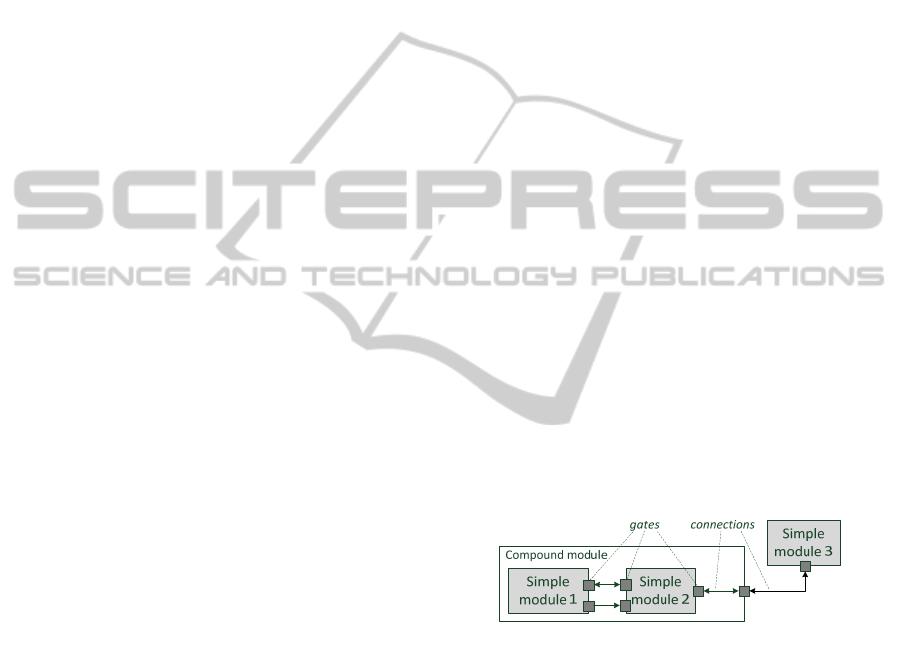
The basic OMNeT++ building blocks are mod-
ules, which can be either simple or compound. Mod-
ules communicate through messages, which are usual-
ly sent and received through a connection linking the
modules’ gates, which act as interfaces. A network is
a particular compound module, with no gates to the
outside world, which sits at the top of the hierarchy.
Connections are characterized by a bit rate, delay and
loss rate, and cannot bypass module hierarchy: with
reference to Figure 1, simple module 3 cannot con-
nect to 2, but must instead pass through the compound
module gate. Simple modules implement model be-
havior. Although each simple module can run as an
independent coroutine, the most common approach is
to provide them with event handlers, which are called
by the simulation kernel when modules receive a
message. Besides handlers, simple modules have an
initialization function and a finalization function,
often used to write results to a file at the end of the
simulation. The kernel includes an event queue,
whose events correspond to messages (including
those a module sends to itself).
OMNeT++ allows one to keep a model’s imple-
mentation, description and parameter values separate.
The implementation (or behavior) is coded in C++.
The description (i.e., gates, connections and parame-
ter definition) is expressed in files written in Network
Description (NED) language. The parameter values
are written in initialization (INI) files. NED is a de-
clarative language, which exploits inheritance and
interfaces, and it is fully convertible (back and forth)
into XML. NED allows one to write parametric to-
pologies, e.g. a ring or tree of variable size. NED files
can be edited both textually and graphically (through
a Graphic User Interface, GUI), switching between
the two views at any time. INI files contain the values
of the parameters that will be used to initialize the
model. For the same parameter, multiple values or
intervals can be specified.
As far as coding is concerned, OMNeT++ comes
with an IDE, derived from Eclipse, which facilitates
debugging. In fact, modules can be inspected, textual
output of single modules can be turned on/off during
execution, and the flow of messages can be visualized
in an animation, all of which occurs automatically.
Events can be logged and displayed on a time chart,
which makes it easy to pinpoint the causes or conse-
quences of any given event.
As for workflow automation, OMNeT++ clearly
separates models (i.e., C++ and NED files) from stud-
ies. Studies are generated from INI files, by automati-
cally making the Cartesian product of all the parame-
ter values and, possibly, generating replicas of the
same instance with different seeds for the random
number generators. Note that the IDE allows one to
launch and manage multiple runs in parallel, exploit-
ing multiple CPUs or cores, so as to reduce the execu-
tion time of a simulation study. Finally, data analysis
is rule-based: the user only needs to specify the files
and folders she wants to extract data from, and the
recipe to filter and/or aggregate data. The IDE auto-
matically updates and re-draws graphs when simula-
tions are rerun or new data become available. The
performance of OMNeT++ has been compared to that
of other simulators, notably ns-3, (Weingartner,
2009). The result is that the two are comparable as for
run time and memory usage, with ns-3 faring margin-
ally better within the limits of the analyzed scenarios.
Figure 1: OMNeT++ module connection.
3 OVERVIEW OF SIMULTE
SimuLTE simulates the data plane of the LTE/LTE-A
Radio Access Network and Evolved Packet Core.
Due to lack of space, we assume that the reader is
familiar with the LTE architecture (a table of acro-
nyms is reported in the Appendix for ease of refer-
ence), and we only describe the RAN modeling. Sim-
uLTE allows simulation of LTE/LTE-A in Frequency
Division Duplexing (FDD) mode, with heterogeneous
eNBs (macro, micro, pico etc.), using omnidirectional
and anisotropic antennas, possibly communicating via
the X2 interface. Realistic channel models, MAC and
SimuLTE-AModularSystem-levelSimulatorforLTE/LTE-ANetworksbasedonOMNeT++
61
resource scheduling in both directions are supported.
In the current release, the Radio Resource Control
(RRC) is not modeled.
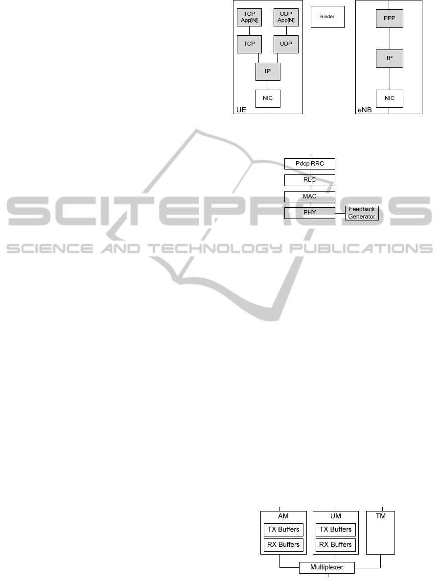
The general structure of the three main nodes is
shown in Figure 2. SimuLTE implements eNBs and
UEs as compound modules. These can be connected
with each other and with other nodes (e.g. routers,
applications, etc.) in order to compose networks. The
Binder module is instead visible by every other node
in the system and stores information about them, such
as references to nodes. It is used, for instance, to lo-
cate the interfering eNBs in order to compute the
inter-cell interference perceived by a UE in its serving
cell. UE and eNB are further composed of modules.
Every module has an associated description file
(.ned) defining its structure, and may have a class
definition file (.cpp, .h) which implements the
module functionalities.
The UDP and TCP modules, taken from the INET
package, implement the respective transport layer
protocols, and connect the LTE stack to TCP/UDP
applications. As Figure 2 shows, TCP and UDP ap-
plications (TCP App and UDP App) are implemented
as vectors of N modules, thus enabling multiple appli-
cations per UE. Each TCP/UDP App represents one
end of a connection, the other end of which may be
located within another UE or anywhere else in the
topology. SimuLTE comes with models of real-life
applications (e.g., VoIP and Video on Demand), but
any other TCP/UDP-based OMNeT++ application
can also be used. The IP module is taken from the
INET package as well. In the UE it connects the Net-
work Interface Card (NIC) to applications that use
TCP or UDP. In the eNB it connects the eNB itself to
other IP peers (e.g., a web server), via PPP (Point-To-
Point Protocol).
The NIC module, whose structure is shown in
Figure 3, implements the LTE stack. It has two con-
nections: one between the UE and the eNB and one
with the LTE IP module. With reference to Figure 3,
each of the NIC submodules on the left side repre-
sents one or more parts of the LTE protocol stack,
which is common to the eNB as well. The only mod-
ule in the UE that has no counterpart in the eNB is the
Feeback Generator, which creates channel feedbacks
that are then managed by the PHY module. In the
following we describe each sub-module with their
related functionalities. We will use downstream and
upstream, respectively, to identify the flow of traffic
from an upper to a lower layer within the same mod-
ule and vice-versa, and downlink and uplink for the
traffic flow from the eNB to the UE and vice-versa.
Figure 2: UE and eNB module structure. Greyed modules
are taken from the INET framework.
Figure 3: NIC module architecture on the UE.
3.1 PDCP-RRC Module
The PDCP-RRC module is the connection point be-
tween the NIC and LTE-IP modules. The PDCP-RRC
module receives data from upper layers in the down-
stream direction and from the RLC layer in the up-
stream. In the first case it performs RObust Header
Compression (ROHC) and assigns/creates the Con-
nection Identifier (CID) that uniquely identifies, to-
gether with the UE ID, a connection in the whole
network. A Logical Connection Identifier (LCID) is
kept for each 4-tuple in the form <sourceAddr,
destAddr, sourcePort, destPort>. When a
packet arrives at the PDCP-RRC module, the correct
LCID is attached to it (if there exists one), otherwise a
new one is created storing the new 4-tuple. Then, the
packet is encapsulated in a PDCP PDU and forwarded
to the proper RLC port, depending on the selected
RLC mode, as described in Section 3.2. In the up-
stream, a packet coming from the RLC is decapsulat-
ed, its header is decompressed and the resulting
PDCP PDU is sent to the upper layer.
Figure 4: RLC module representation.
SIMULTECH2014-4thInternationalConferenceonSimulationandModelingMethodologies,Technologiesand
Applications
62
3.2 RLC Module
The RLC module performs multiplexing and demulti-
plexing of MAC SDUs to/from the MAC layer, im-
plements the three RLC modes Transparent Mode
(TM), Unacknowledged Mode (UM) and Acknowl-
edged Mode (AM) as defined in (3GPP-TS 36.322),
and forwards packets from/to the PDCP-RRC to/from
the proper RLC mode entity. RLC operation is the
same on both the eNB and the UE.
The structure of the RLC module is shown in Fig-
ure 4. There are three different gates connected with
the PDCP-RRC module, one for each RLC mode. The
TM submodule has no buffer, as it forwards packets
transparently, while AM and UM have their own set
of transmission/reception buffers, one for each CID
associated to that RLC mode.
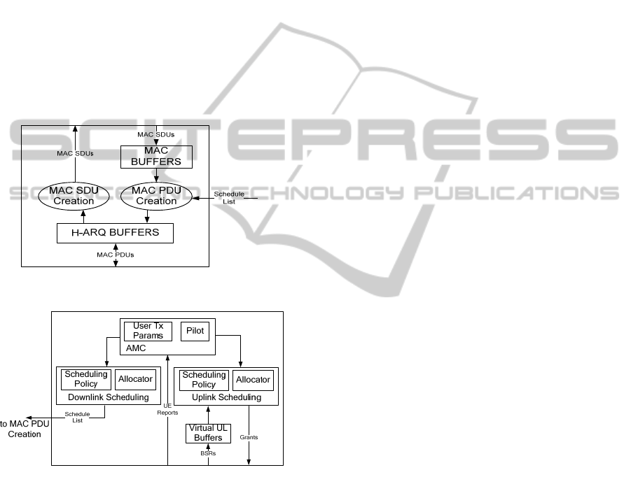
Figure 5: MAC packet flows.
Figure 6: MAC Scheduling Operation.
3.3 MAC Module
The MAC module is where most of the intelligence of
each node resides. Its main tasks are buffering packets
from upper (RLC) and lower layers (PHY), encapsu-
lating MAC SDUs into MAC PDUs and vice-versa,
managing channel feedback, adaptive modulation and
coding (AMC) and scheduling. Those operations are
the same at the UE and the eNB, with scheduling and
channel-feedback management being the only excep-
tions. The high-level structure of the MAC is shown
in Figure 5. In the downstream, MAC SDUs coming
from the RLC layer are stored in MAC Buffers, one
for each CID. On each TTI some connections are
scheduled for transmission, according to the schedule
list composed by the scheduler. MAC SDUs from the
scheduled connections are then encapsulated into
MAC PDUs, which are then stored in the H-ARQ
buffers and forwarded to the physical layer. The de-
tailed structure of H-ARQ buffers will be explained
later on. In the upstream, MAC PDUs coming from
the physical layer are stored into H-ARQ buffers.
They are then checked for correctness, decapsulated
and forwarded to the RLC.
The entities involved in eNB scheduling are
shown in Figure 6. Resource scheduling is performed
at the eNB for both the uplink and the downlink. For
the uplink, decisions are notified to the UEs via grant
messages, i.e., in the current release the Physical
Downlink Control Channel (PDCCH) is not directly
simulated. Each UE reads the grants and decides
which local connection will be able to use the granted
resources, if any. UEs in turn request uplink resources
via the Random Access (RAC) Procedure, which is
again implemented through messages generated by
the MAC module. The Physical Random Access
Channel (PRACH) is not directly simulated. In order
to properly make scheduling decisions, both downlink
and uplink schedulers need the status of user connec-
tions and the channel quality perceived by each UE.
The downlink connection status is inferred directly
from MAC buffers, while in the uplink the status is
inferred from virtual uplink buffers. The latter are
kept synchronized with the real MAC buffers on the
UE side via Buffer Status Reports (BSR), as defined
in (3GPP - TS 36.321), which are control elements
attached to uplink transmissions.
The Adaptive Modulation and Coding (AMC) en-
tity stores channel status information from the UE
reports, deciding (Pilot entity) and storing (User Tx
Params entity) transmission parameters such as mod-
ulation and coderate, and computing the amount of
bytes per resource block for each user based on those
parameters, as defined in (3GPP - TS 36.213).
As far as H-ARQ is concerned, Transmission and
Reception H-ARQ Buffers (from now on TxHbuff and
RxHbuff) store MAC PDUs that are being sent and
received respectively. This means that a MAC PDU is
stored therein until it is received correctly or the max-
imum number of retransmissions is reached. Recep-
tion is notified via H-ARQ feedback messages. H-
ARQ buffers on the eNB maintain MAC PDU infor-
mation for each connected UE in both downlink and
uplink, for each H-ARQ process and for each code-
word (hence, these modules require no modification
to support Single-User MIMO). The general structure
SimuLTE-AModularSystem-levelSimulatorforLTE/LTE-ANetworksbasedonOMNeT++
63
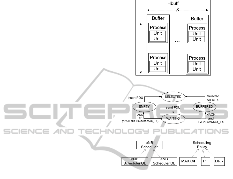
shown in Figure 7 is valid for both Tx- and Rx-
Hbuffs, hence we will use the neutral Hbuff to denote
both. A Hbuff contains K buffers, one for each active
connection to another node. Hence an eNB has as
many buffers as connected UEs in each direction,
whereas a UE has up to one per direction, as it com-
municates directly only with its serving eNB. Each
buffer contains N processes (N=8, usually), one per
H-ARQ process. Finally, each Process contains two
Units, to support SU-MIMO. A Unit contains the
information related to a transmitting/receiving MAC
PDU. The status of the Unit is stored in a different
manner on TX- and RX-buffs as it depends on the
feedback management procedure. The finite state
automata for transmission is represented in Figure 8
(the one for reception is similar, mutatis mutandis).
ACK and NACK are the reception of the correspond-
ing H-ARQ feedback. TxCount is the transmission
counter, increased in the SELECTED state and reset
in the EMPTY one. MAX_TX is the maximum num-
ber of transmissions before discarding a PDU.
The hierarchy of eNB schedulers is shown in the
left part of Figure 9. The eNB Scheduler base class
implements operations that are common to the DL
and UL, such as data structures initialization, alloca-
tion management via the Allocator, and statistics
collection. The two classes eNB Scheduler UL and DL
extend the base class by implementing the
rtxSchedule() method, which manages retrans-
missions. In addiction the eNB Scheduler UL manag-
es RAC requests.
At the beginning of each TTI the eNB prepares a
schedule list in each direction, which shares available
resources among the active connections, according to
a given policy. This is performed by a member of the
eNB Scheduler called Scheduling Policy. Its main
function, schedule(), consists of two steps: first,
the scheduling policy is applied on a set of virtual
connections, without modifying MAC buffers; then
the decisions are stored and passed to the MAC,
which enforces them by fetching the data from its
buffers and constructing the PDUs (see again Figure
6). The scheduling policy builds the schedule lists by
repeatedly polling the Allocator for given amounts of
bytes transmitted at the CQI of the connection being
examined. This allows one to envisage general sched-
ulers, that decide both the priority order of connec-
tions and the amount of data to be scheduled from
each: for instance, schedulers that only serve urgent
data from each connection (instead of attempting to
empty each queue sequentially), or set fixed quanta.
The fact that scheduling occurs in two steps al-
lows a user, among other things, to run multiple
schedulers in parallel, choosing which schedule list to
...
...
N
Figure 7: Common Hbuff structure.
Figure 8: Finite State Automata for Unit status in TX.
Figure 9: eNB schedulers and Sch. Policy hierarchy.
commit among a set of alternatives. The Scheduling
Policy hierarchy is shown in the right part of Figure 9.
To implement a new scheduling policy, a developer
only needs to implement the two steps of the sched-
ule() function. Three well-known scheduling poli-
cies are included in the current release, namely Maxi-
mum Carrier-over-Interference (Max C/I), Propor-
tional Fair (PF), Deficit Round Robin (DRR). Finally,
we observe that scheduling policies may redefine the
rtxSchedule() function. Retransmissions can be
scheduled either at a higher/lower priority than first
transmissions, or jointly with them.
3.4 PHY Module
The PHY module implements functions related to the
physical layer, such as channel feedback computation
and reporting, data transmission and reception, air
channel emulation and control messages handling. It
stores the physical parameters of the node, such as the
transmission power and antenna profile (i.e., omni-
directional or anisotropic). This allows one to define
macro- micro-, pico-eNBs, with different radiation
profiles. Each physical module on the eNB and the
SIMULTECH2014-4thInternationalConferenceonSimulationandModelingMethodologies,Technologiesand
Applications
64

UE has an associated Channel Model C++ class that
represents the physical channel as perceived by the
node itself. The Channel Model is an interface that
defines two main functions: getSINR(), which
returns the Signal to Interference plus Noise Ratio
(SINR), and error(), which checks if a packet has
been corrupted. We describe the current implementa-
tion of the channel model later on, but one can easily
implement its own model by implementing the Chan-
nel Model interface.
On the UE side, some tasks related to physical
layer procedures are performed by an independent
Feedback Generator module. This module generates
channel feedback (i.e., CQIs), which can be config-
ured to be periodic or aperiodic. Furthermore, CQIs
can be either wideband or per-sub-band: in the latter
case, the user can configure the number of sub-bands
and of reported CQIs. The feedback generation pro-
cess exploits the function provided by the Channel
Model interface. Note that the physical LTE channels,
such as the Physical Downlink Control Channel
(PDCCH), Physical Uplink Control Channel
(PUCCH) and Physical Random Access Channel
(PRACH) are not modeled down to the level of
OFDM symbols, to keep both memory and CPU
usage limited. Their functionalities are instead im-
plemented via control messages sent between the eNB
and UE nodes. Any limitation of those channels, (e.g.,
on the maximum number of UEs that can be sched-
uled simultaneously on the PDCCH), can nevertheless
be emulated by imposing constraints on the messages
themselves.
In the downstream, MAC PDUs are received from
the MAC layer and encapsulated in an Air Frame
packet. Packets are marked with a Type, i.e. data or
control, then they are directly sent to their destination
module, selected according to the control information
attached to the packet. In the upstream, a received Air
Frame packet is selectively processed depending on
its type: control packets are directly forwarded to the
upper layer (assuming correct reception), whereas
data packets are tested against the error() function
of the Channel Model before being marked and sent
to the upper layer.
Our implementation of the Channel Model inter-
face is called Realistic Channel Model. The SINR is
computed as
eNB i
RX RX
i
SINR P P N
, where
eNB
RX
P
is the power received from the serving eNB,
i
R
X
P
is
the power received from the interfering eNB i, N is
the Gaussian noise. Furthermore,
R
X
P
is computed as
RX TX
PPPlossFS
, where
TX
P
is the transmis-
sion power, Ploss is the path loss due to the eNB-UE
distance (which depends on the frequency), and F and
S are the attenuation due to fast and slow fading re-
spectively (Jakes, 1975). The above operations are
performed within the getSINR(), on a per-RB
basis. This allows one to simulate the effects of inter-
ference on every single RB, e.g. taking into account
the transmissions from neighboring eNBs, so as to
evaluate LTE-A interference-coordination mechanism
such as the Enhanced inter-cell interference coordina-
tion (eICIC) or Coordinated MultiPoint (CoMP). The
error() function compares the CQI used for
transmitting a packet with the one computed at the
moment of reception. An error probability
err
P
is then
obtained by using realistic BLER curves and the two
previously computed CQIs. A uniform random varia-
ble
0,1X
is sampled and the packet is assumed to
be corrupted if
err
XP
, and correct otherwise.
The choice of the channel model usually arises
strong feelings among scientists and practitioners in
wireless networks. For this reason, besides proposing
one, we took care of implementing it in an easily
modifiable way. Modifications can be done in either
of the following ways:
extend the base LteChannelModel class, and
specifically implement the two functions
getSINR()and error(). This requires some
work, but allows maximum flexibility.
Modify our Realistic Channel Model, and specif-
ically the functions for computing pathloss, fad-
ing and shadowing. This requires minimal modi-
fications, at the price of less flexibility.
Note that, whichever the choice, the rest of the
code is obviously unaffected.
4 VALIDATION
Validating the tons of data produced by a simulator is
a very common problem. One possible approach is to
compare these values against measurement obtained
from real systems. Unfortunately, to the best of our
knowledge, none of these measurements are publicly
available. Another possible solution, as suggested in
(Zhou
et al., 2013), is to compare simulation results
with theoretical ones obtained in simple reference
scenarios. We thus choose a single cell in two scenar-
ios: a single-user one (scenario I) and a multi-user
one (scenario II). In both cases UEs are static and
measurements are made at distances to the eNB rang-
ing from 500 to 2000 meters. In scenario II UEs are
placed within a 50m-radius circle centred at the speci-
fied distance. The main simulation parameters are
described in Table 1.
SimuLTE-AModularSystem-levelSimulatorforLTE/LTE-ANetworksbasedonOMNeT++
65
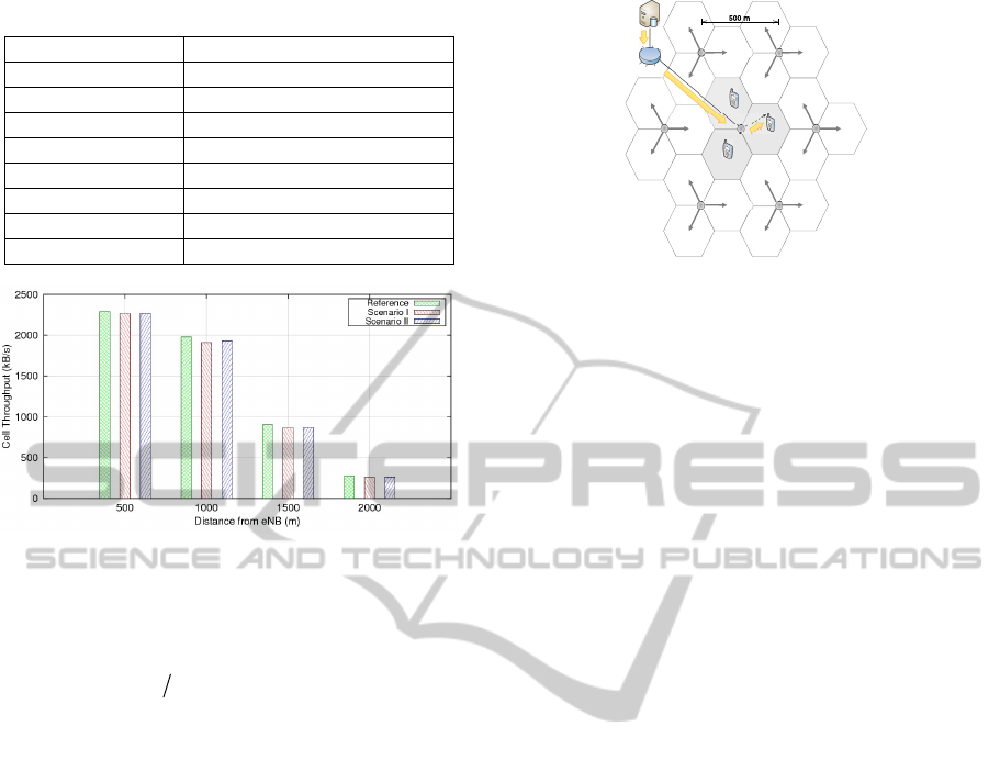
Table 1: Simulation parameters.
Parameter Value
N
PRB
25
Pathloss model ITU-R, Rural Macro
Mobility model Stationary (OMNeT++ model)
eNB Tx Power 30 dBm
Noise figure 5 dB
Cable loss 2 dB
Distance eNB – UE 500, 1000, 1500, 2000 m
Simulation time 2 seconds
Figure 10: Cell Throughtput for Scenario I and Scenario II
compared against theoretical reference throughput.
We compare the throughput of the simulated scenari-
os against a reference throughput obtained as
(, )
PRB
Tpt S MCS N (Zhou et al., 2013) where
is
the duration of a TTI (i.e. 1ms),
(, )
P
RB
SMCSN is the
transport block size for the measured CQI and for
N
PRB
physical resource blocks.
As we show in Figure 10, simulation results match
the reference ones, in both scenarios. Note that the
results obtained with distances greater than 500m are
not directly comparable with the ones of the above
work, as the two pathloss models are different.
5 PERFORMANCE EVALUATION
This section presents three contribution. First, we
show how the simulation times varies with the num-
ber of UEs and cells and with the traffic profile. Sec-
ond, we show that inter-cell interference increases the
number of allocated RBs in a cell in a way which
analytical formulas fail to predict. Finally, we formu-
late the MaxC/I scheduling problem in a multi-band
setting as an optimization problem, we show to solve
it optimally by interfacing SimuLTE and CPLEX, and
we use it to benchmark a simple heuristic.
Figure 11: Simulation scenario.
5.1 Profiling of Execution Time
We setup a scenario with a varying number of UEs
and cells. eNBs use anisotropic antennas, radiating at
120° angles and transmitting at 46dBm, and employ
MaxC/I scheduling. The simulation scenario is shown
in Figure 11, where each circle represents a cluster of
three co-located cells. CQIs are wideband and report-
ed periodically. The UM RLC is employed, and the
MAC fragment is set to 20 bytes. The overall amount
of available RBs is 50. UEs are uniformly distributed
among cells and receive VoIP traffic (40-byte applica-
tion packets on each 20ms, with alternated talkspurts
and silences), which is generated by a server and
forwarded to the eNBs through a router. 20s of the
above system are simulated on an Intel(R) Core(TM)
i7 CPU at 2.80 GHz, with 8 Gb of RAM, a Linux
Ubuntu 12.04 operating system, and OMNeT++ ver-
sion 4.2.2. Each run is repeated five times in inde-
pendent conditions. 95% intervals are displayed un-
less negligible.
Figure 12 reports the running time for three, nine
and 21 cells. The latter depends almost linearly on the
number of UEs in all cases. Increasing the number of
cells influences the overall running time, as compu-
ting interference requires more operations.
In the scenario with nine cells, Figure 13 shows
how the simulation time depends on the traffic pro-
file: we vary the packet size and the period, while
keeping the same application-layer bitrate,. However,
Figure 14 shows that the MAC-level per-UE bitrate is
quite different, due to the protocol overheads. In par-
ticular, the MAC PDU size is 33 bytes larger than the
application packet (header compression is not used).
In Figure 13, bottom, mid and top markers on each
curve are for 30, 60, and 90 UEs, respectively. For the
same MAC-layer offered load (i.e., the same abscis-
sa), smaller packets sizes require shorter simulation
times. However, for the same number of UEs (i.e., the
same group of markers), the simulation time depends
on the number of transmitted packets, hence a smaller
SIMULTECH2014-4thInternationalConferenceonSimulationandModelingMethodologies,Technologiesand
Applications
66
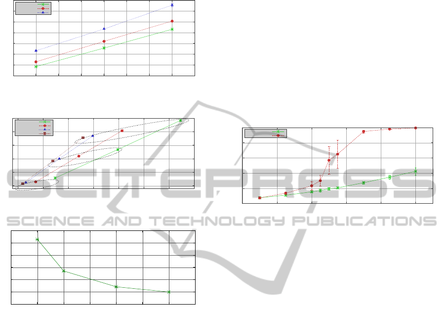
packet size (i.e., more packets per unit of time) im-
plies longer simulation times.
100
200
300
400
500
600
700
800
20 30 40 50 60 70 80 90 100
Time [s]
Number of UEs
3 cells
9 cells
21 cells
Figure 12: Execution time with varying number of cells.
200
300
400
500
600
700
500 1000 1500 2000 2500 3000 3500 4000
Time [s]
Offered Load [Kbps]
20 Bytes
40 Bytes
80 Bytes
120 Bytes
Figure 13: Execution time with varying offered load.
15
20
25
30
35
40
45
0 20 40 60 80 100 120 140
Bitrate Per UE [Kbps]
Packet Size [B]
Figure 14: Bitrate per UE at MAC level.
5.2 Inter-cell Interference
SimuLTE allows in-depth analysis of the effects of
the inter-cell interference. We consider three co-
located cells as in Figure 13. UEs receive CBR traffic
at a rate of 0.2 Mbps. Figure 15 reports the average
number of RBs allocated by a cell. We compare the
results with those obtained by using the formula in
(Fantini et al., 2011), using the same channel model
in both cases. The formula evaluates the interference
based on the probability that two cells use the same
RB, given the amount of RBs allocated by the two
cells and assuming that each cell picks its RBs at
random in the frame. Since the interference depends
on the allocated RBs and vice versa, the formula is
updated until it reaches a steady state. We note that
there is a point (at 65-70 UEs) where the simulative
curve has a step. This happens because the more a cell
fills its own frame, the more it generates interference
on UEs of neighbouring cells, which in turn report
lower CQIs. Accordingly, neighbouring cells need to
allocate more RBs to serve their UEs, thus producing
additional interference that further decreases CQIs
and causes retransmissions. Moreover, transmissions
may occur simultaneously on RBs with low and high
interference. Since wideband CQIs are used, high-
interference RBs may be corrupted, causing retrans-
mission, hence even more allocated RBs. At low
loads, the system is still able to satisfy the additional
requests, whereas at high loads this results in a posi-
tive feedback that rapidly drives the system towards
saturation. This effect cannot be observed using the
analytical formula because it does not account for the
impact of errors and retransmissions.
0
10
20
30
40
50
20 40 60 80 100 120
Avg Allocated RBs
Number of UEs
Baseline
SimuLTE
Figure 15: Average allocated RBs per cell.
5.3 Multi-band Scheduling
Many resource allocation problems in LTE/LTE-A
can be formulated as optimization problems. Hereaf-
ter, we describe a typical one, and we show how to
interface SimuLTE with optimization solver CPLEX
to solve it, believing this to be useful to researchers
working in this area, for both the results and the way
we obtained them.
MaxC/I scheduling is a relatively simple problem
if we assume wideband CQIs and a number of trans-
mitted bytes which is linear with the number of allo-
cated RBs, with the CQI representing the line slope.
In fact, in this case, all it takes to obtain the maxi-
mum throughput is to allocate enough RBs to empty
the queue of each UE, in decreasing order of CQI
(taking some extra care when padding is involved).
Therefore, MaxC/I scheduling can be obtained at a
complexity of
logON N
, N being the number of
UEs. When per-sub-band CQI are used, however,
obtaining the maximum throughput becomes an NP-
hard problem, as shown in (Accongiagioco et al.,
2013), hence some heuristics are used to obtain
suboptimal solutions. Recall that a UE can use one
CQI in a TTI (typically, the minimum of all the CQIs
in the sub-bands where it is allocated some RBs). The
maximum throughput problem can be formulated as
follows:
SimuLTE-AModularSystem-levelSimulatorforLTE/LTE-ANetworksbasedonOMNeT++
67

,
11
,
11
,,max
,,
,
1
,,
max
..
1
1
,
,
0,1 , ,
NM
iiji
ij
MM
iijii
jj
ii
iij ij
ij ij
N
ij j
i
ii
ij ij
rxp
s
trxpQii
p
riii
rCQI b CQI i iii
x
bijiv
x
Bjv
rp i vi
bx ijvii
(1)
where M is the number of sub-bands, each one of
which having
j
B
RBs.
i
r
is the rate that will be used
by UE i (assumed to be a number of bytes per RB),
,ij
CQI
is the CQI of UE i in sub-band j (translated to
a number of bytes per RB as well),
i
p
and
i
Q
are the
padding and queue length for UE i.
,ij
b
is a binary
variable that is equal to 1 if UE i is allocated RBs in
sub-band j, and
,ij
x
is the number of RBs that it has
allocated in that sub-band.
The above one is a mixed integer-non-linear prob-
lem, which can be linearized using standard enumera-
tion techniques and solved through CPLEX (which
only solves linear problems). Therefore, we can use
the optimal solutions to benchmark heuristics, provid-
ed that we interface SimuLTE and CPLEX. There are
two ways to do so: one is to use its C++ API, which
requires integrating it into Eclipse and learning to use
it, both being non-trivial. The other, which we chose,
is to manage files via tmpfs, i.e., save files in vola-
tile memory: while this is less efficient, it only re-
quires one to be able to write down a scheduling prob-
lem in the LP file format used by CPLEX (which is
very intuitive) and to write a parser for SOL CPLEX
output solution files, which are XML-based.
At each TTI, we do the following: first we obtain
the constants, i.e., queue size, per-sub-band CQIs, etc.
Then, we generate an LP file describing the linearized
problem. The problem is then solved by invoking
CPLEX with the LP file as an input. The resulting
SOL file can be easily parsed via xml-related func-
tions given by the omnetpp environment. Figure 16
shows a snippet of the output file that defines the final
allocation: each line specifies the name of a variable
(x
i_j
, in this case) and its value, i.e. the number of RBs
allocated to user i within sub-band j. Finally the allo-
cation is enforced in the simulated system and the rest
of the operations for the TTI are executed.
The multi-band MaxC/I heuristic that we choose
to benchmark is the following: we sort all UEs by
decreasing sum of per-sub-band CQIs, and we allo-
cate enough RBs to empty their queue (as if multiple
CQIs could be used simultaneously). Then we use the
minimum CQI among the selected sub-bands. We
compare the above solutions in a scenario with six
RBs, a number of UEs ranging from 10 to 75, and
VoIP traffic. Both solutions achieve the same
throughput, since the system is still far from satura-
tion conditions, but the heuristics uses up to 30%
more RBs, as shown in Figure 17.
Figure 16: Snippet of CPLEX XML output file.
0
0.5
1
1.5
2
2.5
3
3.5
4
4.5
5
10 25 50 75
RBs
Number of UEs per cell
A
vg Allocated RBs per cell
Heuristic
Optimum
Figure 17: RB occupancy comparison between the heuristic
and optimum solutions.
6 CONCLUSIONS
This paper described SimuLTE, an open-source
LTE/LTE-A simulator based on the OMNeT++
framework. The current release supports the data
plane of the radio access network, with a full protocol
stack, a realistic physical layer and scheduling capa-
bilities. We have described the modeling approach in
detail, especially focusing on the MAC and resource
allocation models. Moreover, we have shown some
examples of performance evaluation that can be ob-
tained through SimuLTE.
There are several directions in which this work
can be extended, most of which are being pursued at
the time of writing:
The initial validation provided in Section 4 is to
be expanded. Our contributions in this direction
will be presented in future works.
[…]
<variable name="x4_1" […]value="1"/>
<variable name="x4_2" […]value="1"/>
<variable name="x4_3" […]value="1"/>
<variable name="x4_4" […]value="1"/>
<variable name="x4_5" […]value="1"/>
<variable name="x5_0" […]value="1"/>
[…]
SIMULTECH2014-4thInternationalConferenceonSimulationandModelingMethodologies,Technologiesand
Applications
68

As anticipated in the Introduction, there are other
LTE simulators available for the public domain.
A comparison of SimuLTE against these is on
the agenda. We expect this comparison to rein-
force validation, to provide insight regarding the
different features and capabilities of the simula-
tors, and to benchmark their efficiency.
The LTE-A technology is evolving, and Sim-
uLTE evolves accordingly. We are in fact adding
several models to SimuLTE. Among the planned
future releases we mention support to device-to-
device (D2D) communications and Coordinated
Multi-Point transmission (CoMP).
ACKNOWLEDGEMENTS
The authors would like to thank all those who have
contributed to the SimuLTE code as former students
of the University of Pisa, namely Matteo Maria An-
dreozzi of NVIDIA, UK, Daniele Migliorini of Aru-
ba, Italy, Giovanni Accongiagioco of CNR, Italy,
Generoso Pagano of INRIA Grenoble Rhône-Alpes,
France, Vincenzo Maria Pii of ZHAW, Switzerland.
They also would like to thank Andras Varga, Rudolf
Hornig, Levente Mészáros and Gábor Tabi of Sim-
ulCraft for support and discussion on the code.
REFERENCES
3GPP - TS 36.300 Evolved Universal Terrestrial Radio
Access (E-UTRA) and Evolved Universal Terrestrial
Radio Access Network (E-UTRAN); Overall descrip-
tion; Stage 2.
3GPP - TS 36.913 Requirements for further advancements
for Evolved Universal Terrestrial Radio Access (E-
UTRA) (LTE-Advanced).
Varga, A. and Hornig, R. (2008), "An overview of the
OMNeT++ simulation environment", in Proc. SI-
MUTools '08, Marseille, France, March 2008.
Mehlfuerer, C., Wrulich, M., Ikuno, J.C., Bosanska D.,
Rupp, M., “Simulating the long term evolution physical
layer”, in Proc. 17th EUSIPCO, Glasgow, UK, 2009.
Ikuno, J.C. , Wrulich, M., Rupp, M., “System level simula-
tion of LTE networks”, in Proc. of IEEE VTC-Spring,
Taipei, Taiwan, May 2010, pp. 1-5.
Piro, G. , Grieco, L. A., Boggia, G., Capozzi F., Camarda,
P., “Simulating LTE Cellular Systems: An Open-Source
Framework”, IEEE Trans. on Vehicular Technology,
60:(2), Feb. 2011.
Ns-3 homepage, available at http://www.nsnam.org/ [ac-
cessed 2014/04]
Baldo, N., Miozzo, M., Requena-Esteso, M., Nin-Guerrero,
J., “An Open Source Product-Oriented LTE Network
Simulator based on ns-3”, in Proc. of ACM
MSWiM’11, Miami, US, Nov. 2011.
Perrone, L. F., Cicconetti, C., Stea, G., Ward, B., "On the
Automation of Computer Network Simulators", in Proc.
of SIMUTools’09, Rome, Italy, March 3-5, 2009.
3GPP - TS 36.322 Radio Link Control (RLC) protocol
specification.
Weingartner, E., Vom Lehn, H., Wehrle, K., “A perfor-
mance comparison of recent network simulators”, in
Proc. of IEEE ICC’09, June 14-18, Dresden, DE, 2009.
3GPP - TS 36.321 Medium Access Control (MAC) protocol
specification.
3GPP - TS 36.213 Physical layer procedures.
Kurkowski, S., Camp, T., Colagrosso, M., “MANET Simu-
lation Studies: The Incredibles”. ACM SIGMOBILE
MCCR 9 (4): 50–61, 2005.
Jakes, W.C., Microwave Mobile Communications, Wiley,
1975.
Accongiagioco, G., Andreozzi, M.M., Migliorini, D., Stea,
G., “Throughput-optimal Resource Allocation in LTE-
Advanced with Distributed Antennas” Computer Net-
works, vol. 57(2013), pp. 3997-4009.
Fantini, R., Sabella, D., Caretti, M., “An E3F based assess-
ment of Energy Efficiency of Relay Nodes in LTE-
Advanced networks”, in Proc. IEEE PIMRC 2011, 11-
14 Sept. 2011, pp.182-186.
Perrone, L.F., Main, C., Ward, B.C., “SAFE: Simulation
Automation Framework for Experiments”, in Proc. of
IEEE WSC 2012, Berlin, DE, 9-12 Dec. 2012.
Bouras, C., Diles, G., Kokkinos, V., Kontodimas, K., Pa-
pazois , A., “A Simulation Framework for Evaluating
Interference Mitigation Techniques in Heterogeneous
Cellurar Environments”, Wireless Personal Communi-
cations, Springer-Verlag, 2013.
Zhou, D., Baldo, N., Miozzo, M., “Implementation and
Validation of LTE Downlink Schedulers for ns-3”, in
Proc. SIMUTools '13, Cannes, France, March 3013.
APPENDIX
Table 2: LTE-related acronyms used in the paper.
Acronym Definition
AM Acknowledged RLC mode
BLER Block Error Rate
BSR Buffer Status Report
CID Connection identifier
CoMP Coordinated Multi-Point
CQI Channel Quality Indicator
DL Downlink
DRR Deficit Round Robin
eNB Evolved Node-B
EPC Evolved Packet Core
e-ICIC Enhanced Inter-Cell Interf. Cancellation
FDD Frequency Division Duplexing
H-ARQ Hybrid Automatic Repeat reQuest
LCID Logical Connection identifier
SimuLTE-AModularSystem-levelSimulatorforLTE/LTE-ANetworksbasedonOMNeT++
69

Table 2: LTE-related acronyms used in the paper (Cont.).
Acronym Definition
LTE Long-term Evolution
LTE-A Long-term Evolution Advanced
MaxC/I Maximum Carrier over Interference
PDCCH Physical Downlink Control CHannel
PDCP Packet Data Convergence Protocol
PDU Protocol Data Unit
PF Proportional Fair
PRACH Physical Random Access CHannel
RAC Random Access Procedure
RB Resource Block
RLC Radio Link Control
RRC Radio Resource Control
RU Remote Unit
SDU Service Data Unit
SU-MIMO Single-User MIMO
TM Transparent RLC mode
TTI Transmission Time Interval
UE User Equipment
UL Uplink
UM Unacknowledged RLC mode
SIMULTECH2014-4thInternationalConferenceonSimulationandModelingMethodologies,Technologiesand
Applications
70
