
Robotic Grasping and Manipulation Controller Framework
Architecture Redevelopment
Pavel Dzitac
1
, Abdul Md Mazid
2
, Guy Littlefair
1
and Ashwin Polishetty
1
1
School of Engineering, Deakin University, Geelong, Australia
2
School of Engineering and Technology , Central Queensland University, Rockhampton, Australia
Keywords: Object Manipulation, Controller Framework, Slippage Control.
Abstract: This paper details the further improvements obtained by redesigning a previously offered Manipulation
Controller Framework to provide support to an innovative, friction-based object slippage detection strategy
employed by the robotic object manipulator. This upgraded Manipulation Controller Framework includes
improved slippage detection functionality and a streamlined architecture designed to improve controller
robustness, reliability and speed. Improvements include enhancements to object slippage detection strategy,
the removal of the decision making module and integration of its functionality into the Motion Planner, and
the stream-lining of the Motion Planner to improve its effectiveness. It is anticipated that this work will be
useful to researchers developing integrated robot controller architectures and slippage control.
1 INTRODUCTION
This paper presents an improved robotic
Manipulation Controller Framework architecture
(Figure 1) that was offered in an earlier paper
(Dzitac and Mazid, 2012).
Literature survey revealed that various
framework architectures have been proposed by
other researchers. Khalil and Payeur, 2007, proposed
and integrated framework based on earlier work by
Howard and Bekey, 2000. This framework is
intended to facilitate interaction with deformable
objects under robot vision and tactile sensing
guidance. Prats et al, 2009, proposed a control
framework for vision-tactile force and physical robot
interaction. Wettels et al, 2009, proposed a grasp
control algorithm that uses a Kalman filter to
provide a robust tangential force feedback signal
from the gripper during object manipulation.
These are just some of the object manipulation
control frameworks and algorithms proposed by
researchers that strive to develop architectures with
ever better functionality and effectiveness.
The controller framework presented in this paper
is not an attempt to develop the ideal framework, but
rather to improve the performance and usefulness of
the proposed framework architecture, and hopefully
contribute with a good idea to the research effort in
this area of robotics.
The highest priority task in this project has been
to improve the effectiveness of the slippage
detection and slippage prevention function. This has
been achieved mainly by redeveloping the sensor
fusion function to help enhance the effectiveness of
the slippage detection strategy. Overall, this resulted
in an improved ability to predict slippage, and also
to differentiate between small and large slippages.
The decision making module has been merged
into the motion planning module, and therefore
unnecessary redundancy and complexity has been
eliminated.
The control module interactions that were not
adding value to controller performance have also
been discarded.
2 MANIPULATION
CONTROLLER FRAMEWORK
The most challenging part of developing the robotic
manipulation controller framework for this project
has been found to be the development of an effective
and streamlined architecture that eliminates
unnecessary control functions, data processing and
interaction redundancies, but at the same time
provides the essential information and interactions to
ensure fast and effective control.
368
Dzitac P., Mazid A., Littlefair G. and Polishetty A..
Robotic Grasping and Manipulation Controller Framework - Architecture Redevelopment.
DOI: 10.5220/0005043903680373
In Proceedings of the 11th International Conference on Informatics in Control, Automation and Robotics (ICINCO-2014), pages 368-373
ISBN: 978-989-758-040-6
Copyright
c
2014 SCITEPRESS (Science and Technology Publications, Lda.)
Based on authors’ experience gained during
experimentation with various versions of the
controller framework, it can be stated that the
manipulation controller framework architecture
plays the most important role in the ability of the
controller to perform object grasping and
manipulation tasks.
In general, the various control functions can be
readily modified, especially when their output has
no significant impact on other functions. The
controller architecture, on the other hand, defines the
hierarchies of control functions and their
interactions at system level; it is the “strategic and
tactical manager” of the controller. Get this wrong
and the controller will be close to useless. This is
why researchers invest significant effort into the
development of robust controller architectures that
incorporate the necessary functionality for safe and
reliable robotic object grasping and manipulation.
This controller framework architecture has been
developed in the following sequence:
a. Establish the final control capabilities that the
controller needs, such as the Motion Path that
the robot has to follow, motion Speed and arm
joint Force necessary for robot movement;
b. Establish the major inputs needed to provide the
necessary data (such as Grasp Data and Object
Data) required to achieve these control tasks;
c. Establish the sources of this data, such as
Decision Engine and Slippage Detection
functions;
d. Group the data sources into major functions,
such as Motion Planner and Motion Controller
to remove unnecessary detail and simplify the
interactions between major controller modules;
e. Establish feedback loops for functions that
require feedback for reasonable decision
making;
f. Determine the physical sensors needed to
provide the required data on which decisions are
going to be based;
g. Rationalise the data sources, streamline the
interactions between functions and simplify the
framework to improve robustness.
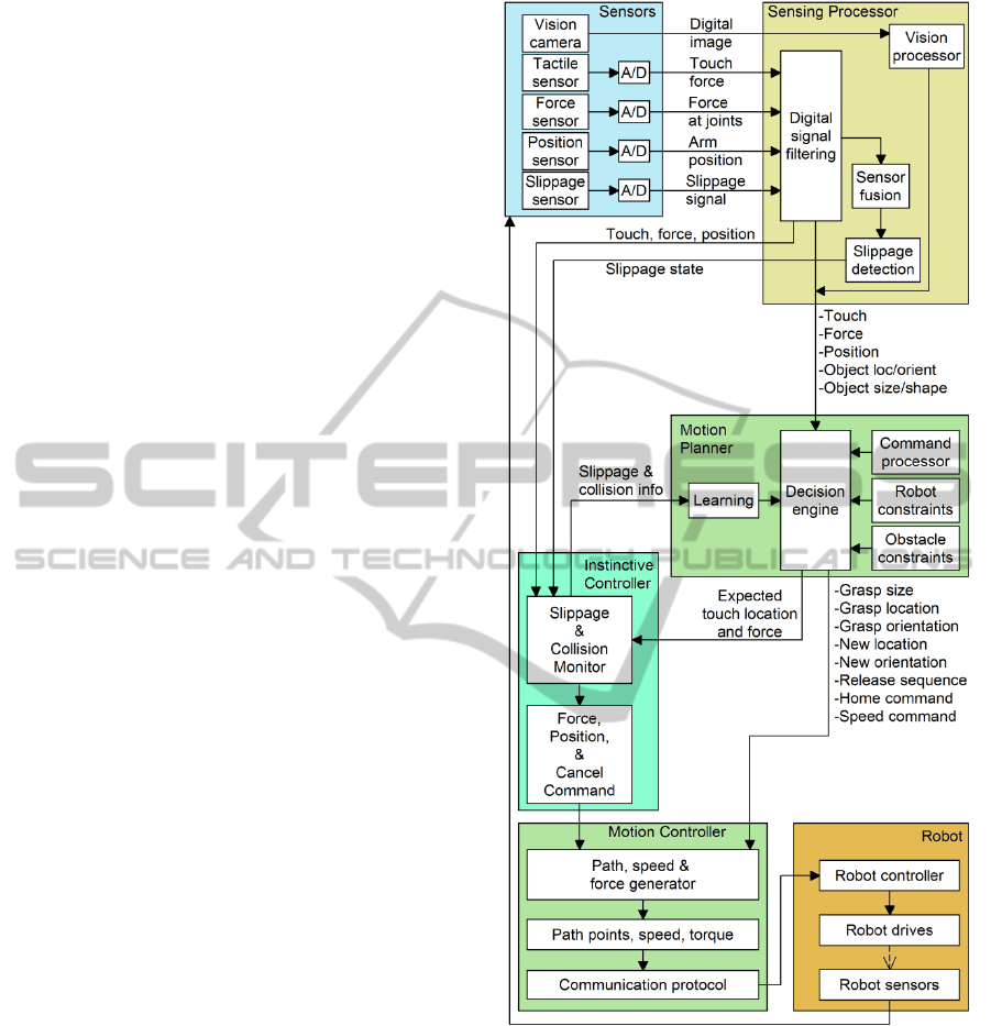
In order to facilitate understanding of the overall
object grasping and manipulation approach, the
robotic manipulation controller framework and its
functional modules (Figure 1), including the Sensing
Processor, the Instinctive Controller, the Motion
Planner and the Motion Controller are presented
using figures and short descriptions. The slippage
sensing approach used is presented in more detail.
Figure 1: The proposed grasp and manipulation controller
framework.
The “Sensors” used in the manipulation controller
framework are a digital camera used for object
detection, tactile forces (grasp force from gripper
motor current and tangential force from gripper shaft
torque), arm joint force sensing (from joint motor
current), arm position and an innovative friction-
based slippage sensor.
The “Robot” is a typical robot capable of
accepting and executing motion commands.
RoboticGraspingandManipulationControllerFramework-ArchitectureRedevelopment
369
2.1 Sensing Processor
The Sensing Processor module (Refer to Figure 1) is
based on mathematical and logic control models
designed to:
a. Process the vision feedback and convert it into
object location, orientation, size and shape
information;
b. Use digital filtering to filter the digitized sensor
signals and convert them into stable feedback
signals required by the control modules;
c. Use sensor fusion at system level to improve
slippage detection reliability and enhance
slippage information detail.
The vision feedback has been implemented at
basic level that is sufficient to allow the controller to
detect the object, determine its location, orientation
and size, and plan the motion necessary to grasp and
relocate the object to a new location.
Digital filtering used is based on a running
average of 21 values similar to that presented by
Smith, 1999.
Sensor fusion has been implemented at system
level and designed to support the slippage detection
function within the sensing processor module.
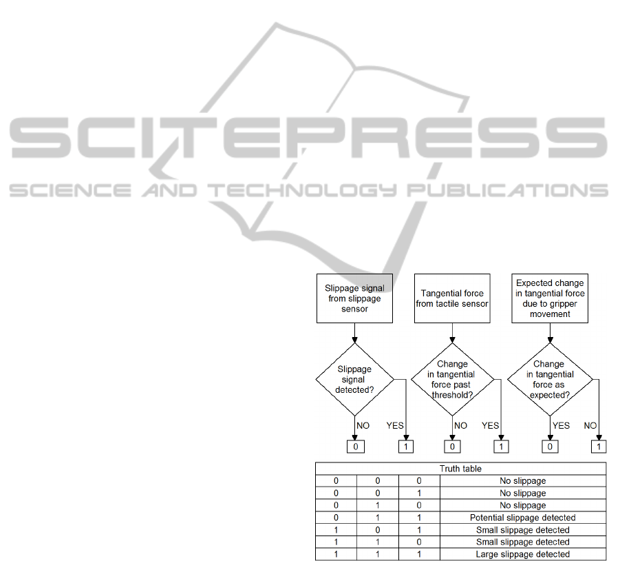
2.1.1 Sensor Fusion for Slippage Detection
Initially sensor fusion for slippage detection has
been based on the tangential force sensor and vision
feedback. However this proved to be difficult due to
the need for complex, real time object position
feedback from the slow vision camera.
The current sensor fusion (Figure 2) is based on
feedback from a slippage sensor and a tangential
force sensor. The slippage sensor used has an
inherent slippage detection capability, rather than
derived slippage detection based on micro-vibration.
The tangential force sensing is based on the torque
developed by the manipulated object on the
gripper’s roller-shaft pair (Dzitac and Mazid, 2012).
A major advantage of this redeveloped slippage
detection strategy is the ability to provide detailed
slippage information including “potential” slippage
and slippage magnitude.
Potential slippage is defined here as slippage that
has not yet been detected by the dedicated slippage
sensor, however based on tangential force changes
relative to the current grasp force, slippage is about
to occur because there is barely any grasp force
safety margin left.
The grasp force safety margin threshold level has
been based on the estimated static coefficient of
friction at the gripper-object interface. The grasp
force safety margin is adjusted during object
manipulation based on feedback from the dedicated
slippage sensor.
In this controller the magnitude of the grasp
force safety margin F
SM
is estimated as
F
SM
= µ
s
F - F
t
(1)
where F is the grasp force, F
t
is the tangential force
on the gripper (force that tends to slide the object out
of the gripper) developped by the mass of the
manipulated object when no slippage takes place,
and the static coefficient of friction µ
s
is estimated as
µ
s
= F
start
/ F
stop
(2)
where F
start
is the grasp force value at the point of
impending slippage and F
stop
is the grasp force value
at the point where slippage stops. The slippage start
and stop points are provided by the dedicated
slippage sensor during object manipulation.
The minimum grasp force safety margin F
SM
in
this controller is limited such that
0.05 F
t
< F
SM
< 0.15 F
t
(3)
Equation 1 allows the controller to adjust the grasp
force safety margin within the limits of equatiom 3
in order to prevent slippage and avoid excessive
grasp forces.
Figure 2: Sensor fusion for slippage detection.
2.2 Instinctive Controller
The Instinctive Controller module (Figure 3) is a
type of reactive controller that has been designed to:
a. Bypass the slow control actions of Motion
Planner, and therefore generate fast, instinct-
ICINCO2014-11thInternationalConferenceonInformaticsinControl,AutomationandRobotics
370
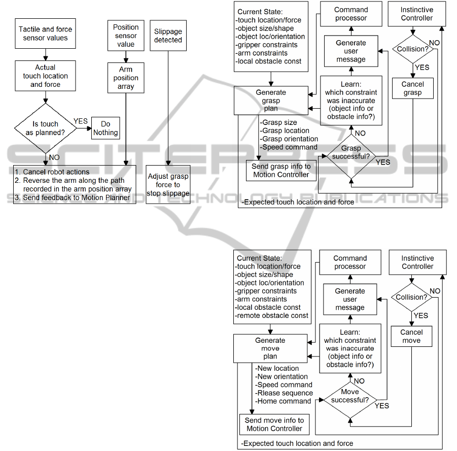
like reactions to unintended touch, collision and
slippage in order to prevent damage to robot
hardware and the manipulated object;
b. Provide collision and slippage feedback to the
Motion Planning module to help improve its
performance.
Figure 3: Instinctive Controller algorithm structure.
2.3 Motion Planner
The decision making module employed in the
previous version of the manipulation controller
framework (Dzitac and Mazid, 2012) has now been
incorporated into the motion planner in an attempt to
eliminate redundancy, reduce controller complexity,
and improve its robustness.
The Motion Planning module (Figure 4 and
Figure 5) has been designed to determine the actions
to be taken based on a novel target object selected
by user, of which the controller has no prior
knowledge. When user selects the target object and
the new desired object location, the planner
performs the following tasks:
a. Decides whether the target object can be
grasped based on object info and obstacle info
obtained from vision camera.
b. Decides whether the object can be moved to the
new location designated by user.
c. Decides gripper orientation for grasping and
releasing the object based on object
shape/size/location/orientation and the
surounding obstacles.
d. Generates a sequence of grasp and move actions
that have to be performed (move to object
location, orientate gripper, grasp object, move
object to new location, orientate object, release
object, go home).
e. Generates force and speed constraints for the
grasp and move actions based on object data.
f. Passes the generated information to the Motion
Controller module.
Figure 4: Object grasp planning algorithm structure
employed by Motion Planner.
Figure 5: Object move planning algorithm structure
employed by Motion Planner.
2.4 Motion Controller
The Motion Controller module (Figure 6) has been
designed to:
a. Generate a detailed sequence of motion path
points and orientations based on the action
sequence generated by the Motion Planning
RoboticGraspingandManipulationControllerFramework-ArchitectureRedevelopment
371
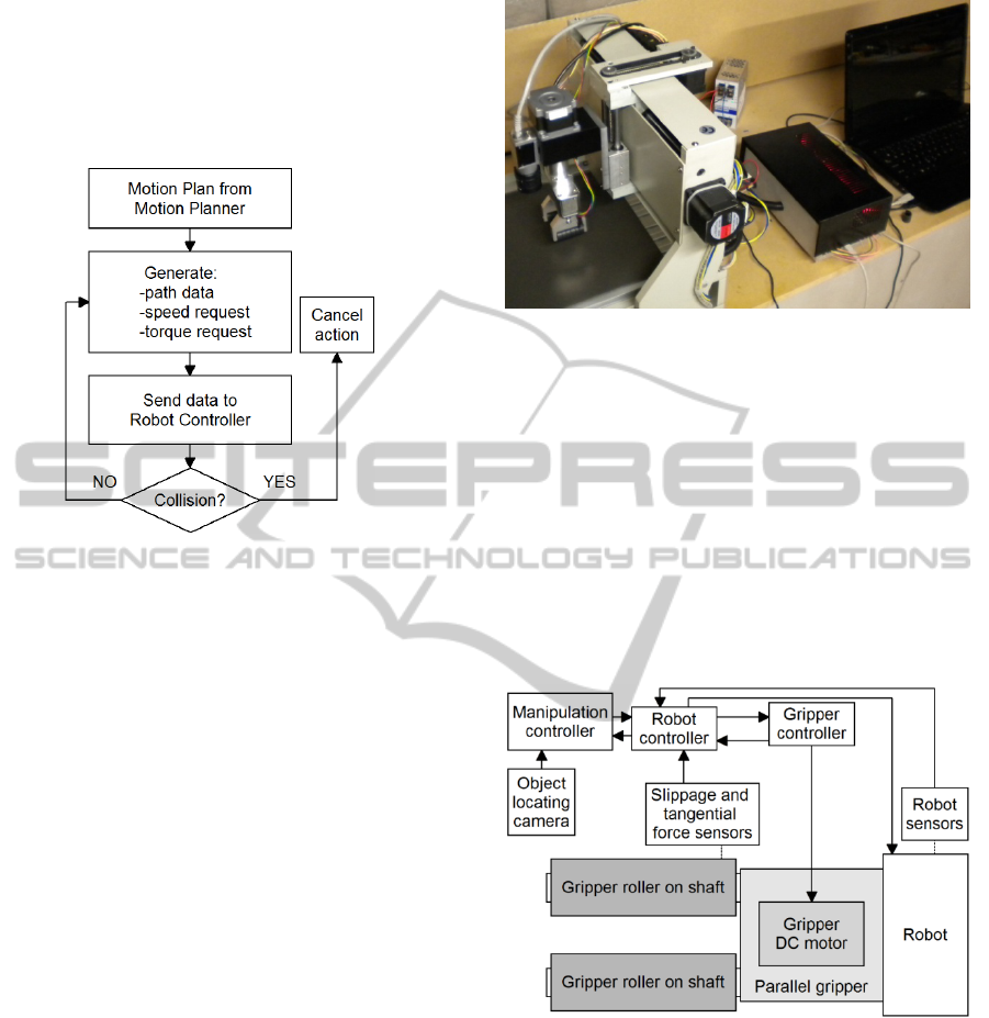
module.
b. Apply speed/acceleration and force constraints.
c. Feed the target position points, gripper
orientation and grasp actions at the appropriate
time to the robot controller that performs the
actual control of the robot.
Figure 6: Motion Control algorithm structure.
2.5 Robot Gripper and Arm Controller
The Robot consists of hardware and firmware that
responds to instructions received from the Motion
Controller and converts them to robot actions.
The robot is capable of accepting path data
(position coordinates and orientation), speed,
acceleration and torque commands, and executing
movement sequences according to this information.
Figure 7 depicts the experimental setup using a
basic XYZ+R robot equipped with an object
detection camera, friction-based slippage detection
gripper and a custom robot controller capable of
accepting and executing control commands from the
manipulation controller framework running on a PC.
The robot has four degrees of freedom and, apart
from being capable of movement in Cartesian
coordinates, it can rotate the gripper around its
vertical axis. This alows the robot to move to the
object position coordinates provided by the vision
function and rotate the gripper based on the object
orientation in the horizontal plane.
Although not very flexible, the robot can execute
object grasping and motion sequences that are
sufficient for carrying out any relevant object
grasping, manipulation and slippage detection
experiments.
The hardware for sensor signal digitising is
located in the robot controller. Currently the digital
filtering task is performed on the PC by the Sensing
Processor module. However, due to the need for real
Figure 7: Experimental setup for executing object grasping
and manipulation tasks.
time processing, it would be preferable to digitise
and filter the signals remotely before sending these
signals to the control PC.
Figure 8 describes schematically the
experimental setup of Figure 7. Note that the gripper
“jaws” (i.e. rollers on shafts) are also the slippage
and tangential force sensing elements. This gripper
allows reliable slippage and tangential force
measurement in one axis. The working principle of
this slippage sensing strategy is detailed in an earlier
paper (Dzitac and Mazid, 2012).
Figure 8: Schematic of the experimental setup for
executing object grasping and manipulation tasks.
3 EXPERIMENTATION
AND RESULTS
Object grasping and manipulation experimentation
has been conducted with the redeveloped
manipulation controller framework and slippage
sensing function to determine its ability to control
object slippage reliably.
ICINCO2014-11thInternationalConferenceonInformaticsinControl,AutomationandRobotics
372

The object manipulation has been conducted
using a custom parallel gripper capable of sensing
grasp force, and also tangential force and slippage in
the vertical direction. A rectangular aluminium
object of 100x50x22mm and weighing
approximately 300 grams has been grasped, lifted
vertically and moved to a new location at a
maximum acceleration of 100mm/sec and a
maximum speed of 300mm/sec.
The experiments conducted demonstrate that
using sensor fusion to monitor proximity to slippage
and using equations 1 and 3 to adjust grasp force
safety margin allows the controller to predict and
prevent object slippage more reliably.
A summary of the experimentation results is
presented in Table 1. All object manipulation
attempts were performed on the same object, using
the same acceleration, velocity and deceleration for
all manipulation attempts.
As a result of replacing the slow vision feedback
used in the previous version of the sensor fusion
function with tangential force feedback, the
improved slippage detection function gained
slippage detection speed and the ability to predict
proximity to slippage. In most circumstances the
vision feedback was either to slow or unconvincing.
The overall performance gain is evident from the
Table 1 results.
Table 1: Slippage prevention ability comparison of
previous and current slippage detection methods when
manipulating a novel object.
Number of
object lifting
attempts
Unpredicted
slippage using
previous method
Unpredicted
slippage using
current method
10 6 1
4 CONCLUSIONS
This paper presented the redevelopped manipulation
controller framework and the additional benefits that
the elimination of unnecessary control functions,
data processing and interaction redundancies bring
to safe and reliable object grasping and
manipulation. In particular the sensor fusion
function enhancements and the use of equations 1
and 3 to control grasp force safety margin resulted in
improved controller ability to predict, detect and
control object slippage in the robot gripper.
A practical method of estimating the static
coefficient of friction (using equation 2) during
object manipulation based on feedback from the
grasp force sensor and slippage sensor was
presented.
The manipulation controller framework
presented here could be used equally well with
Cartesian and articulated robots, because the motion
controller provides the target coordinates, force and
speed information, while the robot controller tells
the robot how to get there. This means that the
manipulation controller framework can work with
any robot controller that understands the motion,
force and speed commands received from the motion
controller module.
It is envisaged that this work will be useful to
researchers developing object manipulation
controller frameworks and slippage detection and
control strategies.
REFERENCES
Dzitac, P., Mazid, A. M., 2012. Modelling of a Grasping
and Manipulation Controller. In Proceedings
(Volume 2), ICINCO 2012 – 9th International
Conference on Informatics in Control, Automation and
Robotics, Rome, Italy, pp. 199 -204.
Howard, A. H., Bekey, G., 2000, Intelligent Learning for
Deformable Object Manipulation. In Journal of
Autonomous Robots, vol. 9, pp. 51-58.
Khalil, F. F., Payeur, P., 2007. Robotic Interaction with
Deformable Objects under Vision and Tactile
Guidance - a Review. In International Workshop on
Robotic and Sensors Environments, pp.1-6.
Prats, M., Sanz, P. J., del Pobil, P. A., 2009. Vision-
tactile-force integration and robot physical interaction.
In Conference on Robotics and Automation, 2009.
ICRA '09. IEEE International, pp. 3975-3980.
Wettels, N., Parnandi, A. R., Moon, J. H., Loeb, G. E.,
Sukhatme, G.S., 2009. Grip control using biomimetic
tactile sensing systems. In IEEE/ASME Transactions
on Mechatronics, vol. 14, pp. 718–723.
Smith, S., 1999, The Scientist and Engineer's Guide
to Digital Signal Processing 2nd Ed., California
Technical Publishing, San Diego, California.
Dzitac, P., Mazid, A. M., 2012, A method to control grip
force and slippage for robotic object grasping and
manipulation. In The Proceedings, 20
th
Mediterranean
Conference on Control and Automation, Barcelona,
Spain, pp. 116-121.
RoboticGraspingandManipulationControllerFramework-ArchitectureRedevelopment
373
