
Development of the Autonomous Mobile Overhead Traveling Crane
in Consideration of On-line Obstacle Recognition, Path Planning and
Oscillating Control
Y. Kawasaki, A. Kaneshige and S. Ueki
Toyota National College of Technology, Eisei-cho 2-1 Toyota-City, Aichi 471-8525, Japan
Keywords: Overhead Traveling Crane, Path Planning, Obstacle Recognition, Oscillating Control, Control Technology.
Abstract: In order to establish an autonomous overhead traveling crane system, it is needs to be constructed the
obstacle recognition system, the path planning system and the control system of suppression of object swing
automatically. These systems development is studied by our research group. In particular, the on-line
obstacle recognition system using an ultrasonic sensor and the on-line obstacle avoidance path planning
system of the on-line which extended the obstacle avoidance path planning method of the autonomous
mobile robot which Srinivas has proposed to the three-dimensional obstacle avoidance path planning system
are developed. Furthermore, the feed-forward control system using a notch filter is constructed. However,
the feed-forward control system was not able to control object swing which occurred during initial deviation
or transportation. Therefore, in order to improve the vibration suppression of object swing, 2-degrees of
freedom control system is constructed in this research. It is unified with the obstacle recognition system and
path planning system which are proposed until now, and the usefulness of the autonomous overhead
traveling crane system integrated was confirmed.
1 INTRODUCTION
Development of an automation or an autonomous an
overhead traveling crane are desired from viewpoint
of working efficiency or safety. In order to establish
an autonomous overhead traveling crane system, it is
needs to be constructed the obstacle recognition
system, the path planning system and the control
system of suppression of object swing automatically.
Especially, an obstacle recognition system and a
path planning system that can be quickly carried out
with an easy algorithm on-line are desired. These
systems development is proposed by our research
group (Kaneshige, 2012; Nagai,2011). In particular,
the on-line obstacle recognition system using an
ultrasonic sensor(USS) and the on-line obstacle
avoidance path planning system which extended the
obstacle avoidance path planning method of the
autonomous mobile robot which Srinivas (Srinivas,
1991) has proposed to the three-dimensional
obstacle avoidance path planning system are
developed (Kaneshige, 2012; Nagai, 2011). In these
proposed system, an obstacle avoidance path can be
derived by information of target position and any
obstacle position that is recognized by the obstacle
recognition system. This on-line path plan method
performs a path plan by the partial information of a
transportation environment recognized by USS of
the obstacle recognition system during transfer. The
path plan of the overhead traveling crane is
constructed to the goal position by repeating a
suggested process (algorithm). And the usefulness of
the proposed path planning method was evaluated
from a view point of a qualitative and a quantitative
(Nagai, 2011). On the other hand, the feed-forward
control system using a notch filter is constructed
(Kaneshige, 2012). However, the feed-forward
control system was not able to control object swing
which occurred during initial deviation or
transportation.
Therefore, in order to improve the vibration
suppression of object swing, two-degrees of freedom
control system is constructed in this research. It is
make to integrate in the obstacle recognition system
and path planning system which is proposed
previous researches, and the usefulness of the
autonomous overhead traveling crane system
integrated was confirmed.
382
Kawasaki Y., Kaneshige A. and Ueki S..
Development of the Autonomous Mobile Overhead Traveling Crane in Consideration of On-line Obstacle Recognition, Path Planning and Oscillating
Control.
DOI: 10.5220/0005047103820389
In Proceedings of the 11th International Conference on Informatics in Control, Automation and Robotics (ICINCO-2014), pages 382-389
ISBN: 978-989-758-040-6
Copyright
c
2014 SCITEPRESS (Science and Technology Publications, Lda.)
2 CONSTRUCTION OF
EXPERIMENTAL EQUIPMENT
AND OBSTACLE
RECOGNITION SYSTEM
General view of the overhead traveling crane
experimental equipment is shown in Fig.1. The
experimental equipment is operated by servomotor
attached in the X, Y, and Z-direction respectively. In
the X-direction, the girder of crane is moved, in the
Y-direction, the cart on the girder is moved, and in
the Z-direction, a object is gone up and down,
therefore, a object is transferred. The swing angle of
X-direction(
) and Y-direction(
) is measured by
the rotary encoder fixed to the cart as shown in Fig.
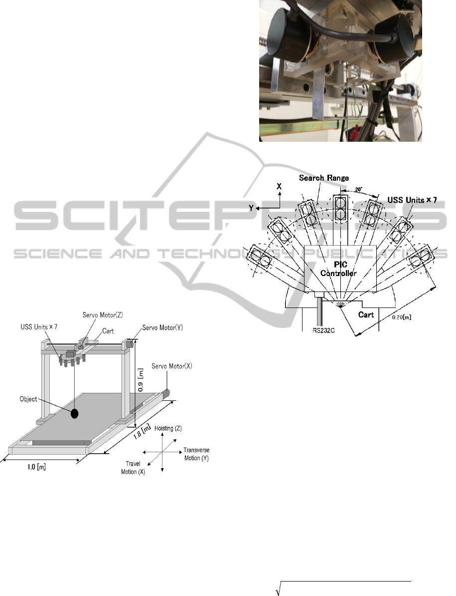
2. An ultrasonic sensor(USS) is used for obstacle
recognition in the obstacle recognition system. 7
units USS are set every 20 degrees in front of cart,
and it is recognized the height and the position of
obstacle in front of the circumference of
transportation object as shown in Fig.3, the obstacle
information is heights data for transportation space
segmented into0.05
m
. In this research, the upper
surface of the obstacle is assumed to be flat(as
parallelepiped).
Figure 1: Experimental equipment.
3 PATH PLANNING SYSTEM
The three-dimensional path planning system for an
overhead traveling crane proposed by our previous
research is described in this section(kaneshige,
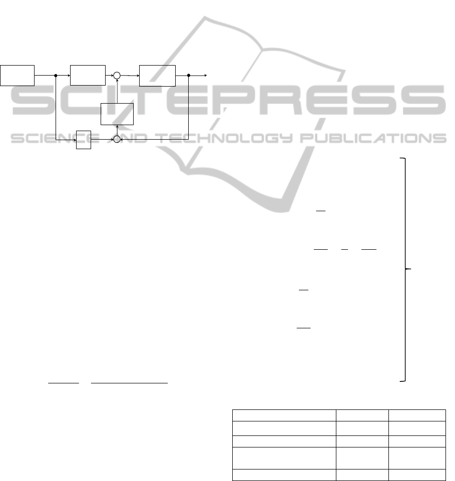
2012)(Nagai, 2011). Position relation of
transportation object(T) , obstacle(O) , goal(G) is
shown in Fig. 4.
fc
r
is a distance between
Figure 2: Measurement swing angle system.
Figure 3: Ultra sonic sensor.
transportation object and nearest obstacle to
transportation object, and then FC(Feasible Circle)
restricted transfer within a circle with the radius of
fc
r
is formed. In addition, NP(Next Position) is a
position to transfer transportation object by
calculation of once in FC. An equation derived NP
is determined by expanding obstacle avoidance
algorithm proposed by Srinivas to three-dimensional
as follows (Kaneshige, 2012; Nagai, 2011).
Objective function
22
)()(
onogn
DPDF
(1)
Subject to the constraint
222
2
)()()(
tntntnfc
zzyyxxr
(2)
Distance D
gn
between goal and NP is shown in (3).
222
)()()(
gngngngn
zzyyxxD
(3)
DevelopmentoftheAutonomousMobileOverheadTravelingCraneinConsiderationofOn-lineObstacleRecognition,
PathPlanningandOscillatingControl
383
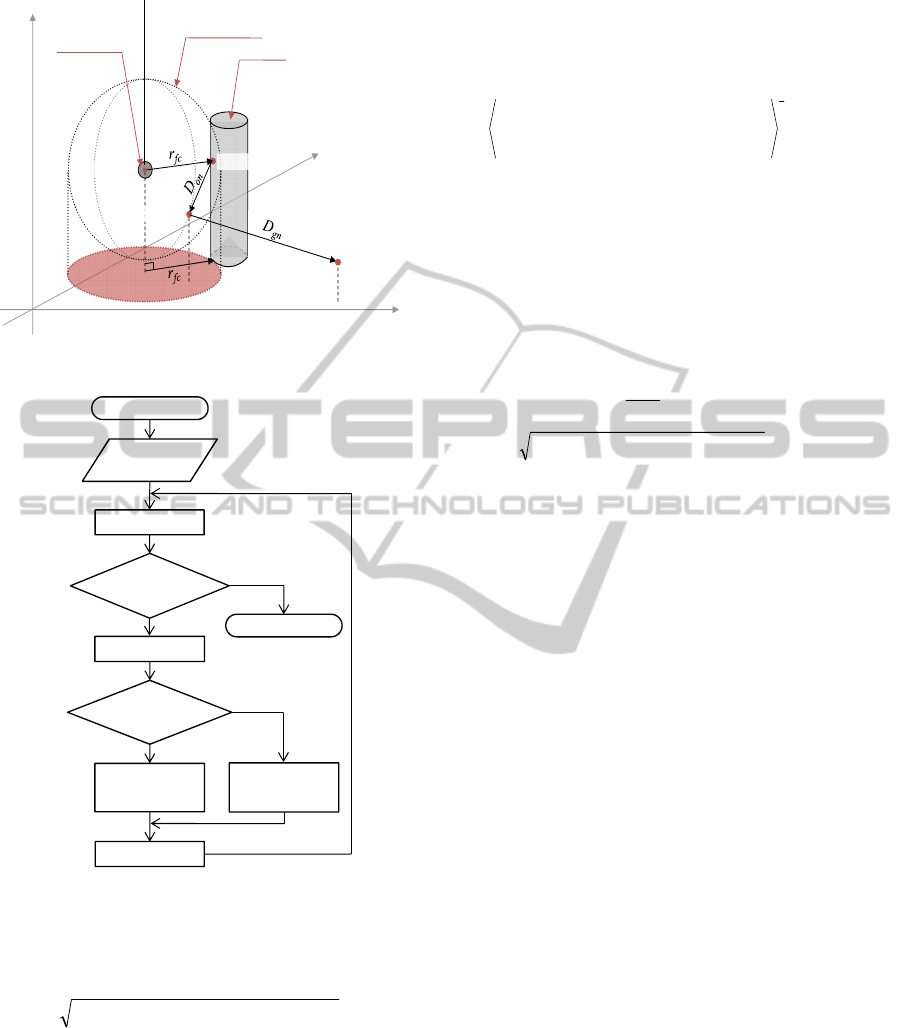
Figure 4: Position of each constituent in workspace.
Figure 5: System flowchart.
Distance D
on
between obstacle and NP is shown in
(4).
222
)()()(
onononon
zzyyxxD
(4)
(1) is minimized by Lagrange multiplier method. In
addition, NP is derived by calculating minimized
(1) and (2) at (
n
x
,
n
y
,
n
z
).
CxCxxPxxx
ttootgn
/)()(
(5)
CyCyyPyyy
ttootgn
/)()(
(6)
CzCzzPzzz
ttootgn
/)()(
(7)
where
)/(r
)z(zP)z(z
)y(yP)y(y)x(xP)x(x
C
fc
2
1
2
tgotg
2
tgotg
2
tootg
r
t
(8)
NP is determined from (5), (6) and (7), therefore
transportation object is transferred to NP. In addition,
NP is determined from (5), (6) and (7) again when
obstacle is recognized. This process is repeated until
transportation object arrive at goal position.
o
P
of
(1) is a value of weighting to adjust
gn
D
and
on
D
.
ot
o
o
D
C
P
(9)
222
)()()(
tototoot
zzyyxxD
(10)
ot
D
is a distance between obstacle and
transportation object.
o
C
of (9) is a optional
coefficient to change size of avoidance path. Value
of
o
C
is determined after evaluating
o
C
. Value of
o
C
is 300
by confirming in previous research
(Kaneshige, 2012; Nagai, 2011).
Transportation path is generated by obstacle
information, position information of goal position.
Processing procedure flowchart of transportation
path is shown in Fig. 5. Processing procedure is as
follows.
A) Input initial condition of goal position and
o
C
B) Get transportation object position.
C) Get obstacle information of circumference of
transportation object from USS.
D) If obstacle is non-existent in range of detection
of USS, NP is determined to transfer to
direction of goal position.
E) If obstacle exist in range of detection of USS,
NP is determined based on (5), (6) and (7).
F) Transportation object is transferred to NP.
Transportation is finished if transportation object
position correspond with goal position when
transportation object position is gotten again.
x
Goal
y
z
Feasible Circle
Obstacle
Transferring
object
G(x
g
, y
g
, z
g
)
O(x
o
, y
o
, z
o
)
T(x
t
, y
t
, z
t
)
NP(x
n
, y
n
, z
n
)
End
Start
DetermineNP
inalgorithm
NPisdirection
ofthegoal
Move
Goal?
Scanfield
Wasobstacle
detected?
Yes
No
Yes
No
Inputinitial
condition
Getposition
A
B
C
D
E
G
F
ICINCO2014-11thInternationalConferenceonInformaticsinControl,AutomationandRobotics
384
4 CONTROL SYSTEM OF
SUPPRESSION OF LOAD
SWING
The feed-forward control system using a notch filter
is constructed in previous research(Kaneshige,
2012). However, the feed-forward control system
was not able to control object swing which occurred
during initial deviation or transportation. Therefore,
in order to improve the vibration suppression of load
swing, 2-degrees of freedom control system by using
feed-forward control system and feed-back control
system is constructed. Block diagram of control
system is shown in Fig. 6.
Figure 6: Constitution of the control system.
4.1 Generate Reference and Notch
Filter
As for transportation control system, trapezoidal
input voltage reference for speed control inputted
each servo motor in X-direction and Y-direction is
generated based on NP calculated by path planning
system. In addition, transportation object is
transferred to NP because input voltage reference
applied notch filter is inputted to each servo motor.
Natural frequency ingredient of input voltage
reference is ridded by notch filter. Therefore, object
swing is suppressed. Function of notch filter is
shown in (11).
is damping ratio of object swing.
n
is natural frequency of object swing.
2
2
2
2
in
out
2
)s(V
)s(V
)s(G
nn
nn
ss
ss
(11)
4.2 Overhead Traveling Crane Model
In order to derive a feed-back gain used for feed-
back control, state space model of overhead
travelling crane is necessary. Therefore, the state
space model is derived as shown in (12) and validity
of the model is confirmed. Subscript d means a
direction.
t
x
,
t
y
is cart position of each direction.
n
x
,
n
y
is reference trajectory input of each
direction.
,
is object swing each angle.
x
T
,
y
T
is
motor time constant of each direction.
x
K
,
y
K
is
motor gain of each direction.
x
D
,
y
D
is object swing
friction of each angle. L is rope length. However,
rope length is constant because experimental
equipment is small. Therefore, rope length is
regarded linear time invariant. In addition, time
variant control system for changing rope length is
designed by previous research(Terashima, 1999).
Each parameter value is shown in Table 1. The
model is inspected by using MATLAB(Simulink).
Further, cart position and object swing of
experimental equipment is compared when input
voltage reference similar to simulation is inputted.
Comparison result of cart position is shown in Fig.
7(a). Comparison result of object swing is shown in
Fig. 7(b). As shown from Fig. 7, simulation and
experimental equipment described mostly the same
line both cart position and object swing. Therefore,
validity of derived model of overhead crane is
confirmed.
2
() () ()
() ()
01 0 0
1
000
00 0 1
1
0
0
1000
1
0100
00010
0001
,,,
,,,
ddddd
ddd
d
d
d
d
d
dd
d
d
T
xrtrt
yrtrt
xt A t B t
yt Cxt
T
A
gD
TL L
mL
T
BC
K
TL
xxxxx
xyyyy
T
(12)
Table 1: Parameter of overhead crane.
X Y
Motor Gain [m/s・V]
0.2242 0.1118
Motor Time Constant 0.01 0.01
Shake Friction
Coefficient[kg/s]
10
-7
10
-7
Rope length [m] 0.65 0.65
Notch Filter
Crane
System
Path
Planning
Control
Gain
+
reference[V]
-
+ -
u(t)d
1/S
x(t)d
DevelopmentoftheAutonomousMobileOverheadTravelingCraneinConsiderationofOn-lineObstacleRecognition,
PathPlanningandOscillatingControl
385
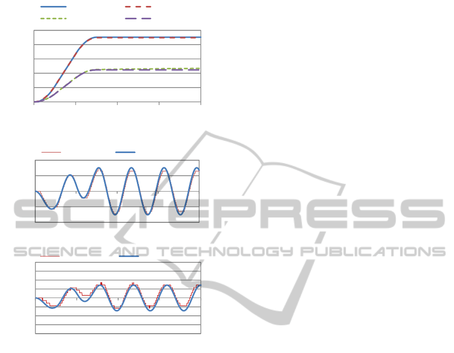
(a) Cart position
(b) Swing angle
Figure 7: Validation of crane model.
4.3 Construction of Feed-Back Control
System
A control system of each X-direction and Y-
direction is constructed independently. A control
system of Z-direction isn’t constructed because it is
guaranteed regardless of object swing. As for
constructed control system, notch filter is applied to
value of input voltage reference derived by path
planning system, and feed-back gain is applied to
deflection between reference position and
transportation object position(
tr
xx
,
tr
yy
),
deflection between reference speed and
transportation object speed(
tr
xx
,
tr
yy
), object
swing(
,
) and object swing speed(
,
).
Therefore, suppression of object swing is conducted
by comparing these values. Based on confirmed
overhead crane model, Feed-back gain is derived by
using optimal regulator. An optimum control input
due to state feed-back is determined by minimizing
evaluation function as shown in (13).
(13)
u
(14)
Feed-back gain is derived by deciding value of
Q
and
R
with trial and error.
4.4 Feed-back Gain
How to determine the feed-back gain an explained in
this section. In this research, feed-back gain are
determined by comparing the suppression of object
oscillating and the conformity to the reference
trajectory. Feed-back gain are determined by which
is setting the weight of R and Q as follows.
Case1: In case of considering the suppression of
objects oscillation
01.0000
020000
0001.00
00010
Q
, R = 1
x
F
= [3.1623 1.1746 13.9871 0.5470]
y
F
= [3.1623 0.7775 13.7073 0.9018]
Case2: In case of considering the conformity to the
reference trajectory
01.0000
02000
0001.00
000500
Q
, R = 1
x
F
= [22.3607 3.1368 3.9146 -1.5658]
y
F
= [22.3607 2.8927 4.4057 -0.2216]
Comparison between reference trajectory
generated by path planning system and
transportation path(experimental results) each feed-
back gain is shown in Fig. 8(a)(b). X-direction
object swing of each case are shown in Fig. 9(a)(b).
Y-direction object swing of each case are shown in
Fig. 10(a)(b). Comparison of transportation time is
shown in Table 2. As for transportation result,
comparison is made due to X-Y surface because
control system of Z-direction isn’t constructed.
As shown from Fig. 8(a)(b), it can be seen that
the transportation path of case 2, as compared with
case 1, is conformed to the reference trajectory. As
0
0,05
0,1
0,15
0,2
0,25
02468
X, Y[m]
time[sec]
X experimental X simulation
Y experimental Y simulation
-0,04
-0,02
0
0,02
0,04
02468
α[rad]
time[sec]
α experimental α simulation
-0,04
-0,03
-0,02
-0,01
0
0,01
0,02
0,03
0,04
02468
β[rad]
time[sec]
β experimental β simulation
ICINCO2014-11thInternationalConferenceonInformaticsinControl,AutomationandRobotics
386
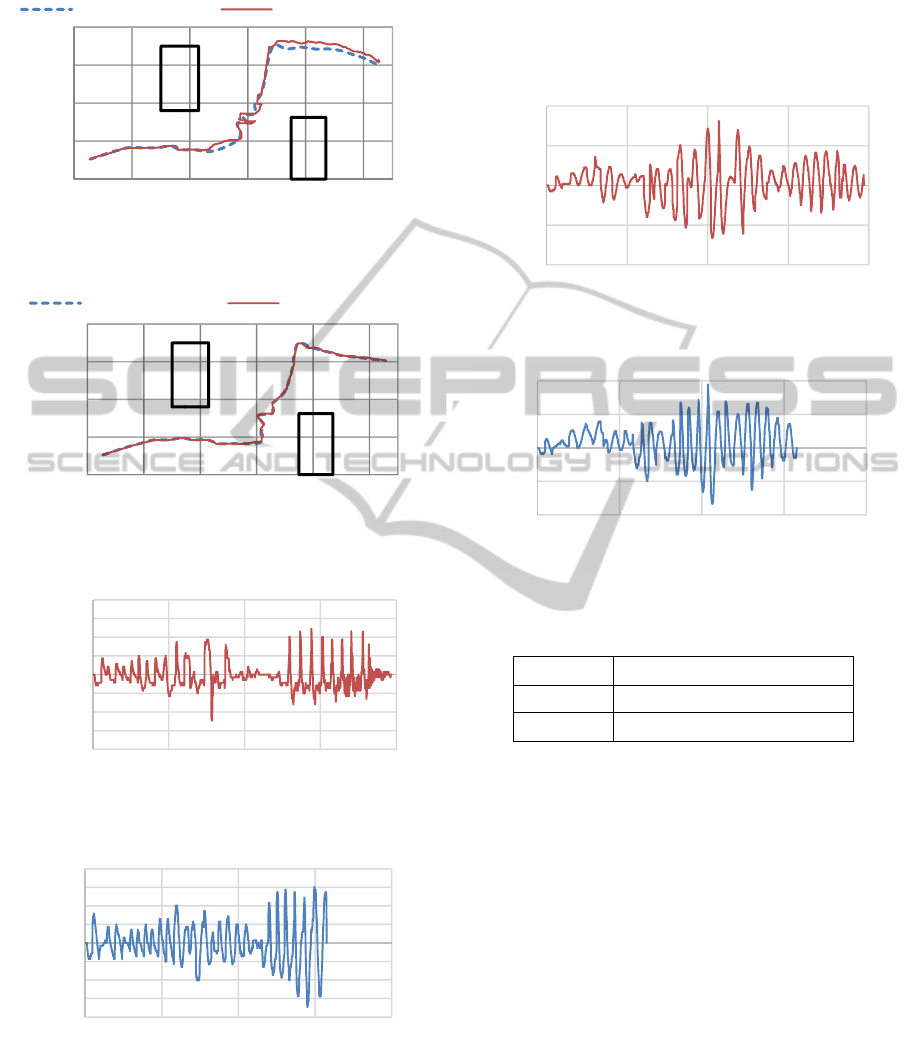
shown from Fig. 9(a)(b), it can be seen that case 1
suppresses object swing a little as compared with
Figure 8(a): experimental result of path (case 1).
Figure 8(b): experimental result of path (case 2).
Figure 9(a): X-direction object swing (case 1).
Figure 9(b): X-direction object swing (case 2).
case 2. However, both of them suppress object
swing to some extent. As shown from fig. 10(a)(b),
it can be seen same as Fig 9(a)(b). As shown from
Table 2, it can be seen that transportation time of
case 2 is shorter than case 1. From the above results,
it seems that case 2 is more effective than case 1
because the transportation path is conformed to the
reference trajectory, transportation time is shorter
and object swing is suppressed to some extent.
Figure 10(a): Y-direction object swing(Case 1).
Figure 10(b): Y-direction object swing(Case 2).
Table 2: Comparison of transportation time.
Transportation time
Case 1 39.38sec
Case 2 31.58sec
5 TRANSPORTATION
EXPERIMENT
Two-degrees of freedom control system by feed-
back gain derived in section 4.4 and notch filter are
implemented in control computer. In addition,
transportation experiment is conducted.
Experimental results of two-degrees of freedom
control system are compared against experimental
results of feed-forward control system, and then
usefulness of control system constructed is
confirmed.
5.1 Experiment Condition
Transferring space of X-direction is 1.2[m], Y-
direction is 0.75[m], and Z-direction is 0.35[m] by
0
200
400
600
800
0 200 400 600 800 1000
Y[mm]
x[mm]
Reference trajectory Transportation path
0
200
400
600
800
0 200 400 600 800 1000
Y[mm]
x[mm]
Reference trajectory Transportation path
-0,08
-0,06
-0,04
-0,02
0
0,02
0,04
0,06
0,08
0 10203040
α[rad]
time[sec]
-0,08
-0,06
-0,04
-0,02
0
0,02
0,04
0,06
0,08
0 10203040
α[rad]
time[sec]
-0,1
-0,05
0
0,05
0,1
010203040
β[rad]
time[sec]
-0,1
-0,05
0
0,05
0,1
0 10203040
β[rad]
time[sec]
DevelopmentoftheAutonomousMobileOverheadTravelingCraneinConsiderationofOn-lineObstacleRecognition,
PathPlanningandOscillatingControl
387
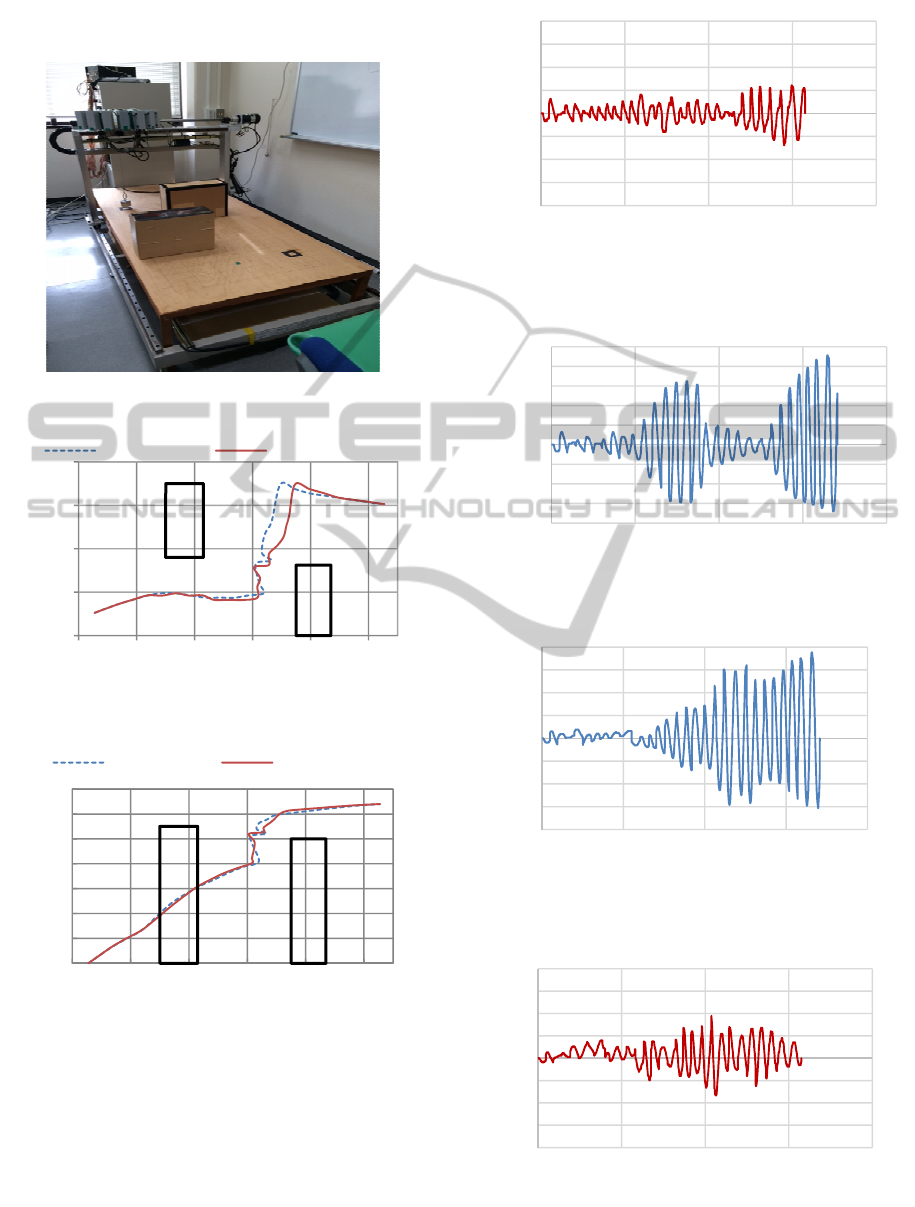
experimental equipment of overhead crane. Two
obstacles are disposed between start position S(50,
Figure 11: Placement of obstacles.
Figure 12(a): Experimental result of path(X-Y surface).
Figure 12(b): Experimental result of path(X-Z surface).
100, 0) and goal position G(1050, 650, 320) as
shown in Fig. 11. It is assumed that transportation
object avoid obstacles and transportation object
reach for goal position. Transportation object is used
a column of 1.0kg in weight, 50mm in radius, and
30mm in height. Placement of obstacles are shown
in Fig. 11
Figure 13(a): X-direction object swing(2 degrees of
freedom).
Figure 13(b): X-direction object swing(Feed-forward).
Figure 14(a): Y-direction object swing(2 degrees of
freedom).
Figure 14(b): Y-direction object swing (Feed-forward).
0
200
400
600
800
0 200 400 600 800 1000
Y[mm]
x[mm]
Feed-forward 2 degrees of freedom
0
50
100
150
200
250
300
350
0 200 400 600 800 1000
Z[mm]
X[mm]
Feed-forward 2 degrees of freedom
-0,2
-0,15
-0,1
-0,05
0
0,05
0,1
0,15
0,2
0 10203040
α[rad]
time[sec]
-0,2
-0,15
-0,1
-0,05
0
0,05
0,1
0,15
0,2
0,25
0 10203040
α[rad]
time[sec]
-0,2
-0,15
-0,1
-0,05
0
0,05
0,1
0,15
0,2
0 10203040
β[rad]
time[sec]
-0,2
-0,15
-0,1
-0,05
0
0,05
0,1
0,15
0,2
0 10203040
β[rad]
time[sec]
ICINCO2014-11thInternationalConferenceonInformaticsinControl,AutomationandRobotics
388

Table 3: Experimental value.
transportation time
Feed-forward 34.19sec
Two-degrees of freedom 31.51sec
5.2 Experimental Results
Comparison of transportation path(X-Z surface, X-Y
surface) is shown in Fig. 12(a)(b), X-direction object
swing of each case are shown in Fig. 13 (a)(b), Y-
direction object swing of each case are shown in Fig.
14(a)(b), and transportation time is shown in Table 3.
As shown from Fig. 12(a)(b), change of
transportation path is occurred a little because feed-
back control system is used. However, both of
transportation paths are almost the same, therefore it
can be said that suitable transportation is conducted
because transportation object is avoided obstacles
from start position to goal position. As shown from
Fig. 13(a)(b), Fig. 14(a)(b) and Table 3,
transportation time of two-degrees of freedom
control system is shorter than feed-forward control
system. In addition, object swing of two-degrees of
freedom control system is less than feed-forward
control system. Therefore, the usefulness of
constructed transportation control system is
confirmed through experiments.
6 CONCLUSIONS
The conclusion in this research for an autonomous
mobile crane system can be summarized as follows.
The on-line obstacle recognition system using
an USS and the on-line obstacle avoidance path
planning system is constructed.
Based on system integrated, the transportation
control system to suppress a object swing is
constructed by using two-degrees of freedom
control system
Feed-back gain considering the suppresion of
object oscillation and the conformity to the
reference trajectory are determined, and then it
is confirmed by experiment.
The usefulness of constructed transportation
control system is confirmed through
experiments.
REFERENCES
A. Kaneshige, et al.: 2012-9. Development of the
Autonomous Overhead Travelling Crane with Real
Time Path-Planning Based on Obstacle Information,
Proc. of 13th IFAC Symposium on Control in
Transportation Systems CTS'2012 Sofia (Bulgaria),
Sept.12-14, 2012, pp.274/279.
S. Nagai, A. Kaneshige and S. Ueki: 2011-8. Three-
Dimensional Obstacle Avoidance Online Path-
Planning Method for Autonomous Mobile Overhead
Crane, Proc. of the 2011 IEEE IEEE/ASME
International Conference on Mechatronics and
Automation, Beijing(China), CD-ROM, pp.1497/1502.
K. Terashima and A. Kaneshige: 1999. Load-Position
Control of Overhead travelling crane in terms of
Fixed-Pole App.roach for 3-D Trasfer Path, Proc.of
the European Control ECC'99, Karlsruhe, Geramany,
Aug-Sep. BP11.
Y. L. Srinivas and S. N. Kramer, 1991. An Algorithm For
Real-Time Obstacle Avoidance A Conference and Path
Planning For Mobile Robots, Advances in Design
Automation, 2, 507-514.
DevelopmentoftheAutonomousMobileOverheadTravelingCraneinConsiderationofOn-lineObstacleRecognition,
PathPlanningandOscillatingControl
389
