
Remote Handling Crane System for Use in Small Argon
Compartment Hot-cell
Jong Kwang Lee, Byung Suk Park, Seung-Nam Yu, Kiho Kim, Jonghui Han and Il-je Cho
Nuclear Fuel Cycle Process Technology Development Division, Korea Atomic Energy Research Institute, Daejeon, Korea
Keywords: Crane, Hot-cell, Argon Compartment, Remote Operation, Maintenance.
Abstract: In this paper, we describe the design of a novel crane system for use in a small argon hot-cell where only a
mechanical master-slave manipulator (MSM) within the limitation is available for the maintenance of the
crane. To get a practically achievable solution for the design problem, we devised a remote actuation
mechanism in which the electrical parts of the crane are separated from the mechanical parts and installed
inside the workspace of the MSM for remote maintenance. Even though the design concept does not provide
a thoroughly sufficient solution because the mechanical parts are placed out of the MSM’s workspace, the
durability of the mechanical parts can be easily increased if they have a high safety margin. Therefore, the
concept may be one of best solutions for our special crane system. In addition, we developed a servo-control
system based on absolute positioning technology; therefore, it is possible for us to perform the given tasks
more safely through an automatic operation.
1 INTRODUCTION
Crane systems are widely used to transport heavy
items and hazardous materials in factories,
construction spots, docks, and nuclear power plants.
Three factors such as speed, accuracy, and safety,
are the most important factors in crane operations in
which the swing of the payload degrades all of these
factors during transport operations. Therefore,
intensive research works have been focused on to
minimize the swing of the payload (Abderrahim,
Gimenez and Balaguer, 2008).
As for the maintenance of industrial crane
systems, it is possible to maintain or repair the failed
unit through direct access even through the work is
to be performed in a potentially dangerous high
place. In a special facility, such as a “hot-cell” in
which direct access by human operators is not
possible due to the high radioactivity, the crane
systems are considered indispensable. In this case,
the maximum speed should be limited for safe
operation, and remote maintainability is one of the
most important design requirements. There are two
approaches for the maintenance of the hot-cell crane
system. First, a damaged crane is towed by an
auxiliary crane installed in the upper floor
maintenance room through a hatch door (Piolain,
Geffard and Coudray, 2006). Second, the hot-cell
crane system is moved to an adjacent maintenance
area on the same floor, and then the operator
performs hands-on repair of the failed unit after
decontamination (Bradley, Burgess, Graves,
Spampinato and Varma, 2004). In these methods,
the the crane system should have redundant drives
for the preparation of a failure of a normal driving
line to move the crane to the maintenance area.
In this paper, we describe the design of a special
crane system for use in a small argon compartment
hot-cell where no auxiliary lifting system for the
rescue of the crane is available.
2 DESIGN REQUIREMNTS OF
CRANE SYSTEM
An Advanced spent fuel Conditioning Process
Facility (ACPF) was constructed at the KAERI site
as a demonstration facility of laboratory-scale
pyroprocessing technology (You et al., 2009). The
ACPF is an air environment hot-cell and it has two
separated areas: the process cell and maintenance
cell, the dimensions of which are 8.1m (L) x 2m (W)
x 4.3m (H) and 2.2m (L) x 2m (W) x 4.3m (H). The
wall of the hot-cell is made of thick heavy concrete
390
Lee J., Park B., Yu S., Kim K., Han J. and Cho I..
Remote Handling Crane System for Use in Small Argon Compartment Hot-cell.
DOI: 10.5220/0005047303900395
In Proceedings of the 11th International Conference on Informatics in Control, Automation and Robotics (ICINCO-2014), pages 390-395
ISBN: 978-989-758-040-6
Copyright
c
2014 SCITEPRESS (Science and Technology Publications, Lda.)
to maintain the dose rate at less than 0.01 mSv/h in
the operation area. Five pairs of lead-glass shielding
windows are installed on the operation side of the
hot-cell. Each window workstation is equipped with
a pair of MSMs. Several batch operations have been
completed using pure uranium and depleted uranium
(DU).
Even though existing process equipment was
equipped with a built-in argon supply system, it
suffered from some problems arising from corrosion
and moisture because it was installed in an air
environment cell. Therefore, the necessity of an
argon hot-cell was a pressing issue for enhancing the
performance of the processing equipment. As a part
of the refurbishment project, a redesign of the ACPF
began in March 2012 (Park, Lee, Yu, Kim and Cho,
2013). An argon hot-cell will be constructed inside
the existing process cell as a compartment, as shown
in Fig. 1, and its volume is approximately 11% of
the ACPF, with dimensions of 1.8m (L) x 2m (W) x
2.65m (H). The existing lead-glass shielding
window and two sets of MSMs will be used without
any modification of the argon compartment. On the
other hand, a small crane system with a load
capacity of 1.50 kN will be installed on the argon
compartment. However, since the crane system will
be installed on the ceiling of the argon compartment,
the design constraints arising from facility
dimensions, a lack of a remote handling device, and
process operation conditions should be considered
from the design stage.
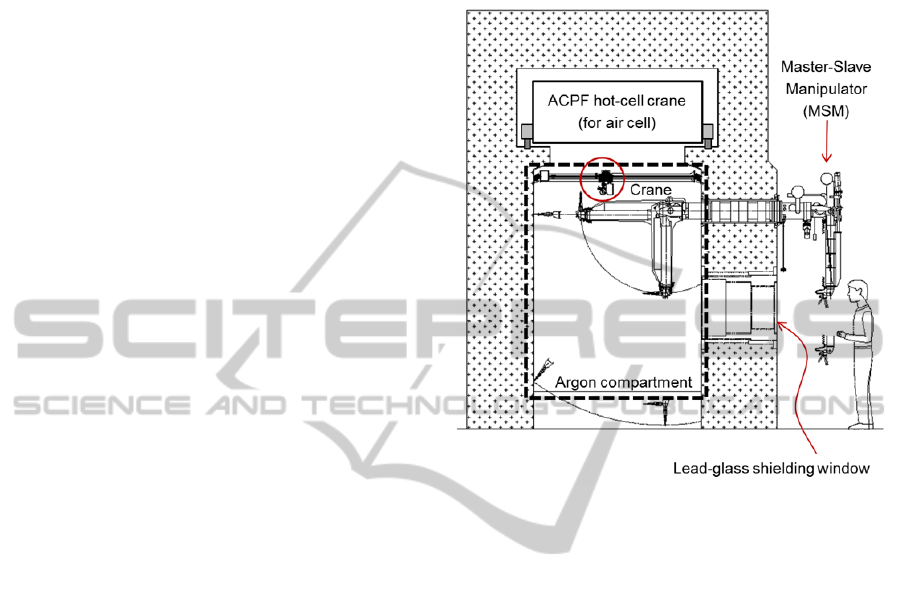
As shown in Fig. 1, the MSM cannot reach the
argon compartment crane, which indicates that there
is no maintenance means for the crane. We
established several design requirements. The first
design constraint arising from the space-limited cell
is that the maximum height of the crane should not
exceed 300 mm. This constraint means a minimum
height of the crane whose load hook can be placed
over the MSM without contact.
The second design requirement is related to the
operation condition of the process equipment. Since
the manual operation while viewing the equipment
through a shielding window may lead to
mishandling due to inaccurate distance feeling, it is
desirable for the crane to operate with accurate
movements like a robot. Therefore, a non-slip
structure is more advantageous. In addition, direct
access by a human operator to a hot-cell is
restrictively allowed after decontamination, or is not
absolutely allowed; therefore, all mechanical parts
that are installed on the ceiling should be designed
with strength and durability. In addition, because the
MSM is the only available remote handling system
in the argon compartment, motors, sensors, and limit
switches should be placed inside the workspace of
the MSM, and they should be designed to provide
easy attachment/detachment.
Figure 1: Cross section view of the conceptual design of
the argon compartment. The dashed box indicates the
argon cell that will be constructed inside the existing
ACPF as a compartment.
3 DESIGN OF REMOTE
HANDLING CRANE SYSTEM
3.1 Remote Actuation Mechanism
There is no way to design a crane system that
throughly fulfills the design requirements owing to
the space-constrained environment as well as the
reach limitation of the MSM. To find the best
solution for this crane design problem, we made two
assumptions:
Electrical parts (motor, sensor) have more
possibilities of a breakdown than the
mechanical parts.
The durability of the mechanical parts can be
easily increased if they have a high safety
margin.
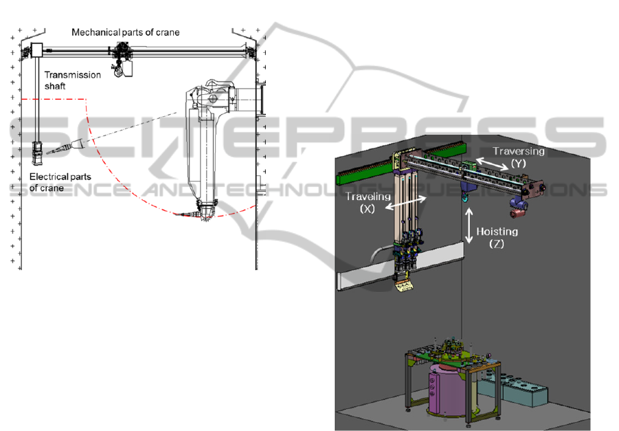
Based on these two assumptions, we devised a
remote actuation mechanism using the transmission
shaft. As shown in Fig. 2, the mechanical parts and
electical parts of the crane system are separated and
connected through a transmission shaft. That is,
RemoteHandlingCraneSystemforUseinSmallArgonCompartmentHot-cell
391
electrical parts consisting of a servomotor, a position
sensor, and two limit switches, located inside the
workspace of the MSM, transmit the power to the
mechanical parts. Even though the design concept
does not provide a thoroughly sufficient solution
because the mechanical parts are placed out of the
MSM’s workspace, it may be one of best solutions
for our special crane because two design
assumptions are practically reasonable. However,
this concept brings a negative effect on the
transmission efficiency.
Figure 2: Concept of remote actuation mechanism for
power transmission.
This mechanism resembles that of a tendon driven
manipulator in which the torque generated by the
motor installed on the base is transmitted through
the tendon to the load links placed far from the base.
This approach is advantageous in reducing the bulk
and weight of the arm, and therefore similar effects
may be expected in the crane system. For example,
the space of the excluded electrical parts from the
crane make it possible to reduce the height of the
crane system with a slight sacrifice in width. In
addition, because the power and signal cables can be
placed in a lower position near the servo-motor, the
volume of the cable carrier is not required in a
higher position near the mechanical parts of the
crane, which maximizes the working volume of the
traveling motion of the crane.
3.2 Design of Mechanical Structure
Figure 3 shows the 3D CAD model of the prototype
crane system with a remote actuation mechanism.
As in an industrial bridge crane, it consists of three
motion modules: a traveling system, traversing
system, and hoist system. To provide accurate
motion and absolute positioning, all three axes of the
crane system have been designed to be equipped
with an anti-slip driving structure. As for the
traveling system, the overall weights of the crane
and loads are supported by four wheels axially
coupled with pinion gears. The gears mate with a
rack gear mounted on the runway rail to prevent the
system from slippage. The level of the wheels can be
adjusted using a shim plate.
The traversing system moves a trolley hoist in
the forward/backward direction from the viewpoint
of the operator, and supporting frame and girder
have been designed in consideration of the stress and
deflection at the maximum payload condition.
Because the traversing system is operated using a
linear motion system such as an LM guide and ball
screw unit, and its motion features anti-slip property
with a small amount of friction.
Figure 3: 3D CAD model of crane system.
The detailed design of the hoist is shown in Fig. 4. It
consists of a worm gear, a chain wheel, and a ball
spline. Two spline nuts were inserted in both sides
of the worm. Since the spline mechanism is used to
provide nearly frictionless linear motion while
allowing the member to transmit torque
simultaneously, the traversing motion of a ball screw
cannot interfere with the hoist motion. As a good
way to increase the durability of the mechanical
parts of the crane, we used commercially proven
components such as a ball-screw, ball-spline, and
linear motion guide so as not to be broken within the
expected lifetime of the crane system.
ICINCO2014-11thInternationalConferenceonInformaticsinControl,AutomationandRobotics
392
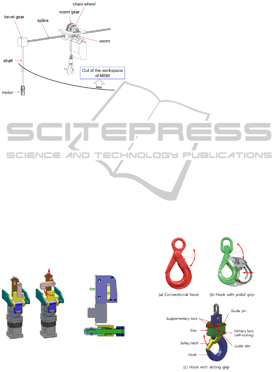
Figure 4: Novel hoisting concept employing remote
actuation mechanism in which the driving power is
transmitted from a remotely installed servo-motor.
3.3 Modular Design for Easy
Maintenance
A remote handling module is a module that can be
remotely operated (connected or disconnected) by a
robot or manipulator and its design must include
interfaces that are more easily handled with
manipulators and special tools. Therefore, the easy
maintenance concept is a major goal in the design of
remote handling modules because it minimizes the
shut-down times. The driving module should be
firmly fixed to the frame while connecting the
transmission shaft to the motor shaft, and it can also
be easily separable from the frame in a remote
manner. To do so, we applied a cam-slider
mechanism as a locking device. In a sensor module
consisting of a wire sensor and two limit switches,
the ball-spring mechanism is used to ease the
mechanical attachment/detachment (Fig. 5).
Figure 5: Easy maintenance concept of remote handling
modules: a drive module (left) and a sensor module (right).
3.4 Hook
During crane operations, hooking is one of the most
easy and simple operations if a human operator
performs it. On the other hand, if it is performed by
the master-slave operation using a robotic gripper, it
is very difficult and complicated work to perform
because it consists of three motions: safety latch
release, gripping, and hooking. Furthermore, the
work performed using one gripper may be much
harder since the handling points of three motions are
different from each other. As an improvement of the
conventional hook shown in Fig 6 (a), a pistol grip is
added to the hook and its gripping motion is
interlocked with the opening of the latch. However,
the eccentricity between the centre of the hook and
the centre of the grip often causes an unstable grip.
Furthermore, the initial approaching posture of the
gripper to the pistol grip should be set appropriately
at the beginning of the operation, which is
occasionally difficult without a change in the
location of the manipulator.
A novel hook, as shown in Fig. 6 (c), has been
devised to provide a more efficient means for easy
remote handling. A circular grip is concentrically
coupled at the central line of the hook so that a
gripper can approach the grip from any initial
direction, and it can also grasp the hook firmly. As
the gripper lifts the grip of the hook up, the safety
latch rotates to be opened with the interaction of the
guide slots and guide pins fixed on the safety latch.
Therefore, the gripper should be required to perform
two simple motions such as a grip and up/down
movement at the same handling point, which
dramatically simplifies the remote handling of the
hook.
Figure 6: Conventional hook and its improvements.
RemoteHandlingCraneSystemforUseinSmallArgonCompartmentHot-cell
393
4 CONTROL SYSTEM
OF CRANE
Manual operation of a crane while watching inside
the hot-cell through a lead-glass shielding window
often fails in accomplishing the given tasks due to an
imprecise operator cognition. In addition, because
the location of the processing equipment is known to
be a priori in an argon compartment, predefined
sequential operations can simplify the complicated
operation. Therefore, we designed a remote control
system based on absolute positioning and automatic
operation to provide a safer and more efficient
operation of the processing equipment. The crane
has 3 degrees of freedom actuated with Tamagawa
brushless servo motors equipped with a resolver
sensor. We designed a control system on the basis of
the servo control. The absolute position of each
motion axis can be measured using a wire sensor in
which a multi-turn potentiometer is coupled with a
steel wire.
To increase the performance of the absolute
positioning measurement, we used a combination of
a wire sensor and resolver pulse reading. When the
control system is re-initialized, it reads the absolute
position from the wire sensor through an analog-to-
digital conversion, and set the value as the initial
position of the crane system. Next, the motion
control system uses resolver pulse readings instead
of wire sensor readings because the resolver pulse is
much more robust against noise. Since the analog
readings from a wire sensor are normally affected by
noise, the average value of the preset time duration
is chosen as the initial value. In addition, whenever
the limit switch is activated, the control system
resets the origin as the preset value in absolute
Cartesian coordinates. This makes it possible for the
control system to be operated in absolute positioning
mode.
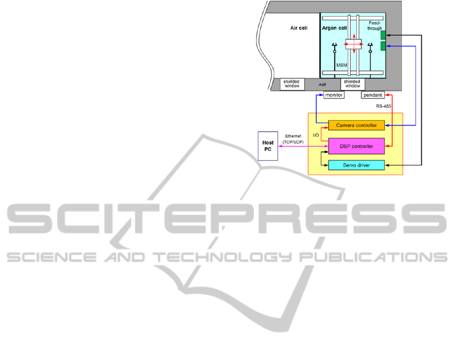
Figure 7 shows the overall layout of the control
system in which a digital signal processor (DSP)-
based controller interfaces with both the camera
controller and motion controller. Servo motors are
operated in position control mode with various speed
profiles. The DSP controller receives control
parameters from the PC through network
communication, and transfers operational
information to the PC. The operator can manipulate
the crane system by looking through the lead-glass
shielding window and viewing a supplementary
camera monitor. All functions concerning the
control of the crane and camera are interfaced with a
touch pendant through RS-485 communication.
Figure 7: Overall layout of the integrated control system.
5 PROTOTYPE OF CRANE
SYSTEM
Figure 8 shows a full-scale evaluation mock-up
facility that provides same operation conditions and
useful means for testing and verifying the remote
operability and maintainability of the constructed
process equipment, cell utilities, and relevant
devices in advance before they are installed in the
argon compartment of the ACPF. Cell utilities
consisting of a window, a cell light, an antechamber
for transportation, a door, two sets of MSMs, a feed-
through, and a camera system were installed inside
the argon compartment, while a camera monitor and
touch pendant for crane control were installed
around the window in the operation area. Several
mechanical and electrical tests were performed to
check whether the crane system is performing to the
desired level of performance. The maximum
deflection of the girder frame is about 0.3 mm,
which may not influence the performance of the
linear motion system, such as the ball screw and ball
spline. Because the mechanical parts of the crane
system were placed over the MSM, the load hook
can be moved along the ceiling without any
interference with the MSMs. Several control modes
such as jog mode, absolute positioning mode, and
sequential operation mode can be selectively
performed using a touch pendant in which several
graphic pages linked to each control mode.
As shown in Fig. 9, several remote maintenance
operations have been performed to verify that the
driving modules and sensor modules can be replaced
using an MSM only. From the experimental results,
all the design goals have been generally achieved,
ICINCO2014-11thInternationalConferenceonInformaticsinControl,AutomationandRobotics
394
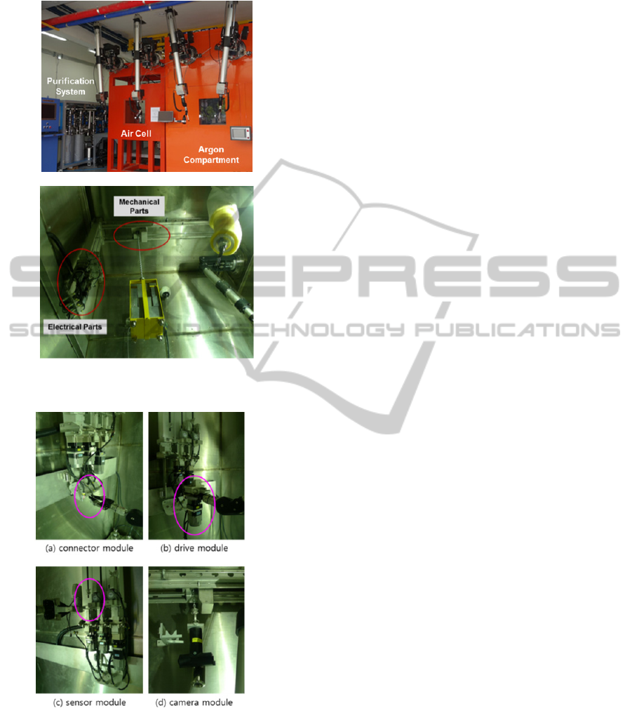
especially in the concept of remote maintainability.
Figure 8: Operation area (top) and inside of argon
compartment (bottom) of the constructed mock-up facility.
Figure 9: Evaluation test of remote maintenance.
6 CONCLUSIONS
In this work, we developed a crane system for use in
a small argon compartment which has several
constraints on the facility, remote handling device,
and process operation. To increase the remote
maintainability of the crane system, we devised a
novel crane system in which its mechanical part and
electrical parts are separated and connected through
a transmission shaft. In this concept, the electrical
parts, which have more possibilities of a breakdown
than mechanical ones, can be remotely replaceable
while the mechanical parts are designed to have a
high safety margin so as not to be broken within the
expected lifetime of the crane system. In addition,
all hardware and software of the DSP motion control
system based on absolute positioning technology
were developed and implemented for the control of
the crane system; therefore, it is possible for us to
perform the given tasks more safely through
automatic operation. From several operation and
maintenance tests of the constructed prototype crane
system, all design goals have been generally
achieved, especially in the concept of remote
maintainability. We are now applying an anti-sway
control technique to provide a more accurate and
safer operation of the process equipment.
ACKNOWLEDGEMENTS
This work was supported by Nuclear Research &
Development Program of National Research
Foundation of Korea (NRF).
REFERENCES
Abderrahim, M., Gimenez, A., Diez, R., Balaguer, C.
(2008). Anti-swing input shaping control of an
automatic construction crane. IEEE Transaction on
Automation Science and Engineering. 5(3). 549-xxx.
Bradley, E. C., Burgess, J. B., Graves, V. B., Spampinato,
P. T., Varma, V. K. (2004). Archimedes filter plant
remote maintenance system design,” 10th Int. Conf. on
Robotics and Remote Systems for Hazardous
Environments.
Park, B. S., Lee, J. K., Yu, S. N., Kim, K., Cho, I. J.
(2013). Design of ACPF Argon compartment and
purification system. Proceedings of the Korean
Radioactive Waste Society Conference. 167-168.
Piolain, G., Geffard, F., Coudray, A. (2006). Using an
industrial robot for maintenance telerobotic operations
in active cells at Cogema recycling plant,” European
Nuclear Conference.
You, G.-S., Choung, W.-M., Ku, J.-H., Cho, I.-J., Kook, D.
H., Kwon, K.-C., Lee, E.-P., Lee, W.-K. (2009).
Design and construction of an advanced spent fuel
conditioning process facility (ACPF). Nuclear
Engineering and Technology. 41(6). 859-866.
RemoteHandlingCraneSystemforUseinSmallArgonCompartmentHot-cell
395
