Seam Tracking Control of Welding Robotic Manipulators Based on
Adaptive Chattering-free Sliding-mode Control Technology
Youmin Hu
1
, Jie Liu
1
, Bo Wu
1
and Ming-Feng Ge
2
1
School of Mech. Sci. and Eng., Huazhong University of Science and Technology, Luoyu Rd 1037, Wuhan, China
2
College of Automation, Huazhong University of Science and Technology, Luoyu Rd 1037, Wuhan, China
Keywords:
Seam Tracking Control, Chattering-free, Adaptive Sliding-mode Control (ASMC), Welding Robotic Manipu-
lator, Large-scale Structure Component.
Abstract:
A novel adaptive sliding mode control (ASMC) algorithm is derived to deal with seam tracking control prob-
lem of welding robotic manipulator, during the process of large-scale structure component welding. The
controllers robustness is verified by the Lyapunov stability theory, and the analytical results show that the pro-
posed algorithm enables better high-precision tracking performance with chattering-free than classic sliding
mode control (SMC) algorithm.
1 INTRODUCTION
Large-scale structure component holds a large pro-
portion in the large engineering machinery, with a
very high importance. As main bearing component,
its connection mode is mainly composed of welding
parts. Therefore, the welding quality directly affects
the performance of the large-scale structure compo-
nent, to some extent, determines the overall quality of
the engineering machinery product itself, and the cost
of the production.
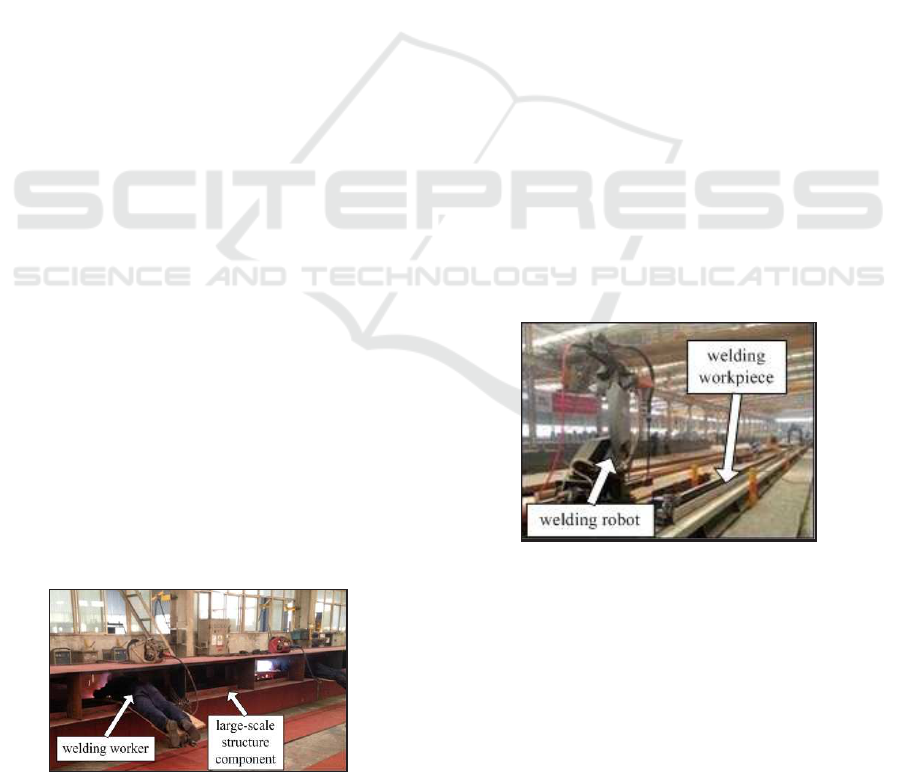
Figure 1: Manual welding is still dominated and adopted
(Provided by Weihua Group in Henan, China).
Unfortunately, manual welding is still dominated
and adopted in the manufacturing of the large-scale
structure component, as shown in Figure 1 above.
Currently, welding robotic automation improves the
welding quality, increases productivity and sets men
free from unhealthy, monotonous and poor working
conditions in industrial areas, as illustrated in Figure
2.
Figure 2: Welding robot in crane welding production line
(Provided by Nucleon (Xinxiang) Crane Co., Ltd in Henan,
China).
However, due to its main characteristic is big size
and large tonnage, it leads to difficulties in the pro-
cess of robotic welding. For example, the beam of
large crane is about 100 meters long. And the large-
scale structure component has diverse forms of weld
seams, such as flat, vertical and horizontal, which
would form welding residual deformation, such as
flexural deformation, distortion, waves of panel, etc.
In general, the robotic welding process of large-scale
structure component in the large engineering machin-
ery is more difficult, and needs higher technical re-
quirements than in the general structure component.
In order to overcome or restrain various uncertain
influences, caused by the large-scale structure compo-
nents weld seam, on welding quality, it is promising
to develop and improve intelligent technologies for
welding robots (Chen and Lv, 2014). Among these
417
Hu Y., Liu J., Wu B. and Ge M..
Seam Tracking Control of Welding Robotic Manipulators Based on Adaptive Chattering-free Sliding-mode Control Technology.
DOI: 10.5220/0005055104170420
In Proceedings of the 11th International Conference on Informatics in Control, Automation and Robotics (ICINCO-2014), pages 417-420
ISBN: 978-989-758-040-6
Copyright
c
2014 SCITEPRESS (Science and Technology Publications, Lda.)

intelligent technologies, tracking control of robotic
manipulators has a great of attention. Tracking con-
trol is needed to make each joint track a desired tra-
jectory as close as possible. Many control algorithm
such as computer torque method (Craig, 1989), opti-
mal control (Ruderman, 2014), adaptive control (Slo-
tine and Li, 1987), variable structure control (VSC)
(Cao and Ren, 2012), neural networks (NNs) (Yan
and Wang, 2012) and fuzzy system (Cruz and Mor-
ris, 2006) have been proposed to deal with this robotic
control problem. However, robotic manipulators are
highly nonlinear, highly time-varying and highly cou-
pled. Moreover, there always exists uncertainty in the
system model such as external disturbance, parame-
ter uncertainty, sensor errors and so on, which cause
unstable performance of the robotic system (Guo and
Woo, 2003).
In this paper, a novel adaptive sliding mode con-
trol (ASMC) algorithm is derived to deal with seam
tracking control problem of welding robotic manipu-
lator, during the process of large-scale structure com-
ponent welding. Its well known that classic sliding
mode control (SMC) will cause chattering, which is
a crucial disadvantage to the stability of the system,
making the controller designing become extremely
troublesome. The controllers robustness is verified by
the Lyapunov stability theory, and the analytical re-
sults show that the proposed algorithm enables better
high-precision tracking performance with chattering-
free than classic SMC.
The layout of the paper is as follows. Section 2
presents the dynamic model of welding robotic ma-
nipulator, and some relevant properties are discussed.
In Section 3, a novel adaptive sliding mode controller
is developed and analyzed for the tracking control of
welding robotic manipulators. Simulation examples
are given to demonstrate the performance of the pro-
posed controller in Section 4. Finally, we offer brief
conclusions and suggestion for further research.
2 DYNAMIC MODEL OF
WELDING ROBOTIC
MANIPULATORS
In general, the dynamic model of the 3-link welding
robotic manipulator is given as follows
M(q) ¨q+C(q, ˙q) ˙q+ g(q) + d(t) = u, (1)
where M(q) = M
T
(q) ∈ R
3×3
is the symmetric pos-
itive definite inertia matrix; q ∈ R
3
denotes the joint
position vector; C(q, ˙q) ∈ R
3×3
is the Coriolis and
centrifugal torques; g(q) ∈ R
3
is the vector of gravita-
tional torques; d(t) ∈ R
3
denotes the bounded distur-
bance; and u ∈ R
3
represents the torque input vector.
Several fundamental properties of the robot model
(1) can be obtained as follows.
Property 1. The matrix
˙
M(q) − 2C(q, ˙q) is skew sym-
metric matrix, i.e.,
x
T
˙
M(q) − 2C(q, ˙q)
x = 0, ∀x ∈ R
3
.
Property 2. For arbitrary x, y ∈ R
3
, we get that
M(q)x+C(q, ˙q)y+ G(q) = Y(q, ˙q, x, y)θ,
where Y(q, ˙q, x, y) denotes the regression matrix, θ is
the constant unknown parameter vector.
Property 3. The unknown disturbance d(t) is as-
sumed to be unknown, but bounded, i.e., kd(t)k < η.
3 CONTROLLER DESIGN
3.1 Adaptive Sliding Mode Controller
The objective of designed controller is to drive the
joint position q to the desired trajectory position q
d
.
First we define the tracking error as following:
˜q = q − q
d
. (2)
Let the sliding surface
s =
˙
˜q+ β ˜q, (3)
where β = diag[β
1
, β
2
, β
3
] in which β
i
is a positive
constant.
The objective of controller can be achieved by
choosing the control input u, so that the sliding sur-
face satisfies the sufficient condition (Slotine and Li,
1989; Slotine and Li, 1991). Let the reference state
˙q
r
= ˙q− s = ˙q
d
− β ˜q, (4)
and
¨q
r
= ¨q− ˙s = ¨q
d
− β
˙
˜q. (5)
Then the control law u is designed as
u =
ˆ
M(q) ¨q
r
+
ˆ
C(q, ˙q) ˙q
r
+ ˆg(q) − K
r
sgn(s)
α
, (6)
where
ˆ
M(q),
ˆ
C(q, ˙q) and ˆg(q) are the estima-
tions of M(q), C(q, ˙q) and g(q) respectively; K
r
=
diag[K
r11
, K
r22
, K
r33
] is a diagonal positive definite
matrix; sgn(s)
α
is defined as
sgn(x)
α
=
|x
1
|
α
sign(x
1
), |x
2
|
α
sign(x
2
), |x
3
|
α
sign(x
3
)
T
,
(7)
and x ∈ R
3
, 0 < α < 1.
ICINCO2014-11thInternationalConferenceonInformaticsinControl,AutomationandRobotics
418
Then combining system (1) with the control law
(6), we can conclude
[
ˆ
M(q) −
˜
M(q)](˙s+ ¨q
r
) + [
ˆ
C(q, ˙q)−
˜
C(q, ˙q)](s+ ˙q
r
)+
ˆg(q) − ˜g(q) + d(t) =
ˆ
M(q) ¨q
r
+
ˆ
C(q, ˙q) ˙q
r
+ ˆg(q)−
K
r
sgn(s)
α
,
(8)
where
˜
M(q) =
ˆ
M(q) − M(q),
˜
C(q) =
ˆ
C(q) −C(q) and
˜g(q) = ˆg(q) − g(q). Thus system (8) becomes
M(q) ˙s+C(q, ˙q)s+ d(t) =
˜
M(q) ¨q
r
+
˜
C(q, ˙q) ˙q
r
+
˜g(q) − K
r
sgn(s)
α
.
(9)
By using property 2, since the matrixes M(q),
C(q, ˙q) and g(q) are linear in terms of the manipulator
parameters, system (9) can be written as
˜
M(q) ¨q
r
+
˜
C(q, ˙q) ˙q
r
+
˜
G(q) = Y(q, ˙q, ˙q
r
, ¨q
r
)
ˆ
θ, (10)
and therefore
M(q) ˙s+C(q, ˙q)s+d(t) = Y(q, ˙q, ˙q
r
, ¨q
r
)
˜
θ−K
r
sgn(s)
α
.
(11)
Based on the properties above, the adaptation law
is designed as following:
˙
ˆ
θ = −ΓY
T
s. (12)
3.2 Stability Analysis
Considering the following Lyapunov function candi-
date for system (11)
V =
1
2
s
T
M(q)s+
1
2
˜
θ
T
Γ
−1
˜
θ, (13)
where θ is a 3-dimensional vector containing the un-
known manipulator and load parameters,
ˆ
θ is its esti-
mate, and
˜
θ =
ˆ
θ− θ denotes the parameter estimation
error vector. According to the property 1, Equation
(11) and (12), the derivative of the chosen Lyapunov
function can be derived as:
˙
V = −s
T
d(t) − s
T
K
r
sgn(s)
α
.
By using property 3, we can conclude
˙
V ≤ kskkd(t)k − λ
min
(K
r
)ksk
α+1
≤ kskη− λ
min
(K
r
)ksk
α+1
= −ksk(λ
min
(K
r
)ksk
α
− η).
(14)
Then we have the following theorem.
Theorem 1. For system (1) under controller (6) and
(12), if λ
min
(K
r
) > 0, 1 > α > 0 and Γ > 0, the system
trajectory will converge to the neighborhood of s = 0
as
ksk ≤
η
λ
min
(K
r
)
1
α
(15)
in finite time.
Proof. Notice that when (15) holds, from (14), we
can conclude
˙
V ≤ 0. Then by the finite time stabil-
ity theory, the neighborhood (15) can be reached in
finite time. This completes the proof.
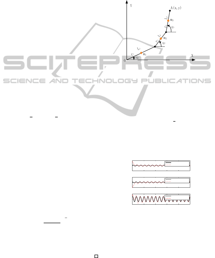
4 SIMULATION
Simulation is performed by using a 3-link non-linear
planer robot manipulator, as shown in Figure 3, which
dynamic model is derived by methods in (Spong and
Vidyasagar, 2008).
Figure 3: A 3-link robot manipulator.
The robotmanipulatorsparameter values are m
1
=
0.5kg, m
2
= 1.5kg, m
3
= 1.3kg, l
1
= 1m, l
2
= 1m,
l
3
= 1m, r
1
= 0.5m, r
2
= 0.5m, and r
3
= 0.5m. The
moment of inertia are i
1
= 2kg· m
2
, i
2
= 2kg· m
2
, and
i
3
= 2kg · m
2
. The initial conditions of the robot ma-
nipulator are given as q
1
(0) = 8, q
2
(0) = −9, q
3
(0) =
1.5, ˙q
1
(0) = 8, ˙q
2
(0) = −9, and ˙q
3
(0) = 1.5. The
reference signals are given by q
d1
= sin(3πt), q
d2
=
cos(3πt), and q
d3
= sin(3πt +
1
3
π). The bounded
disturbance is selected as d
1
(t) = 5sin(t), d
2
(t) =
2.5cos(t), d
3
(t) = 5sin(2t).
Besides, the parameter α in Equation (6) is set as
α = 0.6, and the gain K
r
in Equation (6) is designed
as K
r
= diag[300, 300, 300].
0 2 4 6 8 10
−10
0
10
time(s)
Angle response
Ideal position signal 1
Position tracking 1
0 2 4 6 8 10
−10
0
10
time(s)
Angle response
Ideal position signal 2
Position tracking 2
0 2 4 6 8 10
−2
0
2
time(s)
Angle response
Ideal position signal 3
Position tracking 3
Figure 4: Ideal position signal and position tracking output.
The simulation results above show that the de-
signed chattering-free ASMC can enable the abil-
ity of tracking control of the 3-link nonlinear planer
robot manipulator under various disturbances. Fur-
thermore, the proposed control algorithm doesnt re-
quire the precise dynamic model of the robot manip-
ulator.
SeamTrackingControlofWeldingRoboticManipulatorsBasedonAdaptiveChattering-freeSliding-modeControl
Technology
419
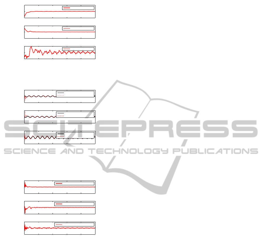
0 2 4 6 8 10
−10
0
10
time(s)
Angle response
Position tracking error 1
0 2 4 6 8 10
−20
0
20
time(s)
Angle response
Position tracking error 2
0 2 4 6 8 10
−1
0
1
time(s)
Angle response
Position tracking error 3
Figure 5: Position tracking output error.
0 2 4 6 8 10
−100
0
100
time(s)
Angle velocity response
Ideal position velocity signal 1
Position velocity tracking 1
0 2 4 6 8 10
−100
0
100
time(s)
Angle velocity response
Ideal position velocity signal 2
Position velocity tracking 2
0 2 4 6 8 10
−50
0
50
time(s)
Angle velocity response
Ideal position velocity signal 3
Position velocity tracking 3
Figure 6: Ideal position velocity signal and position velocity
tracking output.
0 2 4 6 8 10
−100
0
100
time(s)
Angle velocity response
Position velocity tracking error 1
0 2 4 6 8 10
−100
0
100
time(s)
Angle velocity response
Position velocity tracking error 2
0 2 4 6 8 10
−50
0
50
time(s)
Angle velocity response
Position velocity tracking error 3
Figure 7: Position velocity tracking output error.
5 CONCLUSIONS
We have proposed a novel chattering-freeASMC con-
troller for the seam tracking control of robotic manip-
ulator. And the proposed algorithm is more practical
than the traditional SMC controller. Besides, the sim-
ulation results have shown that the ability of the track-
ing control under various disturbances. In the end, a
challenging work for further research is to perform
the proposed algorithm in the seam tracking control
during the process of practical welding, and verify its
effectiveness.
ACKNOWLEDGEMENTS
The work here is supported by the National Natural
Science Foundation of China (No. 51175208), the
State Key Basic Research Program of China (NO.
2011CB706803), the Fundamental Research Funds
for the Central Universities (No. 2013ZZGH001).
REFERENCES
Cao, Y. C. and Ren, W. (2012). Distributed coordinated
tracking with reduced interaction via a variable struc-
ture approach. IEEE Transaction on Automatic Con-
trol, 57(1):33–48.
Chen, S. B. and Lv, N. (2014). Research evolution on
intelligentized technologies for arc welding process.
Jounal of Manufacturing Processes, 16:109–122.
Craig, J. J. (1989). Introduction to Robotics. Addison-
Wisley, 2nd edition.
Cruz, E. A. M. and Morris, A. S. (2006). Fuzzy-ga-based
trajectory planner for robot manipulators sharing a
common workspace. IEEE Transaction on Robotics,
22:613–624.
Guo, Y. Z. and Woo, P. Y. (2003). Adaptive fuzzy sliding
mode control for robotic manipulators. In 42nd IEEE
Conference on Control, Maul, Hawaii, USA.
Ruderman, M. (2014). Tracking control of motor drives us-
ing feedforward friction observer. IEEE Transactions
on Industrial Electronics, 61(7):3727–3735.
Slotine, J. E. and Li, W. (1987). On the adaptive control
of robot manipulators. The international journal of
robotics research, 6(3):49–59.
Slotine, J. E. and Li, W. (1989). Composite adaptive control
of robot manipulators. Automatica, 25:509–519.
Slotine, J. E. and Li, W. (1991). Applied Nonlinear Control.
The publishing company, Prentice Hall.
Spong, M. W. and Vidyasagar, M. (2008). Robot dynamics
and control. John Wiley & Sons.
Yan, Z. and Wang, J. (2012). Model predictive control for
tracking of underactuated vessels based on recurrent
neural networks. IEEE Journal of Oceanic Engineer-
ing, 37(4):717–726.
ICINCO2014-11thInternationalConferenceonInformaticsinControl,AutomationandRobotics
420
