
A Multi-layer Approach for Interactive Path Planning Control
Simon Cailhol, Philippe Fillatreau, Jean-Yves Fourquet and Yingshen Zhao
Laboratoire G
´
enie de Production, INP-ENIT, 47 Av d’Azereix, 65000 Tarbes, France
Keywords:
Interactive Path Planning, Control Sharing, Virtual Reality, Manipulation Tasks.
Abstract:
This work considers path-planning processes for manipulation tasks such as assembly, maintenance or disas-
sembly in a Virtual Reality (VR) context. The approach consists in providing a collaborative system associat-
ing a user immersed in VR and an automatic path planning process. It is based on semantic, topological and
geometric representations of the environment and the planning process is split in two phases: coarse and fine
planning. The automatic planner suggests a path to the user and guides him trough a haptic device. The user
can escape from the proposed solution if he wants to explore a possible better way. In this case, the interactive
system detects the user’s intention in real-time and computes a new path starting from the user’s guess. Exper-
iments illustrate the different aspects of the approach: multi-representation of the environment, path planning
process, user’s intent prediction and control sharing.
1 INTRODUCTION
The industrial product development process is going
faster and faster with more and more complex prod-
ucts. This leads to a need of tools allowing to rapidly
test a product at all the Product Lifecycle Manage-
ment (PLM) stages during the design phase. There is
a particular need for the tasks that involve human op-
erator manipulation. Here comes the interest of Vir-
tual Reality (VR) to run these tests with virtual pro-
totypes instead of expensive and time consuming real
ones (Fillatreau et al., 2013).
The main issue of tasks such as the ones involved
in assembly, dismantling and maintenance is to find
paths for the systems components and parts.
In this context, we propose a collaborative path-
finding system based on the interaction of a user im-
mersed in a VR simulation and an automatic path
planning process inspired from robotics.
Collaboration is defined as follows. The system
provides a initial planned path and the user is guided
along a computed trajectory through an haptic device.
However, the user can disagree with the proposed path
and try to go in another direction. The system must
compute a new path every time the user tries to test
another solution. Thus, it must be able to take into
account the user’s interactions in real-time to update
the suggested path and it requires control sharing be-
tween the user and the planner while performing the
task.
Robotics path planners mainly deal with geomet-
ric aspects of the environment. The VR context of our
planner involves a human in the loop with a different
environment representation. Thus, we chose to split
the planning process in two phases: a coarse plan-
ning dealing with topological and semantic models of
the environment (the places, their semantics and their
connectivity) and a fine planning dealing with geom-
etry and semantics (geometry of obstacles and places
and their complexity). This planning process par-
titioning provides a framework compatible with the
human path planning process described in (Ahmadi-
Pajouh et al., 2007).
Thus, the originality of the proposed interactive
path planner consists in using the information of
a multi-layer environment representation (semantic,
topological and geometric) for path planning, but also
for control sharing. All these environment models are
used by distinct planner layers to perform the coarse
(semantic and topological aspects) and fine (seman-
tic and geometric aspects) planning and to assist VR
user. The actions of the VR user are also taken into
account in real-time to update the proposed path.
This paper first gives, in section 2, an overview
of the state of the art of the different fields involved
(automatic path planning, sharing control, interactive
path planning). The architecture of our novel multi-
layer environment model and multi-layer interactive
planner is presented in section 3. The implementation
of this architecture on our VR platform is described
90
Cailhol S., Fillatreau P., Fourquet J. and Zhao Y..
A Multi-layer Approach for Interactive Path Planning Control.
DOI: 10.5220/0005055200900101
In Proceedings of the 11th International Conference on Informatics in Control, Automation and Robotics (ICINCO-2014), pages 90-101
ISBN: 978-989-758-040-6
Copyright
c
2014 SCITEPRESS (Science and Technology Publications, Lda.)
in section 4. Proof of concepts experiments are pre-
sented in section 5. These experiments show that
our novel multi-layer architecture finds more relevant
paths with faster processing times than the purely geo-
metrical approaches from the state of the art. Thus our
original approach allows a better real-time interactive
planning. Finally, section 6 summarizes the contribu-
tion of this paper and introduces the future steps of
this work to handle real industrial manipulation tasks.
2 STATE OF THE ART
2.1 Automatic Path Planning
The automatic path planning issue has been deeply
studied in robotics. These works are strongly based
on the Configuration Space (CS) model proposed by
(Lozano-Perez, 1980). This model aims at describ-
ing the environment from a robot’s Degrees of Free-
dom (DoF) point of view. The robot is described us-
ing a vector where each dimension represents one of
his DoF. A value of this vector is called a configu-
ration. So, all the possible values of this vector form
the CS. This CS can be split into free space and collid-
ing space (where the robot collides with obstacles of
the environment). With this model, the path planning
from a start point to a goal point consists in finding a
trajectory in the free space between these two points
in the CS.
The main strategies for path planning are given in
Table 1 where we distinguish the deterministic from
the probabilistic ones, but also, the ones involving
global approach from the ones involving local one.
More details on path planning algorithms and tech-
niques are available in (LaValle, 2006).
2.2 Control Sharing
There are already existing applications involving
path planning with human interactions (robot tele-
operation, semi-autonomous vehicles, virtual envi-
ronment exploration,...). These applications allow us
to identify two aspects in control sharing:
• Authority sharing: it aims at defining how the au-
thority on the system is shared between automatic
planner and human. To deal with this issue, differ-
ent strategies can be found in the literature. The
use of virtual fixtures (Marayong et al., 2003), the
allocation of the authority to the automatic sys-
tem for fine motion operations (Abbink and Mul-
der, 2010), the progressive transfer of authority
to robot while reaching the goal (Weber et al.,
2009), for an anthropomorphic robot, the control
of Cartesian position and orientation of end ef-
fector by user and joint control by planner (You
and Hauser, 2012). The authority sharing through
haptic devices were studied for semi-autonomous
vehicles driving. In this case, inspired from the
horse riding experience, (Flemisch et al., 2012)
suggests to use an haptic interface with a H-mode
to perceive user’s involvement and allocate the au-
thority according to it (the higher the user involve-
ment is, the more authority he has).
• Intent prediction: it aims at predicting the intent
of the human to define the goal of an automatic
controller and thus to assist the human perform-
ing the task. These techniques are strongly based
on behavior or trajectory recognition (Aarno et al.,
2005; Fagg et al., 2004; Li and Okamura, 2003;
Yu et al., 2005), on minimum jerk criterion (We-
ber et al., 2009), on model predictive control
(Loizou and Kumar, 2007; Anderson et al., 2010).
Dragan also recently proposed to find the targeted
goal among a set of potential ones from the cur-
rent movement direction (Dragan and Srinivasa,
2013).
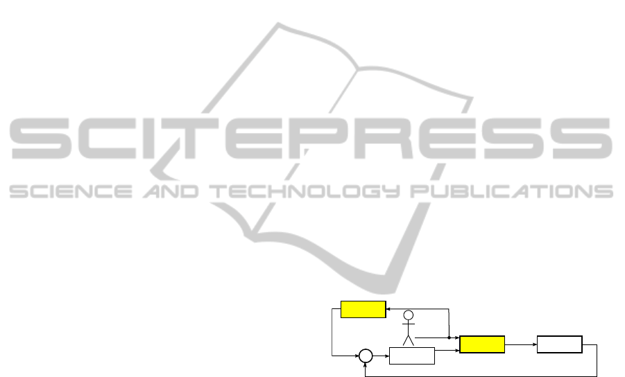
We summarize these two control sharing aspects
in Fig. 1 where the yellow boxes illustrate the control
sharing.
Figure 1: Sharing control model in semi-automated plan-
ning.
These techniques allow involving human and au-
tomatic planning system to perform a task. However,
the user’s actions do not affect the automatic planner
strategy to compute the path.
2.3 Interactive Path Planning
Some works propose collaboration between a human
operator and an automatic planner in the path plan-
ning process. The simpler one (Ladeveze et al., 2010)
uses a potential field strategy. An attractive field to
the goal is computed and used to guide the user thanks
to a haptic device. Another interactive planner from
(Ladeveze et al., 2010) guides the user along a com-
puted trajectory. To compute this trajectory in real-
time, a cell decomposition of the free space is used to
define a 3D tunnel. Then a RDT algorithm computes
a path within this 3D tunnel. The whole trajectory
AMulti-layerApproachforInteractivePathPlanningControl
91
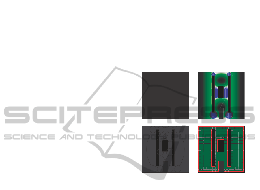
Table 1: The main path planning approaches.
Global approaches Local approaches
Deterministic
strategies
Cells decomposition
Roadmap
Potential fields
Probabilistic
strategies
PRM RRT and RDT
computation process is restarted if user goes away
from the proposed trajectory. Finally, an interactive
planner built from a probabilistic strategy (Ta
¨
ıx et al.,
2012), uses the users action to constraint the random
sampling of the configuration space in the RRT grow-
ing.
These three planners do not involve the human
user in the same way. The first one gives a strong
responsibility to the user (it’s up to him to deal with
the obstacles and to avoid collisions). The second one
suggests a whole trajectory the user can go away from
to restart the whole planning process. The last one
allows the user to point a direction that gives to the
planner a preferred direction to explore.
3 PROPOSED INTERACTIVE
PLANNER
This section presents the concepts of the strategy used
in the interactive planner shown in Fig. 2 where col-
ors are linked to the environment and planning layers:
yellow for geometry, orange for topology and red for
semantics. The same colors are used in the algorithms
to specify the involved layer. The concepts used are
illustrated here with 2D illustrations for clarity, but
the model stands identical for 3D simulations.
We argue that involving semantic and topological
aspects in path planning in addition to the common
geometric ones allows adapting the planning strat-
egy to the local complexity of the environment. To
deal with it, a coarse planning is performed first using
mainly semantic and topological information. Then,
heavy geometric path planning strategies are used
merely locally, (according to the place complexity).
This allows us to plan path without disturbing user’s
immersion in the VR simulation, and to take into ac-
count user’s action while performing the task to inter-
actively update the planned path.
The contribution of the work presented here is
thus two-fold:
• Guidance is provided in real-time to the user
by improving the path planning processing times
thanks to the semantic and topological informa-
tion of the environment.
• User’s actions are integrated in real-time in the
planning process and used to update the planned
path, and so, the guidance submitted to the user.
3.1 Environment Representation
O
1
O
2
O
3
O
4
P
1
P
2
P
5
P
7
P
8
P
6
P
9
P
10
P
3
P
4
a.2D environment. b.Environment’s places.
B
1,5
B
2,7
B
1,6
B
2,8
B
3,5
B
3,7
B
4,6
B
4,8
B
3,9
B
3,10
B
4,9
B
4,10
P
1
P
2
P
3
P
4
P
5
P
7
P
8
P
6
P
9
P
10
P
3
P
3
P
3
P
3
P
4
P
4
P
4
P
4
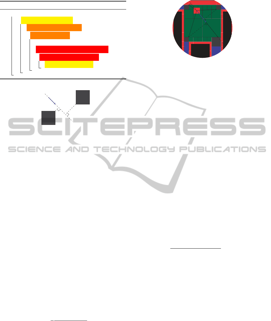
c.Topological graph. d.Free space decomposition.
Figure 3: Different perceptions of environment for user and
planner.
The topological information of the environment is
represented as a set of Places (P
1
to P
7
in Fig. 3.a)
and transition areas between those places, which we
call Borders; B
i, j
denotes the transition area between
places P
i
and P
j
. The topological layer of our environ-
ment model is made of a Topological graph (Fig. 3.c)
connecting places and borders. In this Topological
graph, the nodes correspond to the Borders, and the
edges to the Places. Fig. 4.a shows the distance be-
tween the borders’ centers in place P
4
. These dis-
tances are attributes set to the edges of topological
graph (Fig. 4.b for place P
4
).
The semantic information is attached to places.
Semantic attributes are assigned to the places to de-
scribe their complexity (size, shape, cluttering,...) for
path planning.
The geometric environment representation con-
sists in a geometric description of the environment’s
objects and a cell decomposition of the Free space.
The Objects are described with meshes; the free space
decomposition is made thanks to a quadtree (an octree
in 3D) (Fig. 3.d).
This muli-layer environment model is built as
given in algorithm 1. First (line 2), the 3D mesh
ICINCO2014-11thInternationalConferenceonInformaticsinControl,AutomationandRobotics
92
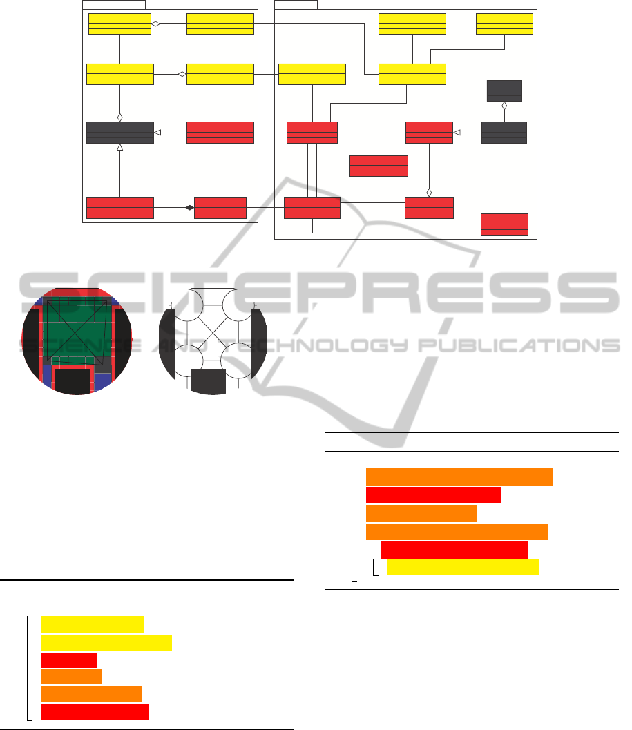
Environment representation
InteractivePlanner
1..* 1..*
1
2
1
1..*
1..*
0..*
1
1..*
Asks
◮ Asks
Determines◮
! Asks
Monitors◮
! Transmit probabilities
Environment obstacles Obstacle
Geometric cell
Intersects
Free space
Area Place
Border Topological graph
Semantic planner
Topological planner
Semantic interpreter
Topological path
Topological step
Geometric planner Local planner
Activates◮
Covers
Authority controller
◮ Uses
Torsor
! Produces
Trajectory
Step trajectory
Intent predictor
◮ Checks
Explores
Deals with
Figure 2: UML Domain model of environment representation and interactive planner.
× ×
×
×
d
1
d
2
d
3
d
4
d
5
d
6
B
4,6
B
4,8
B
4,9
B
4,10
d
1
P
8
P
6
P
P
d
2
d
3
d
4
d
6
d
5
a.Place P
4
distances. b.Place P
4
topological graph.
Figure 4: Topological graph building for place P
4
.
of environment Objects are loaded. Second (line 3),
the Free space decomposition is computed. Third
(line 4), the free space decomposition is used to iden-
tify the place. Fourth (line 5), the Places found are
used to define the Borders. Then (line 6), the Borders
are connected building the Topological graph. Last
(line 7), semantic attributes are set to the Places.
Algorithm 1: Build Environment Model.
1 begin
2 load Objects 3D Meshes ;
3 build Free space decomposition ;
4 build Places ;
5 build Borders ;
6 build Topological graph ;
7 assign attributes to Places ;
3.2 Planning Aspects
According to these environment models, the planning
process is split in two stages: the coarse planning in-
volving semantic and topological layers and the fine
planning involving semantic and geometric layers.
3.2.1 Coarse Planning
To adapt the geometric planning strategy to local
complexity, the whole path is split in steps. A step
refers to a place of environment representation. A step
also refers to a border to reach to fulfill the step. The
geometric planning strategy is thus chosen according
to the semantic information of step’s place.
Algorithm 2: Coarse Planning.
1 begin
2 update Topological graph (start & goal) nodes ;
3 update Topological graph’s costs ;
4 explore Topological graph ;
5 build Topological path and Topological steps ;
6 for Topological step ∈ Topological path do
7 define milestone for Topological step ;
Algorithm 2 describes this stage. Two nodes cor-
responding to start (S) and goal (G) configurations
are added to the topological graph (line 2). To direct
the graph exploration the Semantic planner, thanks to
the Semantic interpreter, assigns costs (C) to graph’s
nodes (n
i, j
) and edges (e
k
) (line 3). These costs are
chosen accordingly to the semantic information of in-
volved places (see (1)).
C
n
i, j
= f (sem(P
i
), sem(P
j
))
C
e
k
= f (d
k
, sem(P(e
k
)))
(1)
Where sem(P) is the semantic information of
place P, e
k
is a graph’s edge, d
k
its distance attribute
and P(e
k
) its place attribute; n
i, j
is the node linked to
the border B
i, j
between P
i
and P
j
.
AMulti-layerApproachforInteractivePathPlanningControl
93
S G
B
1,5
B
2,7
B
1,6
B
2,8
B
3,5
B
3,7
B
4,6
B
4,8
B
3,9
B
3,10
B
4,9
B
4,10
P
1
P
1
P
1
P
2
P
3
P
4
P
5
P
7
P
8
P
6
P
9
P
10
P
3
P
3
P
3
P
3
P
4
P
4
P
4
P
4
P
2
P
2
,5
B
3,5
P
3
P
5
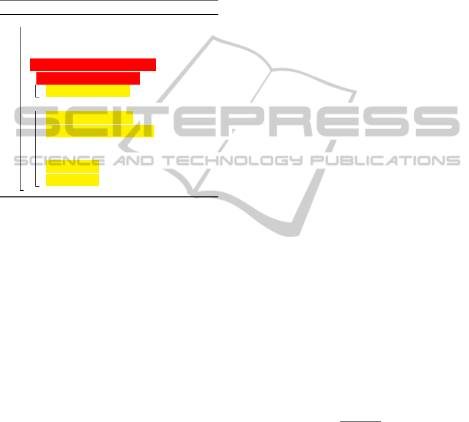
a.Topological path found. b.Second topological step.
Figure 5: Steps of a topological path.
These costs make the cost of a path (C
path
) com-
putation possible (see (2)).
C
path
=
∑
n
i, j
∈path
C
n
i, j
+
∑
e
k
∈path
C
e
k
(2)
Then the Topological planner explores the graph
(line 4) thanks to a Dijkstra algorithm (Dijkstra, 1959)
to find the less expensive Topological path between
start and goal nodes. This Topological path is used
to split the trajectory in Topological steps (line 5),
each step corresponding to a place to cross (a edge
of Topological path) and a Border to reach (a node of
topological path). Fig. 5.a shows the Topological path
found in the environment of Fig. 3.a. Fig. 5.b focus
on the edge and the node corresponding to the second
step of this path.
3.2.2 Fine Planning
This planning stage consists in finding the concrete
geometrical path. To do so, each Topological step is
used to define a milestone configuration within the
border to reach (line 6-7). Then, accordingly to the
semantic information of the place to cross, we adapt
the geometric path planning strategy. Indeed, the aim
of our architecture is to be able to choose the best geo-
metric planning method among a set of available ones
for each step. For now, we use two geometric plan-
ning strategies. These two strategies deal with the
two distinct geometric environment models (Obsta-
cles and Free space description). Depending on the
semantic attribute describing the place’s cluttering,
the geometric planner can perform an A* algorithm
(when the place is cluttered) on the part of the octree
corresponding to the step’s place to set intermediate
milestones within the step. When all the milestones
have been defined, the Local planner guides the user
toward the next milestone. It computes a linear in-
terpolation between current configuration and mile-
stone’s configuration, and uses this interpolation to
apply a torsor on a haptic device.
3.2.3 Coarse and Fine Planning Organization
The coarse and fine planning are used to manage the
whole planning. The Topological path and its steps
are concepts allowing saving the necessary informa-
tion for each planning layer. When the Topological
path is found and the Topological steps are defined,
the steps information is used by the Semantic planner
to set the geometric layer accurately.
3.3 Process Monitoring
The Topological path and its steps are concepts al-
lowing the different planning layers sharing the infor-
mation. When the Topological path is found and the
Topological steps are defined, the step information is
used by the Semantic planner to accurately set the ge-
ometric layer.
Algorithm 3 shows how the planning layers are
involved to monitor the planning process. While the
user is performing the task, he is guided toward the
next milestone configuration thanks to the haptic de-
vice. This next milestone is updated while the user
moves along the path. On the geometric layer, the
next milestone is set to the Local planner for the guid-
ance computation when the current one is considered
as reached (line 11-12). The goal is considered as
reached when the distance between the goal and the
current position is smaller than θ
d
. On the topologi-
cal layer, the milestone is a Border, so even if the user
is guided toward a geometric configuration set within
the Border, the milestone is considered as reached as
soon as the user enters the Border. When the target
Border is reached (line 2), the next Topological step
is used to set the Local planner (line 7-9), except if
the current step was the last one. In this case, the
last milestone must be reached to consider the task as
achieved (line 3-5).
3.4 Control Sharing Aspects
The planner provides user with a guidance torsor
through the haptic device used for object manipula-
tion. This Local planner computes the guidance tor-
sor.
For each layer of such a planner architecture, spe-
cific ways to share control can be proposed as shown
in Table 2.
In Table 2 it appears that the intent prediction for
the geometric layer is directly linked to the authority
sharing of topological layer. Indeed, within a Place,
the set of potential goals to get out of this Place is
made of the corresponding Borders. The intent pre-
diction is made with geometric movement and geo-
ICINCO2014-11thInternationalConferenceonInformaticsinControl,AutomationandRobotics
94
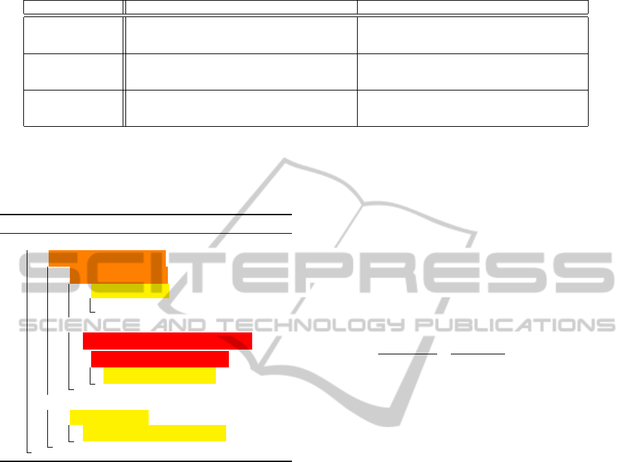
Table 2: Interaction means on the diferent layers.
Authority sharing Intent detection
Semantic
layer
Learn from users action new semantics information or
means to deal with them to accurately set the topological
and geometric planners
Interpret planning query expressed in natural language
(assemble this part on this one, bring this object on this
one,...)
Topological layer
Check if user agrees with the proposed topological path.
Trying to predict his intents on the topological layer
(which place he is targeting)
Learn the kind of paces the user prefers to cross to advan-
tage them during the topological path planning process
Geometric layer
Dynamically balance the authority on the object manip-
ulation (between human and automatic planner) by mod-
ulating the automatic planner guidance norm
Find the targeted next place to redefine the geometric
planner goal
metric information on Borders. The re-planning is
made by the Topological planner for a new Topologi-
cal path definition.
Algorithm 3: Process Monitoring.
1 begin
2 if Topological step = achieved then
3 if current step = last step then
4 if Milestone reached then
5 achieved = true;
6 else
7 set next Topological step in Local planner ;
8 if Topological step’s Place cluttered then
9 run A* on Topological step ;
10 else
11 if Milestone reached then
12 set next milestone to Local planner ;
The same logic applies for the intent prediction
of the topological layer and the authority sharing of
the semantic layer. Cost functions of (1) may be
learned from the places the user prefers to cross. In-
deed the preferred places attributes can be identified
from all the re-planning done due to users action. The
new cost values defined with these functions will thus
change all the incoming topological re-planning.
The control sharing of the proposed planning ar-
chitecture is focused on the geometric and topological
layers. We implemented A H-mode from (Flemisch
et al., 2012) for geometric authority control. We also
developed an intent prediction inspired from (Dragan
and Srinivasa, 2013) to make the topological path re-
planning available.
3.4.1 Authority Sharing
To share authority, we chose to use a strategy inspired
from H-mode introduced in (Flemisch et al., 2012).
This strategy aims at modulating the guidance torsor
G norm according to the user’s involvement as shown
in equation 3.
G
user
= g
mod
.G (3)
Where g
mod
is a measure of user’s involvement
from g
mod
min
(not involved) to 1 (strongly involved).
The lower limit g
mod
min
is chosen to keep the user
aware of automatic planner state as suggested by
(Marayong et al., 2003). In our application of H-
mode, we chose to compute g
mod
i
on each process
loop i from the scalar product of instantaneous guid-
ance force (
−→
g
i
) by the instantaneous movement direc-
tion (
−→
m
i
) as shown in equation 4.
g
mod
i
=
1 − g
mod
min
2
−→
g
i
.
−→
m
i
k
−→
g
i
kk
−→
m
i
k
+ 1
+ g
mod
min
(4)
The coefficient obtained with 4 is filtered to obtain
a smooth transfer of the authority with g
f mod
i
compu-
tation given in equation 5.
g
f mod
i
= α
mod
.g
f mod
i−1
+ (1 − α
mod
)g
mod
i
(5)
Where α
mod
is chosen from 0 to 1 accordingly to
the loop rate and the transfer time needed. The g
f mod
i
coefficient obtained is applied to equation 3 to have
our effective authority control given in equation 6.
G
user
i
= g
f mod
i
G
i
(6)
3.4.2 Intent Prediction
Algorithm 4 shows the process used to define if a
coarse re-planning is necessary or not. On line 2, if
the user is not following the guidance (angle between
guidance direction and movement direction greater
than threshold angle and movement amplitude greater
than a given threshold), it means the user does not
agree with the proposed path. He may have found an-
other one or at least needs a new proposal.
To deal with it, the intent prediction we use al-
lows us to define, in a step, for each border of the
current Place, the probability that the user is target-
ing it (line 3). These probabilities are used to define
if the user is targeting another border than the one de-
fined in his current step (line 4). In this case a new
AMulti-layerApproachforInteractivePathPlanningControl
95
Algorithm 4: Intent prediction and replanning.
1 begin
2 if user’s movement 6= guidance then
3 compute Borders’ probabilities ;
4 if prediction 6= proposal then
5 coarse planning;
6 set first Topological step in Local planner ;
7 if Topological step’s Place cluttered then
8 run A* on Topological step ;
B
1
B
2
−→
m
i
×
×
×
C
1
C
2
S
i
×
×
N
1
N
2
Figure 6: Border representative point problem.
topological path is defined taking into account user’s
will.
To manage it, we decided to adapt Dragan’s strat-
egy (Dragan and Srinivasa, 2013) using the set of bor-
der of the current step’s place as the set of potential
goals. Indeed, to predict user’s intent, Dragan com-
putes probabilities for all potential goals thanks to a
scalar product of the movement
−→
m
i
by the goal direc-
tion
−−→
S
i
G
n
(where S
i
is the current position and G
n
the
position of n
th
goal). In our simulations, the potential
goals (the borders) are not punctual. Thus the point
chosen to compute the scalar product must be care-
fully chosen. Indeed, as shown in Fig. 6, if the cen-
ters C
i
of borders B
i
are taken as representative points,
the probability to target borders B
1
and B
2
will be the
same. However, it seems that B
2
is more suited to the
user. To deal with this issue, we chose to select the
borders’ nearest points N
i
of the movement axis.
With such elements, the probability that the border
B
j,k
is targeted is given in (7) where a scalar product
is scaled to fit between 0 and 1.
With such elements, the probability that the border
B
j,k
is targeted is given in equation 7 where a scalar
product is scaled to fit between 0 and 1.
P(B
j,k
) =
1
2
−→
m
i
.
−−−→
S
i
N
j,k
i
k
−→
m
i
kk
−−−→
S
i
N
j,k
i
k
+ 0.5 (7)
Fig. 7 is an example of the points chosen for intent
prediction in place P
4
where S
i
is the instantaneous
position on sample i,
−→
m
i
its movement direction, and
N
j,k
i
the point chosen to consider border B
j,k
. In this
example, the borders classified by probability to be
targeted are: B
4,10
, B
4,9
, B
4,8
and B
4,6
.
×
S
i
N
4,6
i
N
4,9
i
N
4,8
i
N
4,10
i
×
×
×
×
−→
m
i
Figure 7: Border probability computation elements
When the probability of all the borders have been
computed, if the following condition of (8) is satis-
fied, a new topological path computation in done.
max(P(B
i, j
))–P(B
step
) ≥ θ
replanning
(8)
Where P(B
step
) is the probability computed for
the border chosen as goal of the current step and
θ
replanning
is the threshold used to decide if a topo-
logical re-planning is needed or not.
3.4.3 Coarse Re-planning
When a coarse re-planning is necessary (line 5 of
Algorithm 4) the start node of the topological graph
is updated to match with the current object posi-
tion. The borders’ costs are also updated to add costs
C
n
k,l
i
corresponding to the intent prediction (see (2)).
These new costs direct the next topological graph
exploration toward the user’s targeted border. The
new topological path computation is done adding new
costs C
n
k,l
i
to the nodes linked to the borders. The
costs added are chosen accordingly to the correspond-
ing borders as given in (2).
C
n
k,l
i
= k
max(P(B
i, j
))–P(B
k,l
)
max(P(B
i, j
))
if B
k,l
6= B
step
C
n
k,l
i
= C
h
if B
k,l
= B
step
(9)
Where k is a multiplicative coefficient and C
h
a
specific cost used to avoid the border of previous
Topological path when computing a new one.
These new costs, being heavy on the previously
chosen border, and light on the high probably targeted
ones will tend to explore paths through user’s targeted
borders and thus define a topological path crossing
one of these borders.
3.5 Interactive Path Planning
Simulation
Algorithm 5 summarizes the operations made for the
interactive path planning. First, an initialization pro-
cess including environment building and first coarse
ICINCO2014-11thInternationalConferenceonInformaticsinControl,AutomationandRobotics
96
planning is processed (line 2-7. Then, the proper
interactive planning is done in a loop (line 9-14).
This loop includes the performed trajectory record-
ing (line 9), the user’s intent prediction and the re-
planning to fit with his intent (line 11), the process
monitoring (line 12) and the guidance modulation and
update (line 13-14).
Algorithm 5: Interactive planning simulation.
1 begin
2 build environment model;
3 coarse planning;
4 achieved = f alse;
5 set first Topological step in Local planner ;
6 if Topological step’s Place cluttered then
7 run A* on Topological step ;
8 while achieved = f alse do
9 record sample configuration ;
10 compute user’s movement direction ;
11 intent prediction and replanning;
12 process monitoring;
13 update authority ;
14 update guidance ;
4 IMPLEMENTATION
We implemented our proposed path planning and
environment modeling architecture in Virtools
TM
4.1
software through libraries developed in C++ lan-
guage. We developed 3 distinct libraries: 2 au-
tonomous libraries corresponding to environment
model and path planner and an interface library.
4.1 Environment Representation Built
The environment model is implemented in a dedi-
cated library interfaced to Virtools
TM
with a specific
library.
The environment representation we use is made of
4 models:
• The objects of the environment represented
through meshes and positioning frames. To build
this part of environment model, we use the CGAL
project (CGAL, 2014). Semantic attributes are at-
tached to the objects. One of them describes if
the object is fixed or not to be able to exclude the
moving ones while identifying the places (static
mapping of the environment).
• The free space description through an octree de-
composition of the 3D scene (in this case also, the
nodes colliding with fixed object are distinguished
from those colliding with only moving objects)
• The topological graph to model the places con-
nectivity (the graph’s nodes are the borders, and
the edges the places)
• The set of places and their borders. We de-
fined some procedures to automatically identify
the places from the octree structure. The semantic
attributes are characters strings. Their attachment
to the places is manually made, choosing for each
place the right attributes among a set of available
ones. One attribute is automatically set: ”clut-
tered” if the place contains moving obstacles
The attributes available in our simulations allow
describing the level of complexity of a place as ”low”,
”average”, ”high”, and ”very high”. Another attribute
is used to define if a place is ”cluttered”. Finally,
”square”, ”triangular”, ”round” and ”pentagonal” at-
tribute can be set to describe place’s shape.
4.2 Planner Implementation
The planner is also implemented in a dedicated library
and interfaced to VirtoolsTM using the same interface
library used to interface the environment.
4.2.1 Planning Classes
Four classes had been defined corresponding to the
four planners. Each of these planner classes deals
with an environment model. The local planner pro-
vides the user with the guidance. The geometric plan-
ner finds, if necessary, a path on the octree. The topo-
logical planner explores the topological graph to build
the path and the steps managed by the local and the
geometric planner. The semantic planner coordinates
the whole planning process, asking the topological
planner for the topological path and planning which
strategy will be used on the geometric layer.
For the weights computation, we defined the func-
tion of (1) assigning the weights as given in (10).
C
n
i, j
=
C
complexity
2
C
e
k
= d
k
.C
complexity
(10)
Where C
complexity
sums two costs:
• the first one is set according to the traversability
of the involved places 0, 0.5, 1 and 5 for low, av-
erage, high and very high complexity.
• the second one is set according to the shape at-
tribute: 0 if empty, 0.5 if the shape match with the
handled object’s shape, and 5 if not.
AMulti-layerApproachforInteractivePathPlanningControl
97
4.2.2 Control Sharing Classes
Two main classes improve the planner for the con-
trol sharing. The first one is related to the Author-
ity Controller. It aims at modulating the guidance
norm according to the user’s involvement. It allows
user to feel free when he is exploring others ways.
The second one is the Intent Predictor. It detects the
user intents to compute a new Topological Path when
the user goes away from the proposed one. These
two classes and there computation are strongly based
on the instantaneous movement computation made
thanks to the Trajectory Step Trajectory.
The geometric authority sharing is set as follow:
• the minimal guidance norm is set to 10% of the
nominal norm. Thus the g
mod
min
parameter of
equation 4 is set to 0.1.
• the guidance modulation filter parameter α
mod
of
equation 5 is set to 0.9 to process the filtering on
some twenty samples
4.2.3 Processes and Threads
The guidance submitted to user being provided in
real-time through a haptic device, the corresponding
computations are done in the main thread of simula-
tion. This inclusion in the simulation loop updates the
guidance about 60 times per second.
The intent prediction and the new topological path
computation are run when needed on a dedicated
thread to not disturb the main thread and thus not de-
crease the sample rate. Both processes are synchro-
nized thanks to flags notifying states changes.
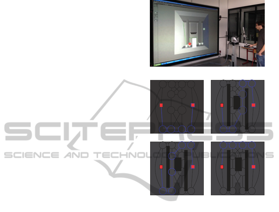
5 SIMULATIONS AND RESULTS
The following simulations were implemented on our
VR platform (Fillatreau et al., 2013) (see Fig. 8). The
VR devices used here are a large screen using passive
stereoscopy for the 3D visualization and immersion,
an AR Track system for the user view-point capture
and a Virtuose 6D 35-45 as haptic device for the part
handling.
The first simulation is a 3D instance of the 2D ex-
ample used to illustrate the principles of our planning
strategy. It has been used for development and al-
lowed to test the collaboration of the planners. The
second simulation shows a richer semantics of the en-
vironment (semantic attributes that describe the shape
of objects and places). This has allowed showing
how the control of the planning process, thanks to the
semantic information, increases the reliability of the
planned path while reducing the processing time.
Figure 8: Simulation on VR platform.
S G
B
1,5
B
2,7
B
1,6
B
2,8
B
3,5
B
3,7
B
4,6
B
4,8
B
3,9
B
3,10
B
4,9
B
4,10
P
1
P
1
P
1
P
2
P
3
P
4
P
5
P
7
P
8
P
6
P
9
P
10
P
3
P
3
P
3
P
3
P
4
P
4
P
4
P
4
P
2
P
2
S G
T
1,5
T
2,7
T
1,6
T
2,8
T
3,5
T
3,7
T
4,6
T
4,8
T
3,9
T
3,10
T
4,9
T
4,10
P
1
P
1
P
1
P
2
P
3
P
4
P
5
P
7
P
8
P
6
P
9
P
10
P
3
P
3
P
3
P
3
P
4
P
4
P
4
P
4
P
2
P
2
a.Environment 1. b.Environment 2.
S G
T
1,5
T
2,7
T
1,6
T
2,8
T
3,5
T
3,7
T
4,6
T
4,8
T
3,9
T
3,10
T
4,9
T
4,10
P
1
P
1
P
1
P
2
P
3
P
4
P
5
P
7
P
8
P
6
P
9
P
10
P
3
P
3
P
3
P
3
P
4
P
4
P
4
P
4
P
2
P
2
S G
T
1,5
T
2,7
T
1,6
T
2,8
T
3,5
T
3,7
T
4,6
T
4,8
T
3,9
T
3,10
T
4,9
T
4,10
P
1
P
1
P
1
P
2
P
3
P
4
P
5
P
7
P
8
P
6
P
9
P
10
P
3
P
3
P
3
P
3
P
4
P
4
P
4
P
4
P
2
P
2
c.Environment 3. d.Environment 4.
Figure 9: Experimental environments.
5.1 First Simulation
5.1.1 Simulation Scene
To test the multi-layer structure on the laboratory’s
VR platform, the environment used is a 3D instance
of the environment described in section 3. This en-
vironment is a cubic workspace with four obstacles
cluttering the scene (3 fixed and 1 moving). Different
environment configurations have been tested moving
the fixed obstacles to change the complex passages lo-
cations (O
1
and O
2
are moved vertically and O
3
hor-
izontally). The corresponding topological graphs are
given in Fig. 9. This figure also illustrates the plan-
ning query in these environments. It aims at bring-
ing a piece from a start point S in place P
1
to a goal
point G in place P
2
. The topological paths found by
the topological planner are also displayed in bold blue
lines in the topological graphs.
5.1.2 Path Planning
Fig. 10 shows the real path computed in the environ-
ICINCO2014-11thInternationalConferenceonInformaticsinControl,AutomationandRobotics
98
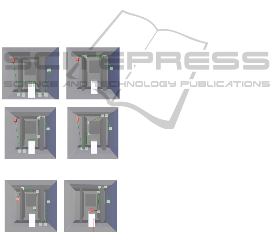
ment illustrated in Fig. 9. The object to move
is the red cube and the targeted goal is the green one.
The path is displayed in green. The paths on place P
3
avoid mobile obstacle O
4
thanks to the A* algorithm
performed on this cluttered place. To find such paths,
the computational time for the Dijkstra algorithm
in the topological graph was about 1ms, and the
A* algorithm when necessary to cross the cluttered
place took from 50ms to 750ms depending on the
path to find. Thus, the whole path is find in less than
1s when using the A* algorithm alone without any
semantics or topology planning process takes about
3.5s without avoiding complex passages (in this case
the past computed is the shortest but not the easiest to
perform).
0.10cm
a.Environment 1. b.Environment 2.
c.Environment 3. d.Environment 4.
Figure 10: Planning results.
a.Re-planning in step 1. b.Re-planning in step 3.
Figure 11: Topological re-planning in environment 1.
5.1.3 Path Re-planning
Fig. 11 illustrates the topological re-planning includ-
ing real-time detection of user’s intent. In Fig. 11.a, in
the first step, the user seems to prefer the narrow pas-
sage. Detecting it, the topological path is recomputed
taking into account this intent. In Fig. 11.b, the user
doesn’t follow the guidance along the A* path in the
third step. Thus, the topological planner computes a
new topological path. The path re-planning including
A* process is done in less than 150ms in this case.
5.2 Second Simulation
5.2.1 Simulation Scene
Our simulation scene (see Fig. 12) is made of a cubic
workspace divided in three large places by two walls.
The wall in the foreground is an obstacle with four
holes. Each hole has a characteristic shape (square,
triangular, round and pentagonal). The wall in the
background is an obstacle leaving a passage on each
side (a large one on the left and a narrow one on the
right). A moving obstacle clutters the place between
these two walls.
The topological places of this environment are:
the three large places, the two passages around the
background wall, and the holes through the fore-
ground wall (each hole corresponds to a place). The
semantic attributes attached to the places are: ”low
complexity” for the three large places; ”high com-
plexity” for the large passage around the background
wall, and ”very high” for the narrow one. Attributes
are also set to the wall holes to describe their shape
(”square”, ”triangular”, ”round” and ”pentagonal”).
The additional ”cluttered” semantic attribute is as-
signed to the places containing moving objects.
The planning query here consists in passing the
two walls to move the shaped object (in red) from one
side of the cube to the other.
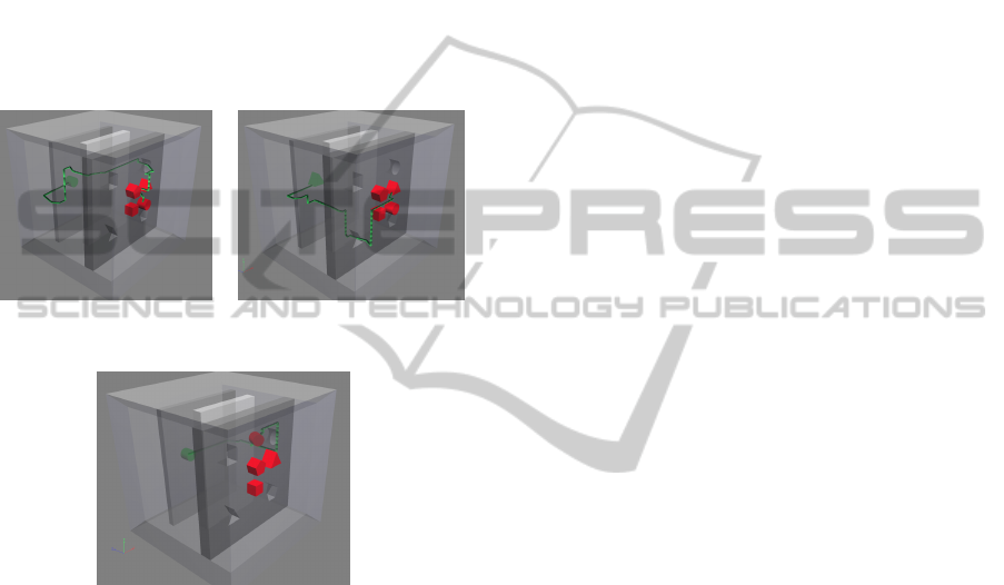
5.2.2 Path Planning
Fig. 12 shows the path computed with our proposed
architecture. Fig. 12.a shows the path planned for the
red cylindrical object, and Fig.12.b the path planned
for the triangular one. In both cases, a path is found,
and the computed path crosses the wall in the fore-
ground through the hole having the same shape as the
moved object. Furthermore, the computed path goes
through the large passage beside the wall in the back-
ground rather than the narrow one.
The computational time to find these paths is 1s
when moving the triangular object and 7s when mov-
ing the cylindrical one. The A* search is more com-
plex for the cylinder. In Fig. 12.b, after the triangu-
lar moved object has crossed the triangular hole, the
path through the large passage besides the wall in the
background is quite simple. The path computed for
the cylinder is more complex. When the cylinder has
crossed the round hole, it is located on the wrong side
of the background wall to reach the large passage.
AMulti-layerApproachforInteractivePathPlanningControl
99
We compared our results to the results obtained
using the A* planning algorithm. The processing
times obtained were 24s and 26s for the triangle ob-
ject and the cylinder respectively; in both cases, the
A* algorithm failed to find a feasible path as the pro-
posed hole to get through the wall in the foreground
had the wrong shape.
These results show the advantage brought by our
architecture; controlling a classical geometrical path
planner using the semantic and topological informa-
tion leads to improve the planning results qualitatively
(success vs failure), while reducing drastically pro-
cessing times.
a.Path for cylinder. b.Path for triangle.
Figure 12: Planning results.
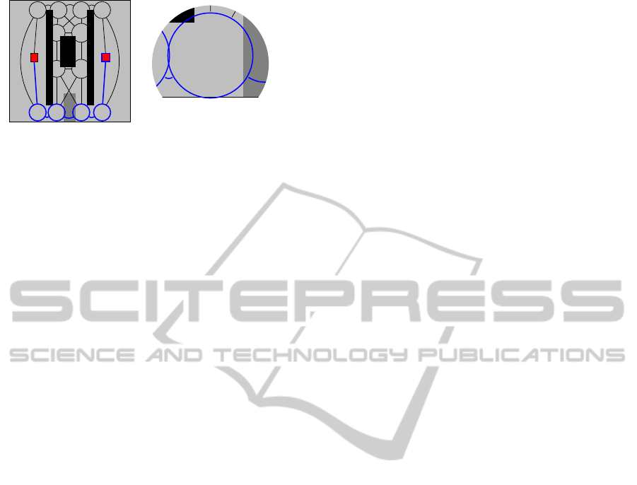
Figure 13: Coarse re-planning with cylinder.
5.2.3 Path Re-planning
Fig. 13 illustrates the topological re-planning in the
case of the cylinder manipulation. Here, the user does
not follow the haptic guidance along the A* path be-
tween the two walls, and targets the narrow passage to
perform a simpler path. Thus, the topological planner
computes a new topological path, through the narrow
passage instead of the large one, according to the user
intent. The path re-planning (topological re-planning
and geometrical A* re-planning) is done in less than
2s in this case.
6 CONCLUSION
This paper presents a novel multi-layer architecture
for interactive path planning in VR simulations. This
architecture is based on a multi-layer environment
model and a multi-layer planner. Each layer deals
with specific information (semantic, topological and
geometric). The contribution of such an architecture
is two-fold :
• First, it provides the user with real-time manip-
ulation guidance thanks to path planning involv-
ing the semantic and topological information. The
path planning process is accelerated by splitting
the path in steps and then by adapting the geo-
metric planning strategy to the local complexity
of each step.
• Second, it integrates efficiently a human in the
loop: path re-planning is computed based on real-
time user’s intent detection and motion control is
shared by the user and the planner.
The interest of such a planner architecture had
been demonstrated here with semantic information of
the environment based on ”complexity”, ”shape” and
”clutter”. This information allowed this novel archi-
tecture to deal efficiently with an abstract example us-
ing only simple geometrical path planning techniques.
However, real manipulation task for industrial
processes involves more complex semantic informa-
tion (functional surface, multi-physics interactions,
surfaces or material properties). Future work will be
done to further define both the meaningful semantic
information needed for such tasks and the correspond-
ing planning strategies. The proposed architecture
meets the requirements for such semantic informa-
tion. For instance, in assembly tasks, sliding motions
are commonly used. We are planning to develop in-
teractive geometric path planning methods with con-
tact. We also plan to enrich the topological and se-
mantic layer of our environment model in order to use
our global architecture to choose to interactively plan
paths with or without contact according to the func-
tional context of the assembly tasks (or subtasks) to
be performed.
Moreover, with an accurate semantic description,
such a planner structure seems also well suited for off-
line path planning allowing to rapidly find hard pas-
sages using the topological planning and to rapidly
adapt the geometric planning strategy according to the
local planning context.
REFERENCES
Aarno, D., Ekvall, S., and Kragic, D. (2005). Adaptive vir-
tual fixtures for machine-assisted teleoperation tasks.
In International Conference on Robotics and Automa-
tion, ICRA. Proceedings, pages 1139–1144. IEEE.
Abbink, D. A. and Mulder, M. (2010). Neuromuscular anal-
ICINCO2014-11thInternationalConferenceonInformaticsinControl,AutomationandRobotics
100

ysis as a guideline in designing shared control. Ad-
vances in haptics, 109:499–516.
Ahmadi-Pajouh, M. A., Towhidkhah, F., Gharibzadeh, S.,
and Mashhadimalek, M. (2007). Path planning in the
hippocampo-prefrontal cortex pathway: An adaptive
model based receding horizon planner. Medical hy-
potheses, 68(6):1411–1415.
Anderson, S., Peters, S., Iagnemma, K., and Overholt, J.
(2010). Semi-autonomous stability control and hazard
avoidance for manned and unmanned ground vehicles.
Technical report, DTIC Document.
CGAL (2014). CGAL, Computational Geometry Algo-
rithms Library. http://www.cgal.org.
Dijkstra, E. W. (1959). A note on two problems in connex-
ion with graphs. Numerische mathematik, 1(1):269–
271.
Dragan, A. D. and Srinivasa, S. S. (2013). A policy blending
formalism for shared control. International Journal of
Robotics Research.
Fagg, A. H., Rosenstein, M., Platt, R., and Grupen, R. A.
(2004). Extracting user intent in mixed initiative tele-
operator control. In Proc. American Institute of Aero-
nautics and Astronautics Intelligent Systems Technical
Conference.
Fillatreau, P., Fourquet, J.-Y., Le Bolloch, R., Cailhol, S.,
Datas, A., and Puel, B. (2013). Using virtual reality
and 3d industrial numerical models for immersive in-
teractive checklists. Computers in Industry.
Flemisch, F., Heesen, M., Hesse, T., Kelsch, J., Schieben,
A., and Beller, J. (2012). Towards a dynamic bal-
ance between humans and automation: authority, abil-
ity, responsibility and control in shared and coopera-
tive control situations. Cognition, Technology & Work,
14(1):3–18.
Ladeveze, N., Fourquet, J.-Y., and Puel, B. (2010). Inter-
active path planning for haptic assistance in assembly
tasks. Computers & Graphics, 34(1):17–25.
LaValle, S. (2006). Planning algorithms. Cambridge Uni-
versity Press.
Li, M. and Okamura, A. M. (2003). Recognition of op-
erator motions for real-time assistance using virtual
fixtures. In 11th Symposium on Haptic Interfaces for
Virtual Environment and Teleoperator Systems. HAP-
TICS. Proceedings., pages 125–131. IEEE.
Loizou, S. G. and Kumar, V. (2007). Mixed initiative con-
trol of autonomous vehicles. In International Confer-
ence on Robotics and Automation., pages 1431–1436.
IEEE.
Lozano-Perez, T. (1980). Spatial planning: A configuration
space approach. IEEE Transactions on Computers,
100(2):108–120.
Marayong, P., Li, M., Okamura, A. M., and Hager, G. D.
(2003). Spatial motion constraints: Theory and
demonstrations for robot guidance using virtual fix-
tures. In International Conference on Robotics and
Automation, Proceedings. ICRA, volume 2, pages
1954–1959. IEEE.
Ta
¨
ıx, M., Flavign
´
e, D., and Ferr
´
e, E. (2012). Human in-
teraction with motion planning algorithm. Journal of
Intelligent & Robotic Systems, 67(3-4):285–306.
Weber, C., Nitsch, V., Unterhinninghofen, U., Farber, B.,
and Buss, M. (2009). Position and force augmentation
in a telepresence system and their effects on perceived
realism. In EuroHaptics conference, 2009 and Sym-
posium on Haptic Interfaces for Virtual Environment
and Teleoperator Systems. World Haptics 2009. Third
Joint, pages 226–231. IEEE.
You, E. and Hauser, K. (2012). Assisted teleoperation
strategies for aggressively controlling a robot arm
with 2d input. Robotics: Science and Systems VII,
page 354.
Yu, W., Alqasemi, R., Dubey, R., and Pernalete, N. (2005).
Telemanipulation assistance based on motion inten-
tion recognition. In International Conference on
Robotics and Automation, ICRA Proceedings, pages
1121–1126. IEEE.
AMulti-layerApproachforInteractivePathPlanningControl
101
