
Development of Gait Measurement Robot
for Prevention of Falls in the Elderly
Ayanori Yorozu
1
, Mayumi Ozawa
1
and Masaki Takahashi
2
1
School of Science for Open and Environmental Systems, Keio University,
3-14-1 Hiyoshi, Kohoku-ku, Yokohama 223-8522, Japan
2
Department of System Design Engineering, Keio University, 3-14-1 Hiyoshi, Kohoku-ku, Yokohama 223-8522, Japan
Keywords: Gait Measurement, Omnidirectional Mobile Robot, Kalman Filter, Laser Range Sensor.
Abstract: To prevent falls in the elderly, gait measurements such as several-meters walking test and gait trainings are
carried out in community health activities. To evaluate the risk of falling of the participant, it is necessary to
measure foot contact times and positions so that the stride length of each leg and the walking speed can be
used as evaluation parameters. However, the conventional measurement systems are difficult to install for
use in community health activities because of their scale, cost and constraints of the measurement range. In
this study, we propose a novel gait measurement system which uses an autonomous mobile robot with laser
range sensor (LRS) for a long-distance walking test in a real living space regardless of detection range of
sensor. The robot sequentially estimates its own pose and acquires the position of both legs of the
participant. The robot leads the participant from the start to the goal of the walking test while maintaining a
certain distance from the participant. Then, the foot contact times and the positions are calculated by
analyzing estimated position and speed of each leg. From the experimental results, it was confirmed that the
proposed robot could acquire the foot contact times and positions.
1 INTRODUCTION
With our society rapidly aging, there is a worry that
the burden on families who have members in need of
nursing care will increase. Falling is one of the main
factors that cause elderly people to require nursing
care (WHO, 2008), and one-third of community-
dwelling individuals aged over 75 years will
experience at least one fall a year (Tinetti, et al.,
1988).
To prevent falls in the elderly, gait measurements
and trainings are carried out in community health
activities. As shown in Figure 1 (a), one of the
representative gait measurement to evaluate motor
function is a several-meters walking test. In addition,
it has been reported that elderly people at high risk
of falling decrease a dual-task performance
including not only motor function but also cognitive
function (Melzer and Oddsson, 2004), (Yamada, et
al., 2011). As shown in Figure 1 (b), to enhance not
only motor function but also cognitive function, gait
trainings where the participant steps on the target
square following instructions displayed on a screen
have been proposed (Schoene, et al., 2013),
(Yamada, et al., 2012). To evaluate the risk of
falling of the participant, it is necessary to measure
foot contact times and positions so that the stride
length of each leg and the walking speed can be used
as evaluation parameters.
Generally, force plates (Melze, et al., 2007) or
three-dimensional motion analysis devices (Davis, et
al., 1991) have been used in gait analysis. However,
it is difficult to install these devices for use in
(a) 10 m walking test to
evaluate motor function
(Kakamigahara, 2007)
(b) Home-based step training
to enhance dual-task
performance (Schoene, et al.,
2013)
Figure 1: Example of gait measurements and trainings in
community health activities.
127
Yorozu A., Ozawa M. and Takahashi M..
Development of Gait Measurement Robot for Prevention of Falls in the Elderly.
DOI: 10.5220/0005058001270135
In Proceedings of the 11th International Conference on Informatics in Control, Automation and Robotics (ICINCO-2014), pages 127-135
ISBN: 978-989-758-040-6
Copyright
c
2014 SCITEPRESS (Science and Technology Publications, Lda.)
community health activities because of their scale
and cost. Consequently, measurements during
community health activities are often carried out by
observation using a stopwatch, making it difficult to
measure foot contact times and positions. Therefore,
a low-cost, easy-to-use gait measurement system is
required. Previously, we proposed gait measurement
systems using a laser range sensor (LRS)
(Matsumura, et al., 2013), (Yorozu and Takahashi,
2014). However, a system with a stationary LRS
cannot be used for long-distance walking tests
because its measurement range is limited by the
detection range of the LRS.
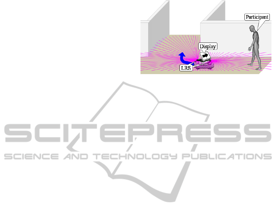
To deal with these problems, we propose a novel
gait measurement system which uses an autonomous
mobile robot for a long-distance walking test in a
real living space. Figure 2 shows an image of the
proposed gait measurement robot. The robot
sequentially estimates its own pose (localization)
and acquires the position of both legs of the
participant based on the distance data from the
sensors. The robot leads the participant from the
start to the goal of the walking test while
maintaining a certain distance from the participant.
Then, foot contact times and positions are calculated
by analyzing the estimated position and speed of
each leg. By maintaining a certain distance from the
participant, the robot can make measurements for
the long-distance walking test regardless of the
detection range of the sensor. In addition, as shown
in Figure 2, by leading the participant, the robot can
provide instructions to the participant on how to
make the movement, and we expect that the robot
will also be able to evaluate not only motor function
but also cognitive function of the participant from
the response such as reaction time to the instructions.
In this paper, to verify the accuracy of the foot
contact times and positions measured by the
proposed robot, straight walking tests with young
people were carried out. The foot contact times and
positions acquired by the proposed system were
compared with the result measured using a three-
dimensional motion analysis system (VICON).
2 CONCEPTS
The proposed gait measurement robot sequentially
process localization and acquires leg positions from
sensor data and command speed determination to
maintain a certain distance from the participant
based on the estimated its own pose and leg
positions. To define the field for the walking test and
to estimate its own pose during the walking test, the
Figure 2: Image of the proposed gait measurement robot.
robot builds a map of the field based on
simultaneous localization and mapping (SLAM)
(Thrun, et al., 2005) before the walking test. In
environment recognition during movement, it is
desirable to be able to acquire high accuracy
distance data over a wide range. With this in mind,
LRSs are generally used in autonomous mobile
robots. In addition, a method for calculating the leg
positions based on the characteristic leg patterns
from the LRS scan data has been proposed (Bellotto
and Hu, 2009). A method to acquire the posture of
the pedestrian based on the RGB data from a camera
or RGB-Depth data from a KINECT has been
proposed (Shotton, et al., 2011), (Ratsamee, et al.,
2012). In this paper, because we intend to track both
legs and measure the foot contact times and
positions, LRSs that can obtain distance data over a
wide range by a single unit are used to recognize the
environment for localization and to acquire the leg
positions. In future, when we need to measure other
walking parameters, we will implement sensor
fusion with other sensors to match the measurement
items.
The robot is required a smooth movement
according to the participant’s motion. Additionaly,
the robot is also required to move while facing the
participant screen in order to give instructions to the
participant. To realize such movement, an
omnidirectional drive system that can control
translational and rotational motion simultaneously is
equiped and is designed to be able to put out an
average of human walking speed.
Moreover, it has been reported that elderly
people at high risk of falling tend to look close to
their body (e.g., look at their feet) and find it
difficult to recognize the surrounding environment
during walking (Yamada, et al., 2012). To allow
them to recognize the surrounding environment by
keeping their gaze in front, the robot is designed to
lead the participant while maintaining a 1.5 m
distance from them.
ICINCO2014-11thInternationalConferenceonInformaticsinControl,AutomationandRobotics
128
3 GAIT MEASUREMENT ROBOT
3.1 System Configuration
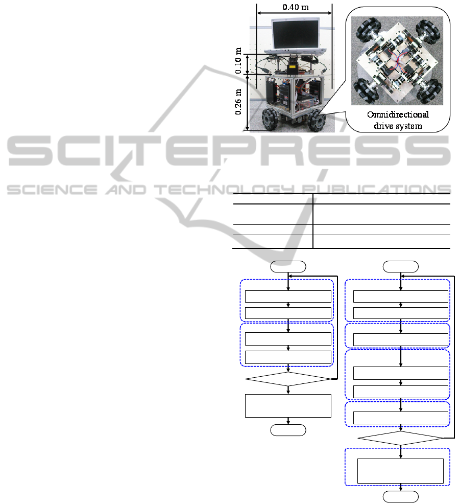
Figure 3 shows the appearance of the proposed gait
measurement robot. The robot is 0.26 m height, 0.40
m diameter and its weight is 11 kg. Two LRSs are
equipped in front and back of the robot for
recognition of the surrounding environment and gait
measurement. Table 1 shows the specification of the
LRS. In addition, the robot has an omnidirectional
drive system composed by four wheels and the
maximum speed of the robot is 2.5 m/s that is faster
than the average of human walking speed (1.4 m/s).
The wheel rotation data is able to be obtained by
encoder.
Figure 4 shows the overview of the process of
the gait measurement robot system. As shown in
Figure 5, we define two coordinate systems. One is
field coordinate system
,,Σ xy
and the other is
robot coordinate system
,,Σ xy
, where the
symbol dash indicates the robot coordinate.
As shown in Figure 4 (a), if the robot does not
have a map of the walking test field, the robot builds
a map by SLAM and determines the start and goal
positions. In this study, the robot builds a two-
dimensional occupancy grid map using the front
LRS scan data.
In the gait measurement process shown in Figure
4 (b), the robot estimates its own pose in the field
coordinate using the front LRS scan data and the
map built in advance. In addition, the robot detects
legs in the robot coordinate using the back LRS scan
data and estimates the position and velocity of both
legs in the field coordinate using the Kalman filter
with the estimated own pose. Then, velocity
command of the robot is successively determined
with the artificial potential method based on the
estimated robot pose and positions of the legs and
the goal until the participant reaches the goal
position. When the participant reaches the goal, the
robot will stop and calculate the foot contact times
and positions based on the acquired position and
velocity of the legs.
3.2 Localization with Occupancy Grid
Map
In the localization shown in Figure 4, the robot
estimates its own pose based on the wheel rotation
data of the encoders, LRS scan data and two-
dimensional occupancy grid map. The occupancy
grid map is capable of probabilistic representation
and each cell has an existence probability of the
object.
Map
k
bel p
is the occupancy of the cell at the
position
T
xyp
.
Map
k
bel p
is given depending
Figure 3: Appearance of the gait measurement robot.
Table 1: Specification of LRS (URG-04-LX-UG01,
HOKUYO AUTOMATIC CO., LTD.).
Detection range 0.02 to 5.6 m, 240 deg
Accuracy
0.06 to 1.0 m: ± 0.03 m
1.0 to 4.0 m: ± 3% of measurement
Angular resolution 0.36 deg (360 deg/1024)
Scan time
t
0.10 s/scan
(a) Mapping (b) Gait measurement
Figure 4: Overview of the process of the gait measurement
robot system.
Start
Localization
(section 3.2.1)
LRS scan
Map update
(section 3.2.2)
Finish ?
No
Ye s
Encoder measurement
Start and goal positions
determination
End
Sensing
SLAM
Start
Localization
(section 3.2.1)
LRS scan
Goal ?
No
Yes
Encoder measurement
Walking parameter
extraction
(section 3.3.3)
End
Sensing
Localization
Leg detection
(section 3.3.1)
Gait
measurement
Leg tracking
(section 3.3.2)
Navigation
(section 3.4)
Navigation
Gait analysis
DevelopmentofGaitMeasurementRobotforPreventionofFallsintheElderly
129

Figure 5: Coordinate systems of the robot and the field.
on the cell state as follows:
01
10
0
Map
k
Map
k
Map
k
bel Occupied
bel Unoccupied
bel Unknown
p
p
p
.
(1)
We set the cell size 0.03 m to estimate robot pose
with a high accuracy.
3.2.1 Localization
As shown in Figure 4, the robot estimates its own
pose using the sampling poses and those of
likelihood calculated with the LRS scan data and the
map in existence.
First, the sampling poses of the robot
,,
Robot
kth
Robot Robot
kkth
Robot
kth
x
x
y
y
p
at the time k are
calculated based on the movement of the robot
1111
T
Enc Enc Enc Enc
kkkk
xy
p
calculated from
the wheel rotation data of encoders.
0,0,0
T
Robot Robot Robot Robot
kkkk
xy
p
is a wheel
odometry calculated as follows:
1
1
1
11
1
11 1
1
cos sin 0
sin cos 0
001
Robot Robot
kk
Robot Robot
kk
Robot Robot
kk
Robot Robot
E
nc
kk
k
R
obot Robot Enc
kk k
E
nc
k
xx
yy
x
y
(2)
We set the parameters as
, , 0, 1, 2, 3
,
,0.03
th th
xy (= cell size) and
60
th
.
Then, the likelihood
,,
of the sampling
pose
,,
Robot
k
p
is calculated as follows:
1
,,
,,
n
N
l
Map
kk
n
bel
N
p
,
(3)
where
N is the number of LRS scan data which
detects an object and
,,
n
l
k
p
is the position of
the object detected by the
n-th LRS scan data
n
l in
the field coordinate.
Finally, the estimated robot pose
T
Robot Robot Robot Robot
kkkk
xy
p
at the time k is
determined as the sampling pose of maximum
likelihood.
3.2.2 Map Update
In building a field map process shown in Figure 4
(a), the map is updated based on the probabilistic
model of the LRS scan data and the estimated robot
pose.
The object existence probabilistic model of the
i
-th LRS scan data from the center of the LRS to the
object detection distance
i
l is as follows (Yamaura,
et al., 2005):
2
1/ 0
() 1
0
i
ii
l
ki
rl r l
bel r r l
else
,
(4)
where
r
is the distance from the center of the LRS.
Then, the occupancy of the cell at the position
p
is
updated with the following equation:
1
ˆ
Map Map LRS
kk k
bel bel bel
pp p
,
(5)
where
ˆ
is the likelihood of the estimated robot
pose and
LRS
k
bel p
is the object existence
probability of the LRS translated to the field
coordinate considering the estimated robot pose.
3.3 Gait Measurement with LRS
As shown in Figure 4 (b), the robot detects legs in
the robot coordinate using the back LRS scan data
and estimates the position and velocity of both legs
in the field coordinate using the Kalman filter with
the estimated own pose. After the participant reaches
the goal, the robot will stop and calculate the foot
contact times and positions based on the acquired
position and velocity of the legs.
3.3.1 Leg Detection
Leg positions at shin height are able to be calculated
by the characteristic LRS scan data pattern (Bellotto
and Hu, 2009). As shown in Figure 6, we classified
x
y
O
x
y
O
Field coordinate Robot coordinate
ICINCO2014-11thInternationalConferenceonInformaticsinControl,AutomationandRobotics
130
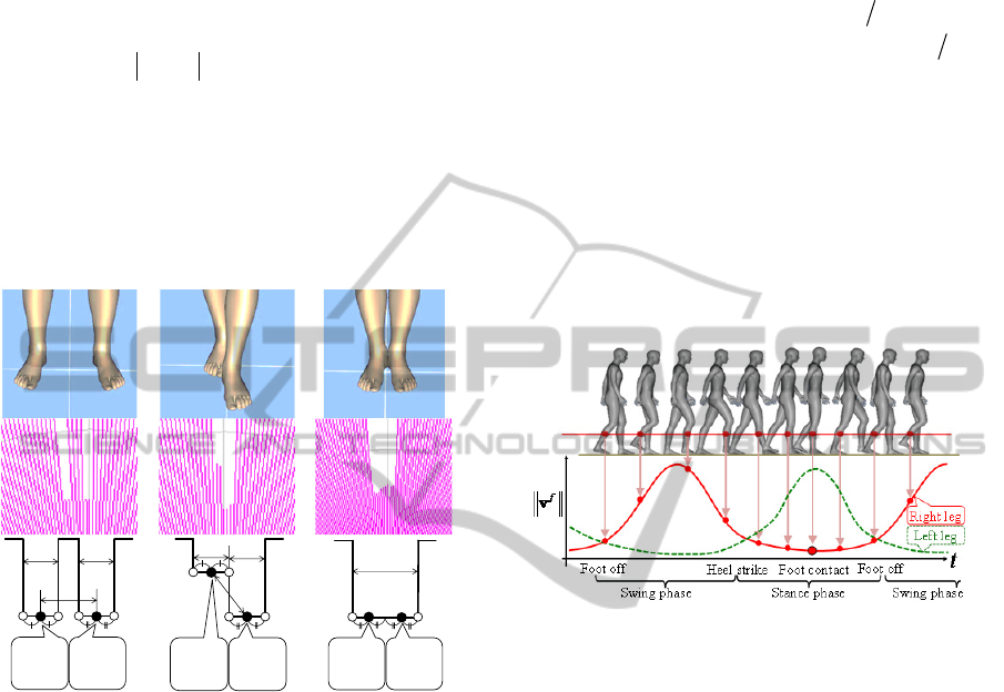
the legs into three leg patterns: LA (two Legs Apart),
FS (Forward Straddle) and SL (Single Leg).
First, to detect the three leg patterns, the vertical
edges shown in Figure 6 as a symbol “
o
” were
extracted from LRS scan data using following
equation:
1
0.1
ii
ll
,
(6)
where
i
l
is the i-th scan data from the right of an
LRS. Moreover, the detected edges are classified
into two type: left edge when
1ii
ll
and right edge
when
1ii
ll
.
In classifying the legs into the three leg patterns,
we define a, b and c which are, respectively the
(a) LA (b) FS (c) SL
Figure 6: Leg patterns extracted from LRS scan data.
thresholds of, the leg width, the maximum step
length and the width of the two legs together. Then,
the leg pattern was detected by using three leg
parameters and the combination of the arrangement
of the edges. We set these thresholds as
0.01 0.20a
,
0.10 1.0b
and
0.20 0.40c
.
Finally, left and right leg positions in the robot
coordinate shown in Figure 6 as a symbol “
” are
calculated based on the leg patterns.
3.3.2 Leg Tracking with Kalman Filter
There are noise of the observed leg positions and the
localization error. Therefore, the robot estimates the
leg position and velocity in the field coordinate
using Kalman filter with the observed leg position in
the robot coordinate and estimated the robot pose in
the field coordinate (Kakinuma, et al., 2011).
If the sampling time
t
(0.10 s in our robot) is
sufficiently shorter than the gait cycle time, the
discrete time model of leg motion is as follows:
11
,
ff f
kk k
fLR
xAx Bx
,
(7)
where
2
2
10 0
20
01 0
02
,
00 1 0
0
00 0 1
0
t
t
t
t
t
t
AB
,
and
T
fffff
kkkkk
xyxy
x
.
,:
ff f
kk k
xy p
is
the estimated position and
,:
ff f
kk k
xy v
is the
estimated velocity of the leg in the field coordinate (
,
fLR
indicates the Left and Right leg
respectively).
kk
T
xy
f
k
nn
x
is the acceleration
Figure 7: Gait speed diagram during walking.
disturbance vector, which is assumed to be zero
mean and has a white noise sequence with variance
Q
. In experiments, we set the variance as
22
diag (1.4) , (1.4)
Q
. The leg position
T
fff
kkk
xy
y
in the robot coordinate is given
from the leg detection. The measurement model is
defined using the estimated robot position
T
Robot Robot Robot
kkk
xy
y
at the time
k
in the field
coordinate as follows:
f f Robot f
kkk k
yCxCy y
,
(8)
where
cos sin 0 0
sin cos 0 0
Robot Robot
kk
Robot Robot
kk
C
and
cos sin
sin cos
Robot Robot
kk
Robot Robot
kk
C
.
Robot
k
is also the
estimated yaw angle of the robot at the time
k
.
kk
T
xy
f
k
nn
y
is the measurement noise,
which is assumed to be zero mean and has a white
aa
b
Right
leg
Left
leg
a
b
a
Right
leg
Left
leg
c
Right
leg
Left
leg
DevelopmentofGaitMeasurementRobotforPreventionofFallsintheElderly
131
noise sequence with variance
R
. In our
experiments, we set the variance as
22
diag (0.03) , (0.03)
R
considering the
measurement accuracy of the LRS.
3.3.3 Walking Parameter Extraction
After the participant reaches the goal shown in
Figure 4 (b), the robot will stop and calculate the
foot contact times and positions based on the
acquired position and velocity of the legs.
In this study, we define the foot contact time as
the foot bottom is attached to the floor and the leg is
perpendicular to the floor. As shown in Figure 7, the
speed of the leg at shin height scaned by LRS is
minimum value at the time. Therefore, the foot
contact time is extracted as the time when the leg
speed is at a minimum value. In addition, the foot
contact position is acquired as the estimated position
at that time.
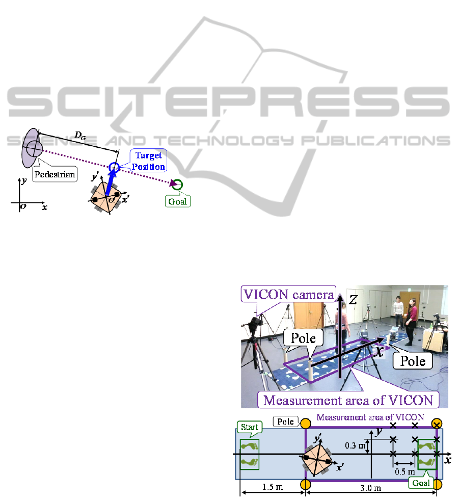
Figure 8: Design of the attractive potential to lead the
participant while maintaining a certain distance.
G
D
3.4 Navigation based on Artificial
Potential Method
In order to realize that the robot leads the participant
to the goal position, the velocity command is
determined based on the artificial potential method
(Khatib, 1986).
In the potential method, the potential field is
designed with an attractive potential field based on
the goal position and repulsive potential field based
on the obstacle position. Then, the robot determines
the motion based on the vertical force derived from
the potential field.
As shown in Figure 8, to lead the participant
while maintaining the certain distance
G
D
from the
participant, the target position of the robot is defined
as the position which is
G
D
distance to the goal
direction from the participant. Then, the attractive
potential is designed based on the target position. To
allow the participant to recognize the surrounding
environment by keeping their gaze in front, we set
1.5
G
D
. Determination of the velocity command
considering the velocity of the participant is future
work.
4 EXPERIMENT
To verify the accuracy of the foot contact times and
positions measured by the proposed gait
measurement robot, we carried out straight walking
test with five young people. The foot contact times
and positions measured by the proposed robot
compared with those measured by the three-
dimensional motion analysis system (VICON) with
six cameras. Figure 9 shows the field of the straight
walking test. As shown in Figure 10, the robot built
the environmental map in advance. The cell size was
set to 0.03 m. In addition, the field coordinate
system of the proposed system was fixed to that of
VICON by using poles shown in Figure 9.
As shown in Figure 11, VICON markers were
attached to the 18 places in the lower limbs of the
participant and Plug-In-Gait model was used for
motion analysis. In addition, for verification of the
trajectory of the legs, additional markers were
attached to each leg at the same height of the LRS.
Furthermore, for verification of the robot
localization, markers were attached to the front and
back of the robot shown in Figure 11. The true pose
of the robot was calculated using the two markers.
In this study, we define the foot contact time as
the foot bottom is attached to the floor and the leg is
perpendicular to the floor. From the VICON analysis,
Figure 9: Experimental field.
ICINCO2014-11thInternationalConferenceonInformaticsinControl,AutomationandRobotics
132
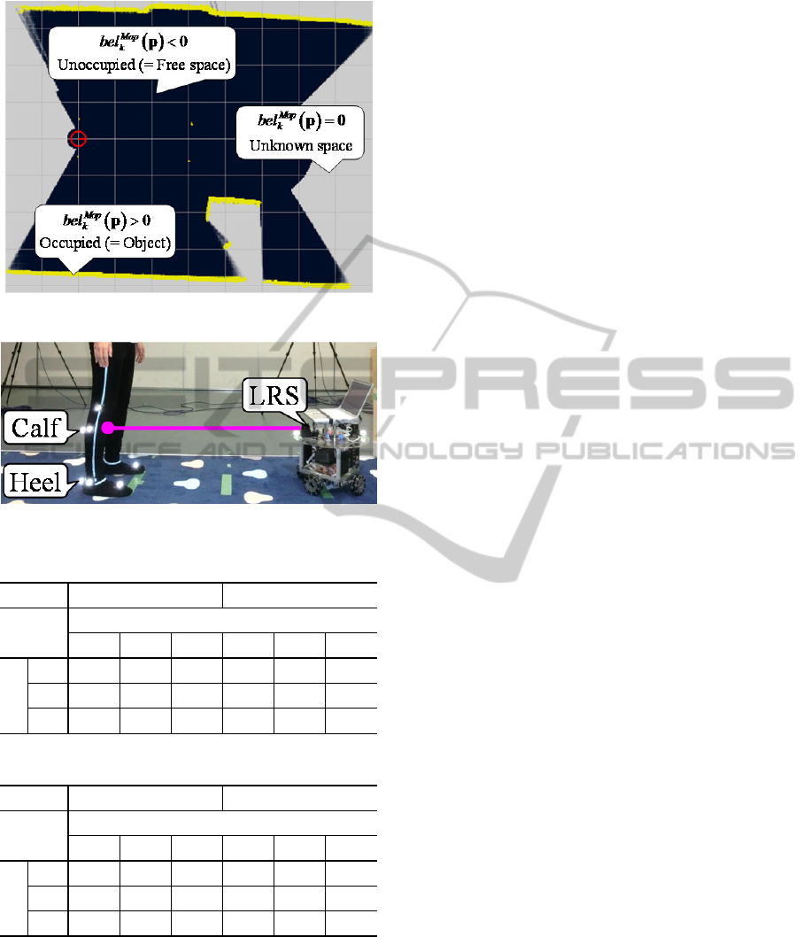
Figure 10: Map built by the robot in the experimental field.
Figure 11: Positions of the attached VICON markers.
Table 2: Acquired leg position error (x-coordinate).
Mean [m] SD [m]
Position
x
0.5 1.0 1.5 0.5 1.0 1.5
y
0.0 0.017 0.016 0.013 0.010 0.013 0.011
0.3 0.015 0.014 0.010 0.010 0.010 0.008
0.6 0.009 0.022 0.019 0.008 0.011 0.011
Table 3: Acquired Leg position error (y-coordinate).
Mean [m] SD [m]
Position
x
0.5 1.0 1.5 0.5 1.0 1.5
y
0.0 0.022 0.031 0.035 0.026 0.029 0.030
0.3 0.020 0.023 0.027 0.027 0.026 0.026
0.6 0.028 0.023 0.024 0.023 0.023 0.024
it was confirmed that the time when the marker of
the heel was not moving was almost equal to the
time when the leg was perpendicular to the floor.
Therefore, the true value of the foot contact time
was calculated as the time when the speed of the
heel marker was at a minimum. Then, the foot
contact position was acquired as the position of the
heel marker at that time. As shown in Figure 11,
since the measurement points of the robot were
different those of VICON, the positions of the legs
acquired by the robot were modified considering the
leg width of the participant to compare with the
VICON analysis.
4.1 Verification in Stationary State
We verified the accuracy of the localization and the
leg positions acquired by the robot in stationary state.
4.1.1 Localization
The robot stayed at nine points shown in Figure 9 as
a symbol “
”. The accuracy of localization for 5.0 s
in each point was verified. The maximum
localization errors of
x
-coordinate,
y
-coordinate and
yaw angle were respectively 0.070 m, 0.020 m and
0.030 rad. It was confirmed that the proposed robot
was able to estimate its own pose with high accuracy
equivalent to that of the measurement accuracy of
the LRS.
4.1.2 Leg Position
The robot stayed at the origin of the field and the
participant was standing at nine points shown in
Figure 9 as a symbol “
”. The accuracy of the
acquired leg position of each point for 5.0 s was
verified. Table 2 and 3 show the mean and the
standard deviation (SD) of the measurement error of
the right leg position acquired by the robot
compared with the heal position acquired by VICON
in each point. From the results in stationary state, it
was confirmed that the proposed robot could
measure the foot position with high accuracy
equivalent to that of the measurement accuracy of
the LRS.
4.2 Verification in Straight Walking
Test
We verified the accuracy of the localization and
acquired foot contact times and positions in straight
walking test.
4.2.1 Localization
Figure 12 show an example of the results of
localization in straight walking test. The mean of the
localization error of
x
-coordinate,
y
-coordinate and
yaw angle were respectively 0.043 m, 0.036 m and
0.020 rad. It was confirmed that the proposed robot
was able to estimate its own pose in moving state
with the same accuracy in stationary state.
DevelopmentofGaitMeasurementRobotforPreventionofFallsintheElderly
133
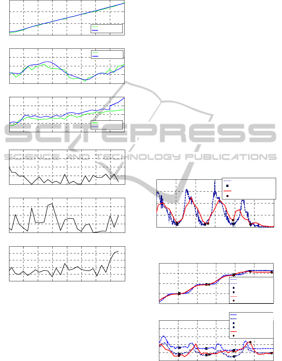
(a) Localization
(b) Localization error
Figure 12: An example of the results of localization in
straight walking test.
4.2.2 Foot Contact Time
Figure 13 shows the an example of the results of the
speed of the right leg acquired by the proposed robot
and the speed of the calf positions aquired by
VICON. The mean and SD of the error of the foot
contact time in five walking test were 0.147 s and
0.110 s. From the results, it was comfirmed that the
proposed robot could acquire the foot contact time
based on the estimated speed of the leg.
4.2.3 Foot Contact Position
Figure 14 shows an example the results of right leg
position and foot contact positions acqurired by the
proposed robot and the heel and calf positions
acquired by VICON. The total measurement error
mean and SD of the foot contact positions of
x-
coordinate were 0.035 m, 0.031 m and the those of
y-coordinate were 0.036 m, 0.023 m. From the
experimental results, it was comfirmed that the
proposed robot can acquire the foot contact positions
while leading the participant to the goal position of
the walking test field.
5 CONCLUSIONS
In this study, we proposed a novel gait measurement
system which uses an autonomous mobile robot with
laser range sensor (LRS) for a long-distance walking
test in a real living space regardless of detection
range of sensor. To realize smooth movement
depending on the movement of the participant, the
robot has an omnidirectional drive system and is
Figure 13: An example of the results of acquired leg speed
and foot contact time.
Figure 14: An example of the results of acquired right leg
position and foot contact position.
2 2.5 3 3.5 4 4.5 5 5.5 6
-1
0
1
2
time [s]
x
[m]
Robot
x
(LRF)
Robot
x
(VICON)
2 2.5 3 3.5 4 4.5 5 5.5 6
0
0.05
0.1
0.15
0.2
time [s]
y
[m]
Robot
y
(LRF)
Robot
y
(VICON)
2 2.5 3 3.5 4 4.5 5 5.5 6
-0.1
0
0.1
0.2
0.3
time [s]
[rad]
Robot
(LRF)
Robot
(VICON)
2 2.5 3 3.5 4 4.5 5 5.5 6
0
0.05
0.1
0.15
0.2
time [s]
Estimated error of
x
[m]
2 2.5 3 3.5 4 4.5 5 5.5 6
0
0.01
0.02
0.03
0.04
time [s]
Estimated error of
y
[m]
2 2.5 3 3.5 4 4.5 5 5.5 6
0
0.02
0.04
0.06
0.08
0.1
time [s]
Estimated error of
[rad]
2 3 4 5 6 7 8
0
0.5
1
1.5
2
time [s]
v
[m/s]
VICON (calf)
VICON foot contact (calf)
Robot
Robot foot contact
2 3 4 5 6 7 8
-2
-1
0
1
2
time [s]
x
[m]
2 3 4 5 6 7 8
-0.1
-0.05
0
0.05
0.1
time [s]
y
[m]
VICON (heel)
VICON (calf)
VICON foot contact (heel)
VICON foot contact (calf)
Robot
Robot foot contact
VICON (heel)
VICON (calf)
VICON foot contact (heel)
VICON foot contact (calf)
Robot
Robot foot contact
ICINCO2014-11thInternationalConferenceonInformaticsinControl,AutomationandRobotics
134

designed to be able to put out an average of human
walking speed. The robot sequentially estimates its
own pose and acquires both legs of the participant
based on the distance data from the sensors. The
robot leads the participant from the start to the goal
of the walking test while maintaining a certain
distance from the participant. Then, the foot contact
times and positions are calculated by analyzing
estimated position and speed of each leg.
To verify the accuracy of the foot contact times
and positions acquired by the proposed robot,
straight walking test with five young people were
carried out. From the experimental results compared
with a three-dimensional motion analysis system
(VICON), it was confirmed that the proposed robot
could acquire the foot contact times and positions.
Experiments with elderly people in living space
and verifications for the characteristic motion such
as cross step where the participant cross the
swinging leg against the supporting leg are future
work. In addition, velification of the robustness of
the localization of the robot in a real living space
and leg tracking is future work.
ACKNOWLEDGEMENTS
This work was supported by Grant-in-Aid for Japan
Society for the Promotion of Science (JSPS) Fellows
Grant Number 25-5707 and JSPS KAKENHI Grant
Number 25709015.
REFERENCES
Bellotto, N., Hu, H., 2009. Multisensor-Based Human
Detection and Tracking for Mobile Service Robots,
IEEE Transactions on Systems, Man and Cybernetics-
Part B: Cybernetics, Vol. 39, No. 1, pp. 167-181.
Davis, R., Õunpuu, S., Tyburski, D., Gage, J., 1991. A gait
analysis data collection and reduction technique,
Journal of Human Movement Scienc, Vol. 10, No. 5,
pp. 575-587.
HOKUYO AUTOMATIC CO, LTD., available from
<http://www.hokuyo-aut.jp/>, (accessed on 24 June,
2014).
Kakamigahara Health Promotion Power-up Business
“Lively Health Challenge 2007 spring”, available from
<http://www.waseda.jp/prj-
i4id/kakamigahara/project/event/070519/02.html>,
(accessed on 24 June, 2014), (in Japanese).
Kakinuma, K., Ozaki, M., Hashimoto, M., Yokoyama, T.,
Takahashi, K., 2011. Laser-Based Pedestrian Tracking
with Multiple Mobile Robots Using Outdoor SLAM,
IEEE International Conference on Robotics and
Biomimetics 2011, pp. 998-1003.
Khatib, O., 1986. Real-time Obstacle Avoidance for
Manipulators and Mobile Robots, International
Journal of Robotics Research, Vol. 5, No. 1, pp. 90-98.
Matsumura, T., Moriguchi, T., Yamada, M., Uemura, K.,
Nishiguchi, S., Aoyama, T., Takahashi, M., 2013.
Development of measurement system for task oriented
step tracking using laser range finder. Journal of
NeuroEngineering and Rehabilitation, Vol. 10, No. 47.
Melzer, I., Oddsson, L., 2004. The effect of a cognitive
task on voluntary step execution in healthy elderly and
young individuals, Journal of the American Geriatrics
Society, Vol. 52, pp. 1255-1262.
Melzer, I., Shtilman, I., Rosenblatt, N., Oddsson, L., 2007.
Reliability of voluntary step execution behavior under
single and dual task conditions, Journal of
NeuroEngineering and Rehabilitation, Vol. 4.
Ratsamee, P., Mae, Y., Ohara, K., Takubo, T., Arai, T.,
2012. People Tracking with Body Pose Estimation for
Human Path Prediction, IEEE International
Conference on Mechatronics and Automation 2012, pp.
1915-1920.
Schoene, D., Load, S.R., Delbaere, K., Severino, C.,
Davies, T.A., Smith, S.T., 2013. A Randomized
Controlled Pilot Study of Home-Based Step Training
in Older People Using Videogame Technology,
Journal of PLOS ONE, Vol. 8.
Shotton, J., Fitzgibbon, A., Cook, M., Sharp, T.,
Finocchino, M., Moore, R., Kipman, A., Blake, A.,
2011. Real-time Human Pose Recognition in Parts
from Single Depth Images, CVPR.
Tinetti, M.E., Speechley, M., Ginter, S.E., 1988. Risk
factors for falls among elderly persons living in the
community, New England Journal of Medicine, Vol.
319, pp.1701-1707.
Thrun, S., Burgard, W., Fox, D., 2005, Probabilistic
Robotics, MIT press.
World Health Organization, 2008. WHO Global Report on
Falls Prevention in Older Age, WHO press.
Yamada, M., Tanaka, B., Nagai, K., Aoyama, T., Ichihashi,
N., 2011. Rhythmic stepping exercise under cognitive
conditions improves fall risk factors in community-
dwelling older adults: Preliminary results of a cluster-
randomized controlled trial, Aging & mental health,
Vol. 15, pp.647-653.
Yamada, M., Higuchi, T., Mori, S., Uemura, K., Nagai, K.,
Aoyama, T., Ichihashi, N., 2012. Maladaptive turning
and gaze behavior induces impaired stepping on
multiple footfall targets during gait in older
individuals who are at high risk of falling, The
Archives of Gerontology and Geriatrics, Vol. 54, pp.
102-108.
Yamaura, K., Kamata, N., Taira, T., Yamasaki, N., 2005.
A Map Generation System by using Movable Infrared
Sensors for an Autonomous Mobile Robot,
ROBOMEC2005, (in Japanese).
Yorozu, A., Takahashi, M., 2014. Gait Measurement
System for the Elderly Using Laser Range Sensor,
Applied Mechanics and Materials, Vols. 490-491, pp.
1629-1635.
DevelopmentofGaitMeasurementRobotforPreventionofFallsintheElderly
135
