Multispectral Data Fusion for Robotic Reconnaissance and Mapping
Petra Kocmanova
1
, Ludek Zalud
2
, Frantisek Burian
2
and Tomas Jilek
2
1
Institute of Geodesy, Brno University of Technology, Veveri 331/95, Brno, Czech Republic
2
CEITEC, Brno University of Technology, Technicka 3082/12, Brno, Czech Republic
Keywords: Data Fusion, Sensory Head, Range Camera, CCD Camera, Thermal Imager.
Abstract: The aim of the paper is to describe the data-fusion from optical sensors for mobile robotics reconnaissance
and mapping. Data are acquired by stereo pair of CCD cameras, stereo pair of thermal imagers, and TOF
(time-of-flight) camera. The fusion is realized by means of spatial data from a TOF camera to ensure
”natural” representation of a robot’s environment; thus, the thermal and CCD camera data are comprised in
one stereo image presented to a binocular, head-mounted display. The data acquisition is performed using a
sensor head, which is placed on an Orpheus-X3 robot; both the head and the robot were developed by our
working group. After the geometrical calibration of each sensor, the positions of the sensors in 6DOFs are
computed. The corresponding data from the CCD camera and the thermal imager are subsequently
determined via homogeneous and perspective transformations. The result consists in an image containing
aligned data from the CCD camera and the thermal imager for each eye. TOF camera calibration and its
impact to the precision of fusion is described. Although the fusion is used for two different tasks –
automatic environment mapping and visual telepresence, the utilised calibration and fusion algorithms are,
in principle, the same.
1 INTRODUCTION
The described calibration and data-fusion algorithms
may be used for two purposes: visual telepresence
(remote control) under extremely wide variety of
visual conditions, like fog, smoke, darkness, etc.,
and for multispectral autonomous digital mapping of
the robot’s environment.
The method uses a combination of „classical“
cameras working in visible spectrum with thermal
imagers working in 7-14um spectrum. Each of them
has certain advantages and disadvantages.
Modern visible-spectrum cameras offer a very
good overview of the situation with high resolution.
Their image representation is the most intuitive for
the operator. On the other hand the dynamic range of
them is much lower than the one of a human eye.
They also do not work in complete darkness, cannot
see through fog or smoke.
Thermal imagers became widely available during
the last couple years, when their price was reduced
significantly. The main advantages - they can
percept in fog, at least for short distances, they are
also almost unaffected by visible light, so it does not
matter how the scene is illuminated (complete
darkness, point light sources, …). The main
disadvantages – they offer significantly lower pixel
resolution comparing to standard cameras, they are
still significantly more expensive and the image
offered is not so intuitive to the operator, since it
basically corresponds to temperatures of the objects.
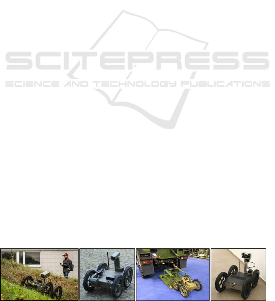
So it seems valuable to combine these two
Figure 1: Orpheus robots (from left) – Orpheus Hope, Oprheus-AC2, Orpheus-AC2, Orpheus-X3.
459
Kocmanova P., Zalud L., Burian F. and Jilek T..
Multispectral Data Fusion for Robotic Reconnaissance and Mapping.
DOI: 10.5220/0005060504590466
In Proceedings of the 11th International Conference on Informatics in Control, Automation and Robotics (ICINCO-2014), pages 459-466
ISBN: 978-989-758-040-6
Copyright
c
2014 SCITEPRESS (Science and Technology Publications, Lda.)

imagers into one image. Nowadays several
companies provide combined CCD – thermal
imagers, but their approach is simplistic – the
images are only geometrically aligned, so because of
parallax the images do not correspond exactly for
most cases. Furthermore the used CCD cameras are
typically of low quality and with limited field of
view. So these solutions are not appropriate for
telepresence in rescue robotics.
The technique was studied by our team in the
past (Zalud, 2005), but as the sensory prices
decreased and TOF cameras matured, the technique
now may be done more advanced. In this article we
introduce a technique for visual spectrum data and
thermal imager data alignment with help of data
from TOF camera. The TOF camera measures a
distance of an object, while corresponding pixels are
found on color camera and thermal imager. Each of
the sensors has to be calibrated for geometrical
errors, mutual position and orientation is found and
used to make the correspondence calibrations.
This is done for two stereo-pairs of cameras, so
the resulting image may be presented to head-
mounted display with stereovision support, so the
operator has a very good spatial representation of the
surrounding under any visibility conditions.
It has to be pointed out the sensors on the
sensory head will not be used only for this
technique, in parallel we also develop SLAM
technique with similar texture-mapping algorithms.
2 HARDWARE
2.1 Orpheus-X3
The Orpheus-X3 is an experimental reconnaissance
robot based on the Orpheus-AC2 model made by our
team to facilitate the measurement of chemical and
biological contamination or radioactivity for military
purposes (Fig. 1). The Orpheus-X3 offers the same
drive configuration as its predecessor, namely the
four extremely precise AC motors with harmonic
gears directly mechanically coupled to the wheels;
this configuration makes the robot very effective in
hard terrain and enables it to achieve the maximum
speed of 15 km/h. The main difference consists in
the chassis, which is not designed as completely
waterproof but consists of a series of aluminum
plates mounted on a steel frame of welded L-
profiles. This modular structural concept makes the
robot markedly more versatile, which is a very
important aspect in a robot made primarily for
research activities. Furthermore, the device is
equipped with a 3DOF manipulator for the sensory
head. The manipulator, again, comprises very
powerful AC motors combined with extremely
precise, low backlash harmonic drive gearboxes by
the Spinea company. The presence of such precise
gearboxes can be substantiated by several reasons,
mainly by the fact that the robot will be used not
only for telepresence but also for mobile mapping
and SLAM. As currently planned, the robot’s only
proximity sensor will be the TOF camera placed on
the sensory head.
Figure 2: The sensory head. 1 – the tricolor CCD cameras,
2 – the thermal imagers, 3 – the TOF camera.
2.1.1 Sensory Head
The sensory head containing five optical sensors is
shown in Fig. 2.
Two tricolor CCD cameras (see 1 in Fig. 2).
TheImagingSource DFK23G445 with 1280x960
pixels resolution, max refresh rate 30Hz, and
GiGe Ethernet protocol. A Computar 5mm 1:1.4
lens is used.
Two thermal Imagers (see 2 in Fig. 2).
MicroEpsilon TIM 450 with a wide lens,
382x288 pixels resolution, temperature resolution
of 0.08K, a USB output.
One TOF camera (see 3 in Fig. 2). A Mesa
Imaging SR4000 with the range of 10m, 176x144
pixels resolution, an Ethernet output. The field of
view is 56˚(h) x 69˚(v).
From the preceding text we can conclude, the
fields-of-view (FOVs) of the sensors are similar.
The largest FOV captures TOF camera, which is
required for simultaneous use of stereovision and
thermal stereovision. The main disadvantage of the
used TOF camera is its low number of pixels (spatial
resolution). In relation to the CCD cameras is about
10 times lower in one axis and in relation to thermal
imagers, it is 2 times lower.
1
1
2
2
3
ICINCO2014-11thInternationalConferenceonInformaticsinControl,AutomationandRobotics
460

3 SENSOR CALIBRATION
PROCEDURE
The reasons for the sensory head calibration are
following:
Simultaneous use of all five sensors leads to
necessity of determination translations and
rotations among cameras.
Absolute range precision guaranteed by the
manufacturer for range camera is ± 15 mm, but
only for the central 11 × 11 pixels. According to
our experience, range measurement is less precise
- for details see (Kocmanova, 2013)
Temperature shift in color-coded thermal images
(about 1.5K) must be resolved for simultaneous
use of 2 thermal imagers.
With respect to the previous description,
calibration of the sensory head consists of the
following parts (see Fig. 3): range calibration,
temperature calibration, calibration of intrinsic and
extrinsic parameters.
Figure 3: Calibration scheme for all sensors.
3.1 Range Calibration
Range calibration of the TOF camera is detailed
described in (Kocmanova, 2013). Improvement of
range accuracy is evident from Fig. 4. Range
accuracy was tested in 4 regions (see Fig. 5) that are
defined by manufacturer (SR4000, 2011).
3.2 Temperature Calibration
The microEpsilon TIM 450 low quality thermal
imagers were used for this application. The main
reason for this was the low price and very small
dimensions. Although the temperature resolution
(0.08K according to the datasheet) is relatively
sufficient, the absolute precision of 2K can be
defined as poor.
Figure 4: MSE of measured distance for all regions of
TOF camera before and after calibration.
Figure 5: Image division of TOF camera into the region by
accuracy.
In our application, we use two identical thermal
imagers for stereovision. The temperatures are
“expressed“ by colour-coding. In most cases, the
range of colors displayed is quite small (couple
of K). To provide the most relevant data to the
operator, it is important to use the narrowest
temperature range possible, because the more
different are the colors representing the nearby
temperatures, the better the visual perception is. But
as it was already mentioned, the temperature shift
between the two cameras may be - and indeed often
is during the first 30 minutes of operation - in the
order of Kelvins. This may cause unwanted color
shift between the left and right images (Fig. 6).
Figure 6: The temperature shift in the color-coded left and
right thermal images provided by the TIM450 cameras:
the calculated temperature shift is 1.5K. The grayscale
coding (upper row); the thermal-red coding (bottom row).
MultispectralDataFusionforRoboticReconnaissanceandMapping
461
The algorithm to solve this problem is as follows: A
temperature histogram of the left and right images is
made, and the cross-correlation (Eq. 1) function is
calculated. The maximum on the resulting function
corresponds to the actual mutual temperature shift
between the cameras, and therefore we then shift the
temperatures in one of the matrices.
hc
i
ikrhistilhistkcc
0
))(_*)(_()(
where hist_l and hist_r are the temperature discrete
histograms of the left or right thermal image
respectively, and hc is the histogram dimension.
3.3 Calibration of Intrinsic and
Extrinsic Parameters
An interesting problem was to find a material from
that a pattern would be clearly identifiable in the
images of all sensors. For opaque body, the sum of
surface reflectivity and emissivity equals to 1
(Bartl). To create a calibration plate it is necessary to
select two materials with significantly different
emissivity (i.e. also reflectivity). If the emissivity of
both materials isn´t sufficiently different, it is
possible to increase the contrast between materials
by heating one of them.
There are various options to find sufficiently
contract materials. In (Luhmann, 2010) authors
create plane test field that consists of wooden board
with 57 small lamps that warm up when switched on
and test field based on a metal surface with coded
and uncoded circle target points created using self-
adhesive foil. In (X.Ju, 2005) plane with heated
circle target was used for calibration of thermal
imager and color camera stereo pair, and in
(Prakash, 2006) a pair of thermal imagers was
calibrated with checker-board pattern heated by a
flood lamp.
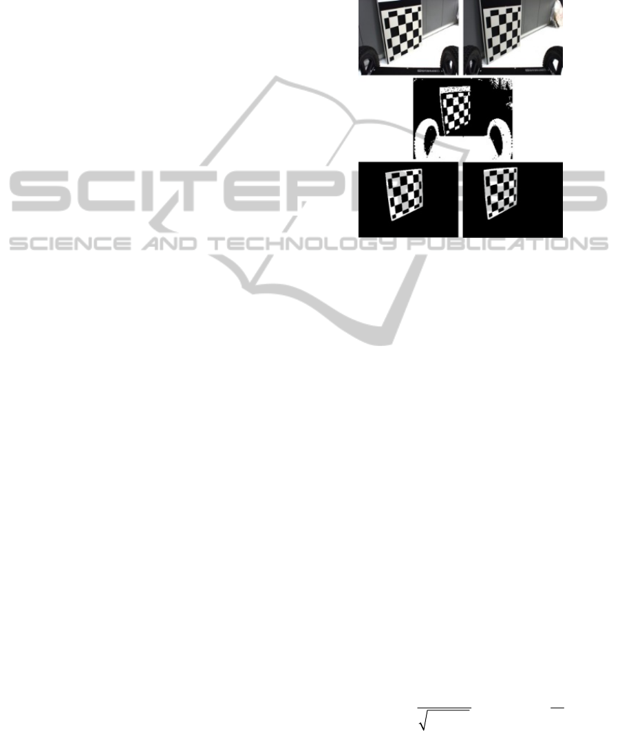
We proposed checkerboar calibration plate. First
version of calibration was from aluminum plate (low
emissivity, high reflectivity) and self-adhesive foil
(high emissivity, low reflectivity). This board had a
problem with high reflectivity of aluminum base.
Second version was aluminum plate with laser-
cut pattern coated by anodizing behind that was
aluminum plate chipboard covered by black matte
foil. Final version is 2mm thin laser-cut aluminum
plate with active heating (see Fig. 7)
Calibration of intrinsic and extrinsic parameters
is based on (Zhang, 1999) and is realized as follows:
the first step consisted in edge extraction, the second
was the initial calibration of intrinsic and extrinsic
parameters, and the last stage of the calculation
included nonlinear optimization (which minimizes
the sum of the squares of the re-projection errors
including the determination of distortion). The
mathematical model is detailed described in (Zalud,
2013, SSRR).
Figure 7: The calibration target: the left and right CCD
cameras (up), the TOF camera intensity image (center),
the left and right thermal imagers (down) camera.
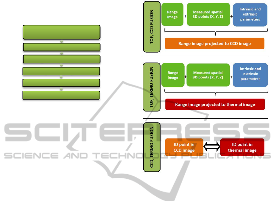
4 DATA FUSION PROCESS
Image transformations are applied for data fusion.
The range measurements of the TOF camera can be
displayed into images of CCD cameras and thermal
imagers using spatial coordinates. The procedure is
outlined in the diagram below (see Fig. 8). The input
data include the range measurement, the image
coordinates of all sensors, and the results of the
previous calibration.
The spatial coordinates X, Y, Z are computed
according to Eq. 2 and 3, where d is the measured
distance, x
c
, y
c
are the calibrated TOF image
coordinates, and f is the focal length of the TOF
camera. The homogeneous transformation is
determined by Eq. 4, where R
[3×3]
is the rotational
matrix, t
[3×1]
is the translation vector, and X', Y', Z'
are the spatial coordinates of the second sensor. The
image coordinates of the TOF camera in the next
frame x
c
',y
c
' are computed according to perspective
projection (see Eq. 5), where f' is the focal length of
the second sensor.
22
cos arctan cos arctan
cc
c
yx
Zd
f
fx
ICINCO2014-11thInternationalConferenceonInformaticsinControl,AutomationandRobotics
462
c
Zx
X
f
,
c
Zy
Y
f
Figure 8: Image transformation scheme.
1
10
1
'
'
'
Z
Y
X
tR
Z
Y
X
'
''
'
Z
Xf
x
c
'
''
'
Z
Yf
y
c
According to the identical (ID) points of the TOF
camera transformed into the frames of the CCD
camera and the thermal imager, the thermal image
can be displayed into the CCD image and vice versa.
The main objective of this paper is to calculate
and verify the accuracy of heterogeneous sensor data
fusion. We will focus on the weakest point of data
fusion i.e. range camera.
4.1 Influence of Distance Error on
Data Fusion Precision
The first investigated problem is influence of
objective point accuracy (or more precisely range
accuracy) on data fusion. Therefore, we determined
pixel differences caused by TOF camera radial
distance error for both CCD cameras and thermal
imagers. We simulated distance error for 2
significant image points: point on optical axis of the
TOF camera, point on the edge of the region 3 (see
Fig. 5) lying on the x-axis. Measured distances in the
region 4 have very low reliability, therefore this
region isn´t considered. The range of the radial
distance simulation is the same as detection range of
TOF camera i.e. 0.1 – 10.0 m.
The effect of distance error is not significant for
data fusion if transformed image coordinate
differences (CCD cameras and thermal imagers) not
exceed 0.5 pixel. For simulation we used values
Figure 9: Scheme of data fusion: up – TOF and CCD data
fusion; centre - TOF and thermal data fusion; down - CCD
and thermal data fusion.
based on distance error from range calibration. It is
also important to judge the usefulness and impact of
the range calibration. Distance error before
calibration 41 mm and after calibration 14 mm was
used for point on optical axis (reg. 1). Analogously
46 mm and 18 mm for point on the edge of reg. 3.
Figs. 10, 11 and Tab. 1 show effect of pixel error
in transformed images caused by distance error.
Graphs for point on the edge of reg. 3 have the same
character as Figs. 10 and 11. The numerical
difference is apparent from Tab. 1. For point on the
edge of reg. 3 are pixel error slightly higher than
point on optical axis (reg. 1). Distance error is
insignificant for radial distance greater than
approximately 2.5 m for CCD cameras before range
calibration and approximately 1.5 m for CCD
cameras after range calibration. Analogously to
thermal imagers, approximately 1.5 m before
calibration and 1 m after calibration.
Rangemeasurementandimage
coordinatesofTOFcamera
Spatial coordinates
Homogeneoustransformation
Perspectiveprojection
Correctionofprincipalpoint
Displayingoverlappingimages
MultispectralDataFusionforRoboticReconnaissanceandMapping
463

Figure 10: Image coordinate differences Δx caused by
distance error for point on optical axis of TOF camera.
Figure 11: Image coordinate differences Δy caused by
distance error for point on optical axis of TOF camera.
Table 1: Image Coordinate Differences 0.5 Pixel Cased By
Distance Error.
Distance
error
Image
coord.
Radial distance at that
pixel error causes by
distance error is 0.5 pixel
[m]
CCDl CCDr
TH.
l
TH.
r
Point
on
optical
axis
41 mm
before
calibration
x
2.43 2.49 1.30 1.34
y
2.40 2.40 – –
15 mm
after
calibration
x
1.48 1.51 0.79 0.81
y
1.45 1.45 – –
Point
on the
edge
of
reg. 3
46 mm
before
calibration
x
2.61 2.94 1.44 1.53
y
2.64 2.64 – –
18 mm
before
calibration
x
1.64 1.84 0.90 0.97
y
1.65 1.65 – –
Influence of low resolution of TOF camera is the
second investigated problem. The same 2 points and
same distance range as in previous section are used
for the simulation.
4.2 Influence of TOF Camera Low
Resolution on Data Fusion
Precision
Error 0.5 pixel in the image of TOF camera cause an
error of image coordinate x for CCD cameras
approximately 5 pixel (see Figs. 12, 14) and for
thermal imagers approximately 1.5 pixel (see Figs.
12, 14).
Figure 12: Image coordinate differences Δx caused by shift
of TOF image coordinate x of 0.5 pixel for point on optical
axis of TOF camera.
Figure 13: Image coordinate differences Δy caused by shift
of TOF image coordinate x of 0.5 pixel for point on optical
axis of TOF camera.
ICINCO2014-11thInternationalConferenceonInformaticsinControl,AutomationandRobotics
464
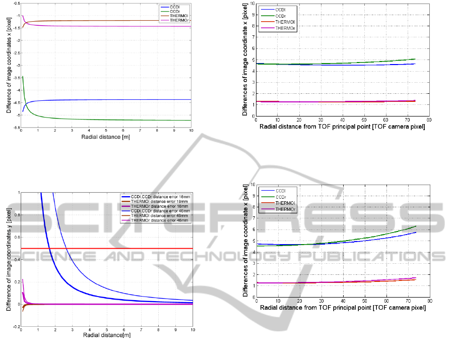
Figure 14: Image coordinate differences Δx caused by shift
of TOF image coordinate x of 0.5 pixel for point on the
edge of reg. 3.
Figure 15: Image coordinate differences Δy caused by shift
of TOF image coordinate x of 0.5 pixel for point on the
edge of reg. 3.
Error of image coordinate y is insignificant for
thermal imagers that are in the same height as TOF
camera and for CCD cameras only for points near
the optical axis of TOF camera (see Figs. 13 and
15). Influence of low resolution of TOF camera is
significant for points remote from optical axis (see
Fig. 13). Range calibration significantly improves
precision of CCD image coordinate y in this case
(see Fig. 15).
4.3 Influence of the TOF Image Radial
Distance on Data Fusion Precision
The third simulated effect was the influence of the
TOF camera image radial distance on data fusion
precision. The simulation comprised the error of 0.5
pixel in the TOF camera image coordinates and the
values of this error after the data fusion in images of
the CCD cameras and thermal imagers depending on
TOF image radial distance.
Figure 16: Image coordinate differences Δx caused by 0.5
TOF pixel error in dependence on the TOF image radial
distance.
Figure 17: Image coordinate differences Δy caused by 0.5
TOF pixel error in dependence on the TOF image radial
distance.
Different camera resolution values appear fully
in this simulation. The error of 0.5 pixel in the TOF
camera image causes, in the image coordinates x, y,
the error of approximately 5 pixels for the CCD
cameras and 1.5 pixels for the thermal imagers (see
Fig. 16, 17). Furthermore, the influence of low
resolution of the TOF camera slightly increases
depending on the TOF camera radial distance.
5 CONCLUSION AND FUTURE
WORK
Although the methods presented in this research
report are sufficiently applicable, stable, and reliable
(see Fig. 18), our research on the telepresence and
mapping subsystem of CASSANDRA is still far
from complete. The challenge we are currently
facing is to facilitate seamless combination of visual
telepresence and digital maps to form an augmented
reality system. The system should be able to add
map information to the “real-time” telepresence
MultispectralDataFusionforRoboticReconnaissanceandMapping
465

image so that the operator could see data such as the
temperatures through a robot that is not equipped
with a thermal imager; furthermore, it should also
facilitate the vision through or behind objects, and
perform other operations.
The CASSANDRA system is obviously also
intended to work outdoors, where other challenges
are waiting. We have already integrated a Velodyne
scanner as well as a high-precision RTK GNSS in
one of our robots, and thus we can build also
outdoor maps. We are currently working on several
supporting systems for outdoor telepresence.
Figure 18: Octree multispectral map of interior with data-
fusion.
ACKNOWLEDGEMENTS
This work was realised in CEITEC – Central
European Institute of Technology with research
infrastructure supported by the project
CZ.1.05/1.1.00/02.0068 financed from European
Regional Development Fund and by the Technology
Agency of the Czech Republic under the project
TE01020197 "Centre for Applied Cybernetics 3".
REFERENCES
P. Kocmanova and L. Zalud, “Spatial Calibration of TOF
Camera, Thermal Imager and CCD Camera”. In:
Mendel 2013: 19th International Conference on Soft
Computing. Brno: Brno University of Technology,
Fakulty of Mechanical Engineering, 2013, s. 343-348.
ISBN 978-80-214-4755-4.
SR4000 Data Sheet, MESA Imaging AG. Rev. 5.1, 2011.
J. Bartl and M. Baranek, “Emissivity of aluminium and its
importance for radiometric measurement”.
Measurement science review.
T. Luhmann, J. Ohm, J. Piechel and T. Roelfs, “Geometric
Calibration of Thermographic Cameras”. In:
International Archives of Photogrammetry, Remote
Sensing and Spatial Information Sciences 2010, vol.
XXXVIII, pp. 411-416.
X. Ju, J.-C. Nebel, J. P. Siebert, H. Gong, Y. Cai and J.-P.
Chatard,” 3D thermography imaging standardization
technique for inflammation diagnosis”. Proceedings of
the SPIE. 2005, vol. 5640, pp. 266-273.
S. Prakash, P. Y. Lee and T. Caelli,” 3D Mapping of
Surface Temperature Using Thermal Stereo”. 2006
9th International Conference on Control, Automation,
Robotics and Vision. IEEE, 2006, pp. 1-4.
Z. Zhang,”Flexible camera calibration by viewing a plane
from unknown orientations”. Proceedings of the
Seventh IEEE International Conference on Computer
Vision. IEEE, 1999, vol. 1, pp. 666-673.
L. Zalud and P. Kocmanova,”Fusion of Thermal Imaging
and CCD Camera-based Data for Stereovision Visual
Telepresence”.In: SSRR 2013: 11th IEEE
International Symposium on Safety Security and
Rescue Robotics, pp.1-6.
L. Zalud, F. Burian, L. Kopecny, P. Kocmanova (2013).
Remote Robotic Exploration of Contaminated and
Dangerous Areas, International Conference on
Military Technologies, pp 525-532, Brno, Czech
Republic, ISBN 978-80-7231-917-6.
L. Zalud, (2005). ORPHEUS – Reconniaissance
Teleoperated Robotic System. In: 16th IFAC World
Congress. pp. 1-6, Prague, Czech Republic.
D. Lichti, D.-Rouzaud: Surface-dependent 3D range
camera self-calibration. In: Proceedings of SPIE
Three-Dimensional Imaging Metrology, Vol. 7239,
2009, pp. 72390A-1-72390A-10.
ICINCO2014-11thInternationalConferenceonInformaticsinControl,AutomationandRobotics
466
