Hand-projector Self-calibration Using Structured Light
Christian S. Wieghardt and Bernardo Wagner
Institute for Systems Engineering, Real Time Systems Group
Leibniz Universit
¨
at Hannover, Appelstrae 9A, D-30167 Hannover, Germany
Keywords:
Self-calibration, Pattern Projection, Structured Light System, Motion Estimation.
Abstract:
This paper describes two methods for determining the extrinsic calibration parameters of a projector with
respect to the robot hand. One of them simultaneously solves the transformation between a camera with
respect to the robot base. Self-calibration means that no sort of calibration rig like a chessboard is needed.
Since the projector has no exteroceptive capabilities, a camera is placed in the environment or rigidly attached
to the robot base to detect the projected pattern. At different robot configurations correspondences between
the camera and projector are established to recover the transformation between them up to an unknown scale
factor. The common known formulations AX = XB and AX = ZB can be arranged in a linear form with
respect to the unknown extrinsic parameters and scale factors, and solved in least square sense.
1 INTRODUCTION
In robotics, a projector is typically used as an inter-
face or as a sensor in combination with at least one
camera. Recent developments have lead to a signif-
icant decrease in projector size, which facilitates the
usage in mobile applications. In our case, we are in-
terested in tracking the robot end-effector by means of
the projector. Because of the mobility we propose the
set-up shown in Figure 1. In order to apply a projector
appropriately on a robot hand, its homogeneous trans-
formation to the manipulator has to be determined.
This external calibration is addressed in this paper.
The main challenge is the restraint of calibration
rigs. They are not allowed by definition of self-
calibration. For calibration it is essential to move
the robot arm to different poses and capture the mo-
tions of the projector. But with no known objects
or constraints it is impossible to link the projector to
the environment. However, by detecting the relative
pose between the camera and the projector the hand-
projector transformation is still recoverable.
The projector can be described as the inverse of
the pinhole model - equal to most cameras. There-
fore we can identify the cameras and projectors intrin-
sic parameters with camera calibration based meth-
ods e.g. (Zhang, 2000). We assume that these
internal unknowns are determined beforehand with
one of the structured light system calibration meth-
ods, such as (Zhang and Huang, 2006) or (Moreno
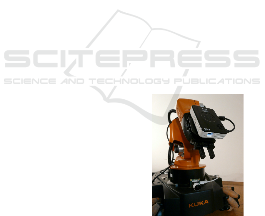
Figure 1: An LED pico projector AXAA P2 Jr mounted
on the KUKA youBots manipulator and a uEye camera
UI-1241LE-C-HQ on its platform.
and Taubin, 2012). The camera duality furthermore
enables the use of techniques known from existing
Hand-Eye-Calibrations. This problem was first ad-
dressed in (Shiu and Ahmad, 1989) and (Tsai and
Lenz, 1989). Later works considered simultaneous
robot-workspace calibration (Zhuang et al., 1994),
(Dornaika and Horaud, 1998), which allows the cali-
bration of an external camera. Of interest to our work
is (Andreff et al., 2001), where an unknown scale fac-
85
Wieghardt C. and Wagner B..
Hand-projector Self-calibration Using Structured Light.
DOI: 10.5220/0005065200850091
In Proceedings of the 11th International Conference on Informatics in Control, Automation and Robotics (ICINCO-2014), pages 85-91
ISBN: 978-989-758-039-0
Copyright
c
2014 SCITEPRESS (Science and Technology Publications, Lda.)

tor in the camera motion is incorporated.
So far, there are few publications with hand-
mounted projectors, that are usually calibrated only
to a second device on the robot arm. In (Reinhart
et al., 2007) a tracking system is used to manually
assign the projected points to world coordinates. Cal-
ibration was implemented with respect to the robot’s
tool flange. In (De Tommaso et al., 2012) the pro-
jector is calibrated to an rgb-d camera via homogra-
phies to planes observed by both devices. Calibration
to the end-effector was not concerned. Even though
no robot arm was applied, (Gavaghan et al., 2011)
utilized a projector to reference system calibration.
Markers were mounted on the device and on a cali-
bration plane to detect both movements with a stereo
camera. Extrinsic and intrinsic calibration was done
by projecting chessboard patterns on the plane and
identifying them with the stereo camera.
Notice that an additional camera mounted beside
the projector on the end-effector would result in a
structured light system. That second device would
ease the presented calibration, because the scale is
given by the baseline. But we argue the renounce-
ment of the camera with payload and space limita-
tions of the end-effector. The device is also not nec-
essary when tracking the robot hand by means of the
projector, on which we will focus in future research.
Therein we will increase the number of cameras to
obtain higher accuracy and robustness. So the re-
verse set-up, where the camera is mounted on the end-
effector and the projector placed e.g. at the robot base,
is not relevant for us.
The presented method eases the calibration proce-
dure since the calibration rig can be omitted. Thus, no
limitations are arising by the necessity of fully cover-
ing the rig by the projection during the determination
of good calibration robot arm poses. Furthermore,
all projector-camera correspondences can be used for
calibration.
The paper is organized as follows: In Section 2 it
is shown how to obtain the transformation between
the camera and the projector up to an unknown scale
factor. Those are needed for the calibration proce-
dure discussed in Section 3. We then present the ex-
perimental results in Section 4, and finally Section 5
offers a conclusion and an outlook to some future
works.
2 RELATIVE POSE ESTIMATION
This section introduces a procedure to establish the
relative pose between the camera and the projector.
Due to the unknown environment the translation can
only be recovered up the scale factor. This reduces
the homogeneous transformation between the camera
and the projector to a three-dimensional rotation and
a two-dimensional translation. As it is assumed that
the camera’s and projector’s intrinsic parameters are
known, five unknown parameters need to be deter-
mined.
2.1 Establishing Correspondences
First of all, correspondences between the projector
and the camera are established by projecting vertical
and horizontal fringe patterns onto the environment.
The sequence of patterns is coded to match the pro-
jector points x
p
= (x
p
,y
p
,1)
T
with the camera points
x
c
= (x
c
,y
c
,1)
T
. We use Gray coded patterns, as they
are easy to implement and allow for high density of
points (Salvi et al., 2004). The sequence of the Gray
code in one direction is shown in Figure 2 (a) and one
typical captured image of fringes consisting patterns
is given in Figure 2 (b).
(a) (b)
Figure 2: (a): Gray code, (b): One image of the Gray coded
image sequence.
The pattern is temporary coded, thus the robot
hand has to keep its pose during the image capturing.
The projector pixels x
p
are given by the Gray code.
However, to obtain the camera pixels x
c
, decoding has
to be done. For each image every pixel illumination
(on/off) is specified by comparison to a reference im-
age. The Gray code position is defined by the vertical
and horizontal sequence of illumination. The mean of
the covered pixels gives x
c
.
2.2 Determining the Rotation and the
Direction of Translation
The epipolar geometry describes the intrinsic projec-
tive geometry for two views. This is also applicable
for our camera/projector combination since the pro-
jector is modelled as an inverse camera. The epipo-
lar geometry depends only on the intrinsic parame-
ters and the relative pose, not on the environment’s
structure - an essential property for self-calibration.
The fundamental matrix F relates the image points to-
ICINCO2014-11thInternationalConferenceonInformaticsinControl,AutomationandRobotics
86

gether:
x
T
p
Fx
c
= 0. (1)
F can be transformed in a linear normalized form,
filled with all correspondences and it can be solved
in least square sense (Hartley, 1997). Notice that
even though the fundamental matrix encapsulates
the internal parameters, it can also be determined
without them. The essential matrix E will be re-
covered with the projector’s and camera’s intrinsic
matrices K
p
and K
c
:
E = K
T
p
FK
c
. (2)
The essential matrix E has five degrees of free-
dom, depends only on the pose between the camera
and the projector and can be also expressed by:
E = [t]
x
R, (3)
where [t]
x
is an antisymmetric matrix defined as
[t]
x
=
0 −t
z
t
y
t
z
0 −t
x
−t
y
t
x
0
. (4)
R and t can be recovered from E and t up to scale.
(Hartley and Zisserman, 2000) extract out of the sin-
gular value decomposition of E:
E = UΣV
T
(5)
the four solutions:
(R,t) = (UWV
T
,±u
3
),W =
0 ±1 0
∓1 0 0
0 0 1
, (6)
one for which all points appear in front of the devices.
The solution of (6) can be further refined via nonlinear
optimization methods. We minimize the reprojection
error:
argmin
R,t
∑
i
d(x
ci
,
ˆ
x
ci
)
2
+ d(x
pi
,
ˆ
x
pi
)
2
(7)
by means of the Levenberg-Marquardt algorithm, im-
plemented in (Lourakis, 2004).
3 CALIBRATION METHOD
In this Section we introduce two linear formulations
of the hand-projector calibration, one of which in-
cludes simultaneous robot-camera calibration. There-
fore we alter the hand-eye and robot-workspace cal-
ibrations to support our calibrations by taking the
unique scale factors for each pose into account. This
procedure follows (Andreff et al., 2001), who intro-
duces a linear formulation of the hand-eye calibra-
tion A
i
(λ)X = XB
i
for structure-from-motion meth-
ods, thus containing one scale factor.
3.1 Hand-projector
For hand-projector calibration we need to determine
X out of the common equation:
A
i
(λ
k
,λ
l
)X = XB
i
, (8)
which is supplemented with the unknown scale fac-
tors - see Figure 3. A
i
are the projectors and B
i
the
robot end-effectors movements. Movement i is de-
fined by transformation from pose k to l:
A
i
(λ
k
,λ
l
) = P
−1
k
(λ
k
)P
l
(λ
l
) (9)
= (R
T
ak
R
al
,R
T
ak
(λ
l
u
al
− λ
k
u
ak
)). (10)
Equation (8) can be split into a rotational and trans-
P
l
(λ
l
)
P
k
(λ
k
)
A
i
(λ
k
,λ
l
)
X
X
B
i
unknown environment
Figure 3: A projector is mounted on the end-effector and a
camera placed in the environment. For each movement i the
projected points change, involving different λs.
lational part:
R
ai
R
x
= R
x
R
bi
(11)
R
ai
t
x
+ R
T
ak
(λ
l
u
al
− λ
k
u
ak
)) = R
x
t
bi
+ t
x
. (12)
Using the vector operator:
vec(R) = (R
11
,...,R
1n
,R
2,1
,...,R
mn
), (13)
which rearranges matrices into vectors and its prop-
erty on matrix multiplications (Brewer, 1978):
vec(CDE) = (C ⊗ E
T
)vec(D). (14)
Equation (11) can be arranged in a linear form with
respect to the unknown paramters:
vec
R
ai
R
x
(R
bi
)
T
= vec (R
x
) (15)
(R
ai
⊗ R
bi
)vec(R
x
) = vec (R
x
) (16)
(R
ai
⊗ R
bi
)vec(R
x
) − I
9
vec(R
x
) = 0
9×1
. (17)
The same applies to the translational part (12):
I
3
⊗ t
T
bi
vec(R
x
) + t
x
− R
ai
t
x
(18)
−R
T
ak
(λ
l
u
al
− λ
k
u
ak
)) = 0
3×1
. (19)
Both parts result in the overall system:
I
9
− R
ai
⊗ R
bi
0
9×3
0
9×N
I
3
⊗ t
T
bi
I
3
− R
ai
−R
T
ak
U
ai
vec(R
x
)
t
x
Λ
= 0
12×1
(20)
Hand-projectorSelf-calibrationUsingStructuredLight
87

with the scale-free translation matrix and the corre-
sponding unknown scale factors:
U
ai
= u
al
e
l
− u
ak
e
k
, Λ = (λ
1
,...,λ
N
)
T
. (21)
3.2 Hand-projector and Camera-robot
Basis is the common equation:
A
i
(λ
i
)X = ZB
i
, (22)
which is supplemented with the unknown scale fac-
tors as well - see Figure 4. Here, A
i
are the
projector-camera and B
i
the robot end-effector poses.
Equation (22) can be split into a rotational and trans-
A
i
(λ
i
)
X
B
i
Z
unknown environment
Figure 4: A projector is mounted on the end-effector and a
camera is placed in the environment or attached to robot
platform. The camera optical frame coincides with the
world frame. For each pose i the projected points change,
resulting in a new λ
i
.
lational part:
R
ai
R
x
= R
z
R
bi
(23)
R
ai
t
x
+ λ
i
u
ai
= R
z
t
bi
+ t
z
. (24)
Using the vector operator and the property (Brewer,
1978) equation (23) can be arranged in a linear form
with respect to the unknown paramters:
(R
ai
⊗ R
bi
)vec(R
x
) − I
9
vec(R
z
) = 0
9×1
. (25)
The same applies to the translational part (24):
I
3
⊗ t
T
bi
vec(R
z
) + t
z
− R
ai
t
x
− λ
i
u
ai
= 0
3×1
. (26)
Both parts result in the overall system:
R
ai
⊗ R
bi
−I
9
0
9×3
0
9×3
0
9×N
0
3×9
I
3
⊗ t
T
bi
−R
ai
I
3
−U
ai
vec(R
x
)
vec(R
z
)
t
x
t
z
Λ
= 0
12×1
(27)
with the scale-free translation matrix and the corre-
sponding unknown scale factors:
U
i
= u
ai
e
i
, Λ = (λ
1
,...,λ
N
)
T
. (28)
3.3 Formulations with Known Scale
Here we give the final single linear systems to avoid
duplicity. Following previous sections, the formula-
tions are straightforward to get. With fully known t
ai
(20) reduces to:
I
9
− R
ai
⊗ R
bi
0
9×3
I
3
⊗ t
T
bi
I
3
− R
ai
vec(R
x
)
t
x
=
0
9×1
t
ai
. (29)
and (27) reduces to:
R
ai
⊗ R
bi
−I
9
0
9×3
0
9×3
0
3×9
I
3
⊗ t
T
bi
−R
ai
I
3
vec(R
x
)
vec(R
z
)
t
x
t
z
=
0
9×1
t
ai
.
(30)
3.4 Solvability
From (20) we see, that we have 12 + i unknowns and
can solve for 12i. In (27) we have 24 + i unknowns
and can also solve for 12i. Thus, at least three robot
arm poses have to be approached in both methods to
solve the homogeneous systems. Furthermore, we
notice from (Tsai and Lenz, 1989) that at least two
movements with nonparallel rotational axes are nec-
essary to get a unique solution of the hand-eye cali-
bration. This also applies for the cases with known
scale (29) and (30).
The homogeneous systems (20) and (27) are lin-
ear in the parameters and can be solved in least square
sense. Optionally, one can separately estimate the ro-
tational parameters R
x
and R
z
of the upper part and
afterwards the translational parameters t
x
, t
z
and Λ of
the lower part. Separating is reasonable having good
rotational data. Otherwise the error would propagate
into the translational data.
4 EXPERIMENTAL RESULTS
In this section the performances of both proposed
self-calibration formulations are presented. Further
comparison is given by their linear calibration equiv-
alent without any scale factors. All methods were car-
ried out in simulation and with real hardware.
Simulations validate the algorithm based on
ground truths and show the effect resulting from noisy
transformation data of the robot arm and the camera-
projector pair. Due to the increase of unknown pa-
rameters by one for each pose, less accurate results
are to be expected. This influence of the parameter
growth will also be shown in simulation by means of
their equivalents.
Since the physical robot arm and camera data
is strongly noisy, we also give a comparison to the
ICINCO2014-11thInternationalConferenceonInformaticsinControl,AutomationandRobotics
88
equivalents with the help of a chessboard. This out-
lines the achievable accuracy.
For evaluation, we used 135 different robot arm
configurations. The poses for computation were ran-
domly selected in a clustered manner to enlarge trans-
lation and rotation between the poses. We calculated
the rotational error e
R
of the estimated
ˆ
R by recov-
ering its rotation vector and determine the angle be-
tween its ground truth R
gt
, so that 0 ≤ e
R
≤ π is ful-
filled. The average transformations given by:
¯
t =
N
∑
i=1
||t
ai
|| + ||t
bi
||
2n
. (31)
Thus, the relative error results in e
t
= ||
ˆ
t − t
gt
||/
¯
t. We
took all possible movements between the poses into
account, leading to (N − 1)N/2 homogeneous trans-
formations. All four applied formulations are listed in
Table 1 and referenced in the following by their num-
ber.
Table 1: Applied Methods.
#1 Hand-Projector
A
i
(λ
k
,λ
l
)XXB
i
#2 Hand-Projector and Camera-Robot
A
i
(λ
i
)XZB
i
#3 Hand-Projector, known scale
A
i
XXB
i
#4 Hand-Projector and Camera-Robot, known scale
A
i
XZB
i
4.1 Synthesized Data
For our simulation, the robot arm poses B
i
are uni-
formly placed on a circle and alternately rotated
around two distinguished axes at each position. This
arrangement is based on the later used manipula-
tor’s workspace. With known X and Z the projector-
camera transformation is given by:
A
i
= ZB
i
X
−1
. (32)
We considered two sources of error: Noise in
translation and noise in rotation. Both are applied to
the robot arm poses and the camera-projector trans-
formations. For translation and rotation distribution
we randomly generated unit vectors with zero mean.
Either of them were multiplied by their corresponding
Gaussian distributed standard deviation σ
R
and σ
t
.
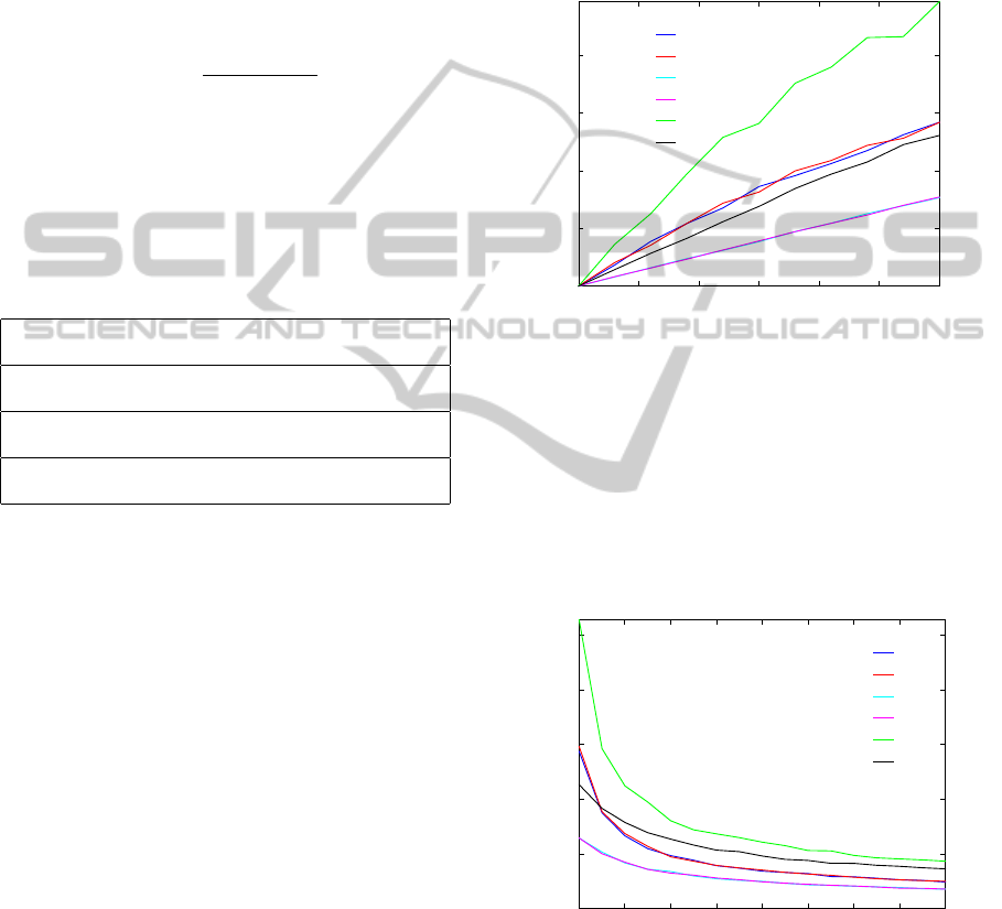
First, we show the dependency of transformation
perturbation in Figure 5 for N = 4 poses. A good cri-
terium is given by the relative position error of X,
since it is calculated for all four methods. By compar-
ing ¯e(t
x
#1−4
) we can conclude, that the most robust so-
lutions against translational error are #3 and #4, even
though #4 determines twice as many parameters as
#3. Whereas, incorporating the unknown scale fac-
tors Λ lead to a noticeable increase of errors in #1 and
#2. Thus, at no expense of accuracy in X one can ad-
ditionally solve for the camera pose Z. The errors of
X and Z depend on the set-up and the used manip-
ulator configurations, therefore usually deviate from
each other.
¯e
t
¯e(t
x
#1
)
¯e(t
x
#2
)
¯e(t
x
#3
)
¯e(t
x
#4
)
¯e(t
z
#2
)
¯e(t
z
#4
)
σ
t
0
0.05
0.1
0.15
0.2
0 0.005 0.01 0.015 0.02 0.025 0.03
Figure 5: Average relative error of t
x
and t
z
.
In Figure 6 we depicted the average relative error
for different numbers of poses. We deviated the cam-
era and robot arm poses with σ
t
= 0.01. It is shown,
that even for a high number of used poses, a gap be-
tween the solutions #1 ↔ #3 and #2 ↔ #4 remains
due to the unknown scale factors. Again, the com-
parison of #1 ↔ #2 and #3 ↔ #4 reveals that solving
for the unknown Z does not effect the accuracy.
¯e
t
¯e(t
x
#1
)
¯e(t
x
#2
)
¯e(t
x
#3
)
¯e(t
x
#4
)
¯e(t
z
#2
)
¯e(t
z
#4
)
Number Poses N
0
0.02
0.04
0.06
0.08
0.1
4 6 8 10 12 14 16 18 20
Figure 6: Average relative error of t
x
and t
z
at σ
t
= 0.01.
The dependency of rotation perturbation in shown
Figure 7 for N = 4 poses. It can bee clearly seen that
the rotation uncertainty has almost the same influence
on all methods. That is due to the high weighted ro-
tational parts of the linear systems. Since the upper
parts of systems (20) resp. (27) coincide with (29)
Hand-projectorSelf-calibrationUsingStructuredLight
89
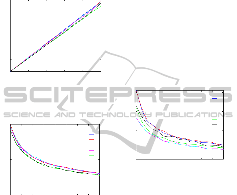
resp. (30) the average rotational errors are mostly de-
pendent of R
ai
and R
bi
.
¯e
R
¯e(R
x
#1
)
¯e(R
x
#2
)
¯e(R
x
#3
)
¯e(R
x
#4
)
¯e(R
z
#2
)
¯e(R
z
#4
)
σ
R
0
0.1
0.2
0.3
0.4
0.5
0 0.2 0.4 0.6 0.8 1
Figure 7: Average rotational error of R
x
and R
z
.
In Figure 8 we depicted the average relative error
for different numbers of poses. We deviated the cam-
era and robot arm poses with σ
R
= 1.0
◦
. As assumed,
the congruence continues at more applied poses.
¯e
R
¯e(R
x
#1
)
¯e(R
x
#2
)
¯e(R
x
#3
)
¯e(R
x
#4
)
¯e(R
z
#2
)
¯e(R
z
#4
)
Number Poses N
0
0.1
0.2
0.3
0.4
0.5
0.6
4 6 8 10 12 14 16 18 20
Figure 8: Average rotational error of R
x
and R
z
at σ
R
=
1.0
◦
.
4.2 Real Data
The experimental set-up is shown in Figure 1. The
KUKA youBot articulated robot arm consists of five
serial rotary joints. Due to the robot arm kinematic,
the end-effector poses are limited to those planes with
the axis of the first joint as a common line. The LED
pico projector AXAA P2 Jr at the end-effector has
a resolution of 1920x1080 pixels. The uEye cam-
era UI-1241LE-C-HQ from IDS has a resolution of
1280x1024 pixels. The presented hand-projector con-
figuration is convenient since the projector is pointed
at the workspace. For full calibration, two distinct ro-
tations between the poses are necessary. This can be-
come a difficult task, because the projector has to be
pointed to the same workspace in all poses. A good
rotation axis is given by the last joint since the pro-
jector’s view is just slightly changing. The second
rotation is given by the second to fourth joints. As
no ground truth is given, we select n = 1000 sets of
N = 20 poses and take the average solution.
To show the ability of self-calibration, the meth-
ods #1 and #2 were applied in an unknown environ-
ment with few desktop items - see Figure 2 (b). For
methods #3 and #4 we established the projectors mo-
tion by means of a chessboard, placed in the envi-
ronment. Local homographies are used to determine
the homogeneous transformation between the projec-
tor and the camera to the chessboard (Moreno and
Taubin, 2012). The results are given in Figure 9 and
Figure 10.
¯e
t
¯e(t
x
#1
)
¯e(t
x
#2
)
¯e(t
x
#3
)
¯e(t
x
#4
)
¯e(t
z
#2
)
¯e(t
z
#4
)
Number Poses N
0
0.01
0.02
0.03
0.04
0.05
0.06
0.07
4 6 8 10 12 14 16 18 20
Figure 9: Average relative error of t
x
and t
z
over the number
of poses N.
As already shown with help of the synthesized
data, the errors of X through #1 and #2 respectively #3
and #4 coincide. Notice that in the simulation we used
the transformations X and Z determined from the real
data. The main difference is the restricted workspace
of the manipulator. With these changed manipula-
tor configurations the resulting relation of accuracies
shifts. Compared with Z, the error of X increases in
position and decreases in orientation. The effect ap-
pears in a different amount for the methods, since #1
and #2 used slightly different configurations than #3
and #4.
In this experiment, we emphasized the achiev-
able accuracy of the applied hardware. Even though
the solutions converge well compared to their move-
ments, some errors remain. Unfortunately, the biggest
source of noise can not be assigned.
As assumed, the use of chessboard gives more
accurate results, since full pose data has been used.
Figure 10 confirms the good rotational data, follow-
ing the procedure of Section 2.
ICINCO2014-11thInternationalConferenceonInformaticsinControl,AutomationandRobotics
90
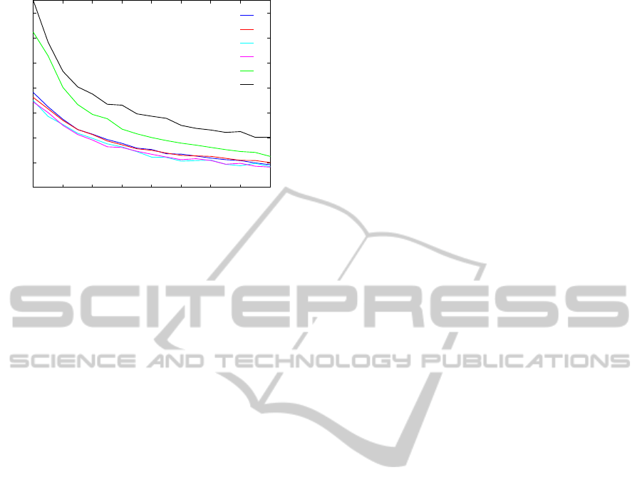
¯e
R
¯e(R
x
#1
)
¯e(R
x
#2
)
¯e(R
x
#3
)
¯e(R
x
#4
)
¯e(R
z
#2
)
¯e(R
z
#4
)
Number Poses N
0
0.05
0.1
0.15
0.2
0.25
0.3
0.35
4 6 8 10 12 14 16 18 20
Figure 10: Average rotational error of R
x
and R
z
over the
number of poses N.
5 CONCLUSIONS
This paper presents two self-calibration methods for
externally calibrating a projector to a robotic hand.
One of them additionally gives the solution of the
transformation between the robot base and an exter-
nal camera.
In contrast to existing approaches, the presented
solutions need neither any additional device at the
end-effector nor any calibration unit in the environ-
ment. The capability is demonstrated by the posi-
tive results of using real hardware. Provided with
ground truth data, simulations prove the accuracy of
the methods.
It has been shown that the error that results from
the unknown scale factors quickly converges by in-
creasing the number of poses. The additional error
resulting from simultaneously estimating the camera
pose is negligible. This is beneficial since the camera-
projector pair can be used as a structured light sensor.
Future works will tackle optimizing of the solu-
tion and identifying good robot arm poses for calibra-
tion. Spatial coded light will be considered, as it en-
ables us to use the method in dynamic environments.
REFERENCES
Andreff, N., Horaud, R., and Espiau, B. (2001). Robot
hand-eye calibration using structure-from-motion. In-
ternational Journal of Robotics Research, 20(3):228–
248.
Brewer, J. W. (1978). Kronecker products and matrix calcu-
lus in system theory. IEEE Trans Circuits Syst, CAS-
25(9):772–781.
De Tommaso, D., Calinon, S., and Caldwell, D. (2012).
Using compliant robots as projective interfaces in dy-
namic environments. Lecture Notes in Computer Sci-
ence, 7621:338–347.
Dornaika, F. and Horaud, R. (1998). Simultaneous robot-
world and hand-eye calibration. IEEE Transactions
on Robotics and Automation, 14(4):617–622.
Gavaghan, K., Peterhans, M., Oliveira-Santos, T., and
Weber, S. (2011). A portable image overlay
projection device for computer-aided open liver
surgery. IEEE Transactions on Biomedical Engineer-
ing, 58(6):1855–1864.
Hartley, R. (1997). In defense of the eight-point algorithm.
IEEE Transactions on Pattern Analysis and Machine
Intelligence, 19(6):580–593.
Hartley, R. and Zisserman, A. (2000). Multiple View Geom-
etry in Computer Vision.
Lourakis, M. (Jul. 2004). levmar: Levenberg-marquardt
nonlinear least squares algorithms in C/C++. [web
page] http://www.ics.forth.gr/∼lourakis/levmar/. [Ac-
cessed on 31 Jan. 2005.].
Moreno, D. and Taubin, G. (2012). Simple, accurate, and
robust projector-camera calibration. In 3D Imaging,
Modeling, Processing, Visualization and Transmis-
sion (3DIMPVT), 2012 Second International Confer-
ence on, pages 464–471.
Reinhart, G., Vogl, W., and Kresse, I. (2007). A projection-
based user interface for industrial robots. In Proceed-
ings of the 2007 IEEE International Conference on
Virtual Environments, Human-Computer Interfaces,
and Measurement Systems, VECIMS 2007, pages 67–
71.
Salvi, J., Pags, J., and Batlle, J. (2004). Pattern codification
strategies in structured light systems. Pattern Recog-
nition, 37(4):827–849.
Shiu, Y. C. and Ahmad, S. (1989). Calibration of wrist-
mounted robotic sensors by solving homogeneous
transform equations of the form ax = xb. IEEE Trans-
actions on Robotics and Automation, 5(1):16–29.
Tsai, R. Y. and Lenz, R. K. (1989). New technique for fully
autonomous and efficient 3d robotics hand/eye cali-
bration. IEEE Transactions on Robotics and Automa-
tion, 5(3):345–358.
Zhang, S. and Huang, P. (2006). Novel method for struc-
tured light system calibration. Optical Engineering,
45(8).
Zhang, Z. (2000). A flexible new technique for camera cal-
ibration. IEEE Transactions on Pattern Analysis and
Machine Intelligence, 22(11):1330–1334.
Zhuang, H., Roth, Z. S., and Sudhakar, R. (1994). Si-
multaneous robot/world and tool/flange calibration
by solving homogeneous transformation equations of
the form ax=yb. IEEE T. Robotics and Automation,
10(4):549–554.
Hand-projectorSelf-calibrationUsingStructuredLight
91
