
Reconfigurable CAN in Real-time Embedded Platforms
Imen Khemaissia
1,2
, Olfa Mosbahi
3
and Mohamed Khalgui
3
1
Cynapsys Company, France-Germany
2
Faculty of Sciences, Tunis El-Manar University, Tunis, Tunisia
3
National Institute of Applied Sciences and Technology, INSAT, University of Carthage, Tunis, Tunisia
Keywords:
Microcontroller, Networked STM32F4, CAN, Multi-agent-Architecture, Reconfiguration, Real-time, Frame-
packing.
Abstract:
This paper
1
deals with the dynamic reconfiguration of the frame packing as well as the traffic of real-time
packets on a CAN network. This network is assumed to link distributed reconfigurable STM32F4 microcon-
trollers that can automatically add-remove-update periodic and aperiodic OS tasks at run-time. These tasks
may exchange messages to be loaded in packets and to be sent on the network. After the addition of a pair
of dependent tasks on two microcontrollers, a message should be added on CAN and should respect a corre-
sponding deadline related to these tasks. After several additions of messages, some deadlines may be violated
and the CAN may not support the added messages. In addition, the frame packing should be adapted at
run-time to any reconfiguration scenario in the different microcontrollers. We propose a multi-agent based ar-
chitecture to check the correct transmission of messages. If some deadlines are violated, these agents propose
technical solutions for the feasibility of the whole system. They can suggest first the modification of periods
or deadlines of tasks and messages. They can propose also the removal of some OS tasks or messages from
the controllers according to their priorities. We propose in addition new solutions to construct the dynamic
frame-packing while the bandwidth is minimized. A tool is developed at LISI and Cynapsys to support the
different contributions of this paper.
1 INTRODUCTION
Nowadays, the most modern vehicles in the world use
Controller Area Networks (e.g. CAN)(Gmbh, 1991)
(K. Tindell and Wellings, 2000) to link their dis-
tributed embedded microcontrollers that allow more
functionalities and services (L. Chaari and Kamoun,
2002) (Marino and Schmalzel, 2007) (X. Wang and
Ding, 1999). These microcontrollersare implemented
by periodic and aperiodic tasks (Liu and Layland,
1973) (I. khemaissia and Bouzayen, 2014) that can
exchange messages on the network. The messages
are generally loaded in packets according to several
solutions such as the frame packing (Navet, 1998)
(R.S Marquos and Simon-Lion, 1998) (R. S. Mar-
ques, 2005) (K. Sandstrom and Ahlmark, 2000).
These tasks and consequently their messages should
1
This work is a collaboration between LISI Lab at Uni-
versity of Carthage in Tunisia and Cynapsys Company in
France-Germany. We thank the Cynapsys Directors Hei-
them Tebourbi and Souhail Kchaou for the fruitful and rich
discussions with them.
meet functional and temporal properties to be de-
scribed in user requirements. Moreover, these micro-
controllers should be flexible in some situations ac-
cording to the environment evolution and also user
requirements. A reconfiguration scenario is assumed
to be any run-time operation that adapts the system’s
behavior in each microcontroller and also on the net-
work (I. khemaissia and Bouzayen, 2014). A micro-
controller reconfiguration is assumed in the current
paper to be any automatic operation allowing the ad-
dition, removal or update of OS tasks that support the
system’s functionalities. A CAN reconfiguration is
assumed to be any addition, removal or updates of
messages that link dependent tasks on different mi-
crocontrollers. The problem that we want to resolve
today: how can we apply feasible reconfiguration sce-
narios that guarantee the respect of all deadlines es-
pecially for critical tasks ? how can we apply re-
configuration scenarios such that the system runs nor-
mally without any disturbance ? how can we adapt the
frame packing at run-time to load in packets new mes-
sages from new added tasks, or remove from packets
355
Khemaissia I., Mosbahi O. and Khalgui M..
Reconfigurable CAN in Real-time Embedded Platforms.
DOI: 10.5220/0005068103550362
In Proceedings of the 11th International Conference on Informatics in Control, Automation and Robotics (ICINCO-2014), pages 355-362
ISBN: 978-989-758-039-0
Copyright
c
2014 SCITEPRESS (Science and Technology Publications, Lda.)

old messages to be exchanged between old removed
tasks after a particular reconfiguration. In this pa-
per, we assume a system to be composed of n micro-
controllers which are linked by CAN. A multi-agent
architecture following the master/slave model is de-
fined to control the feasibility in the whole system
after the addition of messages. For that, three types
of agents are defined: 1) A master Agent Ag
CAN
: is
proposed to check the feasibility in CAN 2) A main
slave agent Ag
i
: is controlled by Ag
CAN
and defined
for each microcontroller to verify the feasibility of
its OS tasks after any reconfiguration scenario and
3) A second slave agent: Ag
frame
: its role is to de-
fine the new messages to be loaded in packets after
any reconfiguration scenario. A protocol communi-
cation between these agents is described. If a recon-
figuration scenario is required by a particular main
slave Ag
i
(i ∈ [1, n]) in the corresponding microcon-
troller and if this scenario affects the traffic of the
network (e.g. adds-removes or modifies the packets
on the network), then Ag
CAN
should be notified in or-
der to coordinate with the rest of microcontrollers. If
all the concerned microcontrollers accept this require-
ment, Ag
CAN
gets from them an acceptation signal
before authorizing Ag
i
to effectively apply this sce-
nario. In this case, the slave agent Ag
frame
should
adapt the frame packing to this scenario by removing
from CAN the old messages which are sent from old
tasks to be removed,and adding to CAN the new mes-
sages of the new added tasks. To guarantee a feasible
distributed system after any reconfiguration scenario,
we propose new technical solutions that can modify
the parameters of tasks such as deadlines, periods, ac-
tivation/deactivation of microcontrollers. Moreover,
we propose a new strategy to solve the problem of dy-
namic frame-packing by developing a new algorithm.
We suggest the bin-packing to locate the messages
into the different frames. These solutions are dealing
with the reconfiguration of microcontrollers and also
CAN are applied of three hierarchical levels: 1) Tasks
Level: the main slave agent Ag
i=1..n
in each micro-
controller verifies the feasibility of the whole system,
i.e, the utilization of each microcontrollermust be less
than/equal to 1, 2) CAN Bus Level: Ag
CAN
controls
the real-time constraints of the exchanged messages,
i.e, the bus utilization must be less than/equal to 1 and
3) Middleware Level: the second slave agent Ag
frame
constructs the dynamic frame packing with the mini-
mization of the bandwidth. The didactics multiplexed
vehicle of the INSAT institute is selected as a case
study throughout this paper and a tool is developed
at LISI laboratory in order to support the different
proposed solutions. The remainder of the paper is
as follows. Section 2 exposes some related works.
The case study is described in Section 3. Section 4
presents the multi-agent architecture which is imple-
mented and simulated in Section 5. We finish by a
conclusion in Section 6.
2 BACKGROUND
This section introduces some basic terms and con-
cepts which are used throughout this paper.
2.1 Real-time Characteristics
A real-time system can be composed of periodic, ape-
riodic and sporadic tasks. In this research, we are just
interested in periodic and/or aperiodic tasks. Each
periodic task is characterized by (Liu and Layland,
1973): (1) A release time R : It is the time when a
job becomes available for execution. We assume that
the tasks are synchronous, i.e, R = 0, (2) period T:
is the regular inter−arrival time, (3) deadline D: the
absolute deadline is equal to the release time plus the
relative deadline, (4) WCET C: is the time needed to
compute a job. and (5) static priority S: The highest
static priority which is equal to 1, i.e., S
i
= 1 repre-
sents τ
i
with the highest static priority. For aperiodic
tasks, we denote by d, WCETs c and r the deadlines,
the worst case execution times and the release times,
respectively. The aperiodic tasks arrive according to
the poisson distribution with the parameter λ
C
and
are executed according to the exponential distribu-
tion with the parameter λ
r
(I. khemaissia and Bouza-
yen, 2014). The aperiodic tasks can be with soft/hard
deadlines, i.e, the missing of the soft deadlines is ac-
ceptable and it is not the case for the hard deadlines.
According to (I. khemaissia and Bouzayen, 2014), the
microcontroller utilization U
bef
before a particular re-
configuration is calculated as follows:
U
bef
= U
per
+U
ape
(1)
Where:
• The microcontroller utilization of periodic tasks
U
per
=
n
∑
i=1
m
∑
j=1
C
i, j
T
i, j
. n and m represent the number
of the microcontrollers and the tasks respectively,
• The microcontroller utilization of aperiodic tasks
U
ape
=
n
∑
i=1
λ
ri
λ
Ci
.
We assume that the aperiodic tasks arrive with the
same rates in all the microcontrollers. To guarantee
the feasibility of the system before any reconfigura-
tion scenario, the followingcondition must be verified
for each microcontroller (Liu and Layland, 1973):
U
bef
≤ 1 (2)
ICINCO2014-11thInternationalConferenceonInformaticsinControl,AutomationandRobotics
356
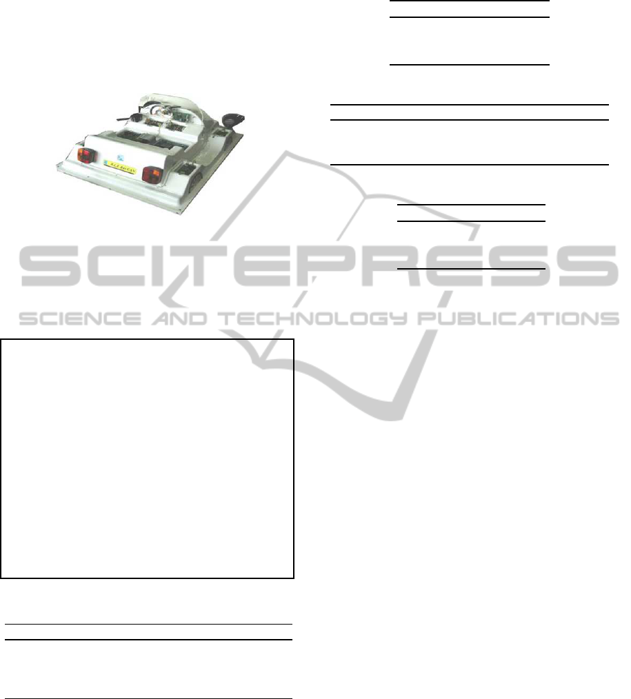
3 CASE STUDY
The contribution of this paper is applied to the didac-
tics multiplexed vehicle of the INSAT institute at the
university of carthage of Tunisia. We assume in our
LISI lab a network of STM32F4 linked via a CAN to
implement this vehicle (Did, ).
Figure 1: Didactics Multiplexed Vehicle.
We assume that the microcontrollers exchange
messages between them. A message can be: control
the lights or the wipers... We assume that the size
of each frame do not exceed 64 bit since we use the
standard version of CAN.
Running Example. We assume that the network is
composed of four microcontrollers mic
i=1..4
. Tables
1 and 2 represent the parameters of the initial pe-
riodic and aperiodic tasks that implement the vehi-
cle, respectively. We assume that the initial system
is feasible where the utilization of each microcon-
troller is equal to 0.5 according to Eq. (1). These
tasks exchange several messages which are repre-
sented by the tables 3 and 4. We assume that the
CAN bus can support all the added messages. It is
obvious that the inial system is feasible. After ap-
plying a reconfiguration scenario, how can we guar-
antee the feasibility of the system with the respect
of the real-time constraints and the minimization of
the bandwidth of the CAN?
Table 1: The characteristic of the initial periodic tasks.
Task C
i
D
i
/T
i
mic
i
Task C
i
D
i
/T
i
mic
i
τ
A1
2 30 1 τ
A5
3 10 3
τ
A2
8 20 1 τ
A6
5 25 3
τ
A3
2 20 2 τ
A7
6 30 4
τ
A4
4 20 2 τ
A8
6 20 4
4 FORMALIZATION OF THE
RECONFIGURABLE CAN
We assume that the reconfigurable CAN, to be de-
noted in the following by RCB, links n reconfigurable
microcontrollers
Table 2: The characteristic of the initial aperiodic tasks.
Tasks C
i
D
i
/T
i
mic
i
τ
h1
2 30 1
τ
h2
8 20 1
τ
i1
2 20 2
Table 3: The characteristic of the initial periodic messages.
Message C
i
D
i
/T
i
Message C
i
D
i
/T
i
m(τ
A1
, τ
A2
) 2 20 m(τ
A3
, τ
A1
) 4 20
m(τ
A1
, τ
A3
) 2 20 m(τ
A1
, τ
A5
) 1 10
m(τ
A2
, τ
A4
) 2 20 m(τ
A4
, τ
A6
) 3 30
Table 4: The characteristic of the initial aperiodic messages.
Tasks C
i
D
i
/T
i
m(τ
h1
, τ
h2
) 3 30
m(τ
h2
, τ
h1
) 1 20
m(τ
s1
, τ
h1
) 2 40
These microcontrollers can be reconfigured dy-
namically by authorizing the addition/removal/update
of OS tasks. We consider two sets of tasks:
• Set
per
: which is composed of several periodic
tasks. each one is affected to a particular micro-
controller and may τ
i
may produce many jobs to
be executed periodically (Liu and Layland, 1973).
• Set
ape
: which is containing several aperiodic tasks
with hard/soft deadlines denoted by τ
h
and τ
s
re-
spectively.
We denote in the following by m
τ
k
,τ
l
the message to be
exchanged between each pair of τ
k
and τ
l
. According
to (Navet, 1998), a message is segmented into mul-
tiple frames F. We assume that each message M is
divided into n frames, i.e, M = F
1
, F
2
, .., F
n
. In this
work n is assumed to be equal to 1. We have two
types of messages:
• Periodic messages: each one M
i
is characterized
according to (B.D. Bui and Caccamo, 2005) by:
– Period TM
i
(τ
k
, τ
l
): the regular inter-arrival
time,
– Worst Case Transmission TimeCM
i
(τ
k
, τ
l
): the
spent time to transmit a message,
– Deadline DM
i
(τ
k
, τ
l
) : it is the absolute dead-
line. It is equal to:
DM
i
(τ
k
, τ
l
) = (DM
k
−WCET
k
)+(DM
l
−WCET
l
),
(3)
– Size SM
i
(τ
k
, τ
l
): the relative size of the mes-
sage,
– priority PrM
i
(τ
k
, τ
l
) : The highest static prior-
ity is equal to 1, i.e, PrM
i
= 1 represents m
τ
k
,τ
l
with the highest static priority.
ReconfigurableCANinReal-timeEmbeddedPlatforms
357

• aperiodic message: each one to be denoted by M
hi
or M
si
is characterized by:
– Random Period RPM
hi
(τ
hk
, τ
hl
) or
RPM
si
(τ
sk
, τ
sl
): the random irregular inter-
arrival time,
– Deadline dM
hi
(τ
hk
, τ
hl
) or dM
si
(τ
s
k, τ
sl
): the
absolute deadline of the aperiodic message with
hard or soft deadline,
– Size SM
hi
(τ
hk
, τ
hl
) or SM
si
(τ
s
k, τ
sl
): is the rela-
tive size of the aperiodic message with hard or
soft deadline,
– priority PrM
hi
(τ
hk
, τ
hl
) or P
si
(τ
sk
, τ
sl
) : is the
priority of the aperiodic message with hard or
soft deadline.
We assume that each added message inherits some pa-
rameters from the tasks that exchange it. We assume
that the initial system is feasible before any reconfig-
uration scenario. The total utilization in the RCB is
equal to:
U
CAN
= U
CAN
(periodic messages)+U
CAN
(aperiodic messages)
(4)
where
• According to (B.D. Bui and Caccamo, 2005),
U
CAN
(periodic messages) =
m
∑
i=1
C
Mi
(τ
k
,τ
l
)
T
Mi
(τ
k
,τ
l
)
• U
CAN
(aperiodic messages) =
λ
r
λ
C
. We assume that
the aperiodic messages arrive with the same rates
of the added aperiodic tasks.
In the task level, after the task addition, the utilization
after the reconfiguration U
aft
must be less than 1. If
it is not the case, the system is considered in a failed
state. To verify the feasibility in level two,
U
CAN
≤ 1 (5)
In the third level, these messages will be segmented
into frames. We seek to minimize the bandwidth. The
utilization of the bandwidth of periodic messages is
as follows:
B
CAN
(periodic messages) =
m
∑
i=1
S
Mi
(τ
k
, τ
l
)
T
Mi
(τ
k
, τ
l
)
(6)
According to (R.S Marquos and Simon-Lion, 1998),
each frame is characterized by: 1) period TF
i
, 2) A
deadline DF
i
, 3) a size S f
i
and 4) a priority PF
i
. The
utilization of the bandwidth of aperiodic messages is
equal to:
B
CAN
(aperiodic messages) =
m
∑
i=1
S
Mi
(τ
k
, τ
l
)
RT
Mi
(τ
k
, τ
l
)
(7)
The utilization of the bandwidth is calculated as
follows:
B
CAN
= B
CAN
(periodic messages)+ B
CAN
(aperiodic messages)
(8)
Running Example. According to Eq. (4), the CAN
utilization is equal to 0.9. Then, the RCB can sup-
port the initial messages. The tables 5 and 6 rep-
resent the parameters of the added tasks and the
tables 7 and 8 represent the characteristics of the
added messages. Suppose that we have 5 frames
that can support the added messages as shown in fig.
9. We assume that the standard size of each one is
equal to 128 bits. The deadlines of the messages are
calculated according to Eq.(3). We can distinguish
that the microcontroller utilization in mic
4
becomes
equal to 1.1. The system is not feasible after the
reconfiguration scenario. Moreover, the CAN uti-
lization increases to be 2.1. It is obvious that the
CAN bus cannot support the added messages.
In this work, we aim to develop a new approach in
order to respect the real-time constraints of the mes-
sages. After successive additions of periodic mes-
sages, the RCB may not support the added messages
or the real-time constraints may be not respected.
Table 5: The characteristic of the added periodic tasks.
Tasks C
i
D
i
/T
i
mic
i
Tasks C
i
D
i
/T
i
mic
i
τ
1
2 30 1 τ
8
6 20 2
τ
2
8 20 4 τ
9
7 35 4
τ
3
2 20 2 τ
10
3 15 1
τ
4
4 20 4 τ
11
1 10 1
τ
5
3 10 4 τ
12
9 30 2
τ
6
5 25 3 τ
13
8 40 3
τ
7
6 30 3
Table 6: The characteristic of the added aperiodic tasks.
Tasks C
i
D
i
/T
i
mic
i
τ
ha1
2 30 3
τ
ha2
1 10 4
τ
sa3
2 20 1
τ
sa4
4 15 2
Table 7: The characteristic of the added periodic messages.
Message C
i
D
i
/T
i
size Message C
i
D
i
/T
i
size
m(τ
2
, τ
4
) 1 10 12 m(τ
1
2, τ
6
) 5 50 16
m(τ
5
, τ
7
) 1 20 14 m(τ
8
, τ
2
) 2 20 14
m(τ
2
, τ
3
) 2 20 13 m(τ
8
, τ
9
) 1 10 20
m(τ
5
, τ
1
3) 1 10 25 m(τ
13
, τ
1
0) 2 40 10
Table 8: The characteristic of the added aperiodic messages.
Messages C
i
D
i
/T
i
size
m(τ
h1
, τ
h2
) 3 30 8
m(τ
h2
, τ
s1
) 1 20 10
m(τ
h1
, τ
h2
) 1 20 7
m(τ
s2
, τ
s1
) 4 40 8
m(τ
h1
, τ
h2
) 3 30 9
ICINCO2014-11thInternationalConferenceonInformaticsinControl,AutomationandRobotics
358

Table 9: The available space in each frame
Messages Available space(bits) period
F
p
1 54 12
F
p
2 63 14
F
p
3 40 13
F
a
4 25 12
F
a
5 19 20
5 MULTI-AGENT- BASED
ARCHITECTURE
In the current work, we are working on:
• Level 1) Task Level: we must control the feasibil-
ity of each microcontroller,
• Level 2) RCB Level: we ensure the feasibility of
the exchanged messages on RCB, and
• Level 3) Middleware Level: the middleware man-
ages the transmitted/receivedmessages in order to
construct the dynamic frame-packing.
For that, we define a master/slave architecture. A
master agent Ag
CAN
is defined in the RCB to con-
trol the feasibility of CAN and a main slave agent
Ag
i=1..n
which is defined for each microcontroller to
check its feasibility. Ag
CAN
is proposed to listen to
all the changes in all the microcontrollers of RCB. It
is informed by the various main slave agents Ag
i=1..n
.
After each reconfiguration scenario, the agent Ag
CAN
checks: i) if the load on RCB exceeds and ii) if the
deadlines are met or not. If this is not the case, it of-
fers software solutions that will be described in the
next sections. We define a second slave agent Ag
frame
which handles the reconfiguration of the frame pack-
ing. The role of the different agents is as follows:
• The role of Ag
CAN
:
– Listens to the different modifications in the dif-
ferent microcontrollers,
– Tests the feasibility of the system,
– Proposes run-time solutions to reconfigure the
system,
– Informs concerned main agents of microcon-
trollers if some messages should be removed in
order to keep a feasible system after any recon-
figuration scenario.
• The role of Ag
i=1..n
:
– Informs Ag
CAN
if a reconfiguration is required,
– Checks the feasibility in each microcontroller,
– Informs Ag
CAN
if the system is not feasible.
• The role of Ag
frame
:
– Applies the proposed algorithm to construct the
frames,
– Merges if possible the frames after any recon-
figuration,
– Verifies the real-time constraints.
6 PROPOSED SOLUTIONS FOR
THE FEASIBLE
RECONFIGURABLE
NETWORK
We propose new software solutions in order to re-
obtain the feasibility of the system after any reconfig-
uration that affects both the microcontrollers and the
RCB. These solutions apply a dynamic frame packing
in order to guarantee a coherence between the traffic
on the RCB and the corresponding executions in the
microcontrollers.
6.1 Level 1: System Feasibility
To guarantee a feasible system, we apply the same
used solutions in (I. khemaissia and Bouzayen, 2014).
If the constraint represented by Eq.(2) is not re-
spected, we apply one of the following solutions for
the periodic tasks. If we modify the periods, we use
the following equation,
T
k
=
m
∑
k=1
C
k
U
per
(9)
or we can use the below equation,
C
k
=
1, 0 <
U
per
m
∑
k=1
1
T
k
≤ 1
⌊
U
per
m
∑
k=1
1
T
k
⌋,
U
per
m
∑
k=1
1
T
k
> 1
(10)
The utilization of the tasks is calculated according to
the new values of the periods or the WCETs. For the
aperiodic tasks, we modify λ
Cj
as follows:
λ
(i)
Cj
= λ
Cj
×
U
(ia)
U
bef
, ∀ j ∈ [0, i] (11)
where U
(ia)
is the microcontroller utilization after the
addition of tasks. The utilization of the aperiodic
tasks is calculated by using the new value of λ
C
.
ReconfigurableCANinReal-timeEmbeddedPlatforms
359

Running Example. If we choose to modify the pe-
riods according to Eq. (9), the new period of old and
new tasks to be executed by mic
1
becomes equal to
33 Time Units. It is equal to 49 for the messages
of mic
2
. The periods of mic
3
and mic
4
are equal to
12. Thus, the new utilizations of mic
1
, mic
2
, mic
3
and mic
4
are equal to 0.54, 0.69, 0.6 and 0.5 respec-
tively. We can deduct that the modification of the
parameters can stabilize the processor utilization of
all the microcontrollers.
6.2 Bus CAN Reconfiguration
We suggest the following solutions to reconfigure
RCB. In this section, we start by describing the pa-
rameter modification of messages. Also, we propose
the m-k firm and the message removal.
6.2.1 Parameter Modification
In order to minimize the utilization of CAN, we pro-
pose to modify the periods or the WCETs. The new
period of each message is calculated as follows:
T
kM
=
m
∑
k=1
C
kM
U
CAN
(periodicmessages)
(12)
or
C
kM
=
1, 0 <
U
CAN
(periodicmessages)
m
∑
k=1
1
T
kM
≤ 1
⌊
U
CAN
(periodicmessages)
m
∑
k=1
1
T
kM
⌋,
U
CAN
(periodicmessages)
m
∑
k=1
1
T
kM
> 1
(13)
For the aperiodic messages, we modify λ
Cj
as fol-
lows:
λ
(i)
Cj
= λ
Cj
×
U
(ia)
U
CAN
(aperiodicmessages)
, ∀ j ∈ [0, i]
(14)
.
Running Example. According to Eq. (12), the new
periods are equal to 22. After the period modifica-
tion, the bus utilization of periodic messages will be
equal to 0.6. If we modify the worst case transmis-
sion time of the messages by using Eq. 13, we get
0.5. The bus utilization is minimized after the pa-
rameter modification. The modification of the worst
case transmission times is more effective than the
periods modification.
6.3 Message Removal
As a third a solution, the RCB agent Ag
CAN
proposes
the removal of some messages according to their
priorities. After the removal of the unimportant
messages, we should remove the relative tasks that
exchange it. The removal of the useless messages
can minimize both the bus utilization and the system
utilization since the tasks that exchange the removed
message will be removed automatically.
Running Example. After the removal of some
unimportant messages (according to their priori-
ties), the utilization in the bus CAN can become
less than 1. The value of the utilization of the bus
depends on the number of the deleted messages.
6.4 Frame-packing under Bandwidth
Minimization
In order to reduce the utilization of the bandwidth,
we have developed a new algorithm. After the ad-
dition of the messages, we need to construct the
frames. The packing problem is NP-hard (C. Norstrm
and Ahlmark, 2000). In order to resolve the frame-
packing problem, we have used the bin-packing algo-
rithm (E.G. Coffman and Johnson, 1996), (Davis, )
and (dec, ). It is considered as a mathematical way
to deal with efficiently fitting item into bins. We can
define a bin as a fixed-size container that can hold ele-
ments. In this work, we suppose that the messages are
the items and the frames are the bins. The bin-packing
has 4 policies that can be applied:
• First Fit Decreasing: We assign the current added
message to the first frame that can support it,
• Best Fit Decreasing: We assign the current added
message to the frame that has the most available
space,
• Worst Fit Decreasing: We assign the current
added message to the frame that has the fewest
available space and can support it,
• Next Fit Decreasing: If the current frame cannot
support the added messages, we pass to the next
frame and so on.
Algorithm 1 represents the proposed strategy to as-
sign the messages into the frames. The agent starts
by ordering the messages and the frames in a decreas-
ing and increasing order respectively. If the size of the
current frame can support the added message, then we
put it into it. Otherwise, we put into the next frame.
In the worst case, if there is no frame that can support
this message, we create a new frame and we add it to
the list of the frames. We propose also to merge the
frames if their size is inferior or equal to the standard
size of the frames. This algorithm is invoked every
time a message is added. We note that Algorithm 1 is
with O(n
2
) complexity.
ICINCO2014-11thInternationalConferenceonInformaticsinControl,AutomationandRobotics
360

Algorithm 1: frame-packing.
Variables:
Integer n periodic messages : integer
Integer m aperiodic messages : integer
Integer k frames:
List f rame
Listper
: List of the periodic frames
List f rame
Listape
: List of the aperiodic frames
1. Sort the messages in a decreasing order
2. Sort the frames in an increasing order
3.
for each periodic message i do
for each periodic frame j do
if size(message) < size(frame) then
Put message i into message j
end if
if (no frame can support message i) then
Create a new frame and add it to the
frame
Listper
.
Put message j into the new frame.
end if
end for
end for
4.
for each aperiodic message i do
for each aperiodic frame j do
if size(message) < size(frame) then
Put message i into message j
end if
if (no frame can support message i) then
Create a new frame and add it to the
frame
Listaper
.
Put message j into the new frame.
end if
end for
end for
5.
refinement of the frames:
for i = 1;i < f rame;i+ + do
for j = i+1; j < frame;i+ + do
if size(frame
List
[i]) + size( f rame
List
[ j]) ≤
size(standard frame) then
Fusion(frame
List
[i]), size( frame
List
[ j]);
end if
end for
end for
Running Example. To illustrate the packing prob-
lem, we choose to apply the FFD to our running ex-
ample. We order the frame in an increasing order
and the messages in a decreasing order. m(τ
5
, τ
1
3),
m(τ
8
, τ
9
)and m(τ
1
2, τ
6
) will be packed into Fp
2
.
m(τ
5
, τ
7
) cannot be packed into Fp
1
since the space
available in the frames is equal to 3 and its size
is equal to 14. Then, it will be added into F p
1
.
Also, the latter can support m(τ
8
, τ
2
), m(τ
2
, τ
3
) and
m(τ
2
, τ
4
). m(τ
13
, τ
1
0) will be fitted into F
3
. Fap
1
can support m(τ
h2
, τ
s1
), m(τ
h1
, τ
h2
) and m(τ
h1
, τ
h2
).
The rest of the aperiodic messages will be added to
Fap
2
.
7 PROTOCOL DESCRIPTION
A protocol is a set of rules and methods that play a
crucial role in the communication between these dif-
ferent agents. The purpose of the communication pro-
tocol is to transport the messages from a task sender
to a task receiver without any disturbance. It :
• verifies the feasibility of the system,
• minimizes the bandwidth of the RCB, and
• constructs the frames
We define the following functions:
• Inform (Ag
i
, Ag
CAN
): the main slave agent Ag
i
(i = 1..n) informs Ag
CAN
if any change has been
happened,
• Test-feasibility(): Ag
CAN
verifies if the system is
feasible or not,
• Manage-removal: when a message is deleted, the
tasks which exchange it should be deleted too,
• If the system is not feasible, Ag
CAN
uses one of
the following functions:
– Task level and RBC level:
∗ Periods modification
∗ WCETs/WCTTs modification
∗ λ
C
modification
– Middleware level
∗ bin-packing solution
8 EXPERIMENTATION
In this section, we present the algorithm that imple-
ments the proposed solutions. Algorithm 2 is pro-
posed in order to control the reconfiguration on the
CAN bus. It is with complexity O(n
2
). First, it reads
the parameters of the initial and added tasks. Then,
it reads the parameters of the added messages. It ap-
plies one of the proposed solutions. After that, it con-
structs dynamically the frame-packing by invoking
Algorithm 1. Finally, it verifies the feasibility of the
system after the reconfiguration. A too is developed
tool that can support all the different solutions. By ap-
plying it, we can verify the feasibility of the system.
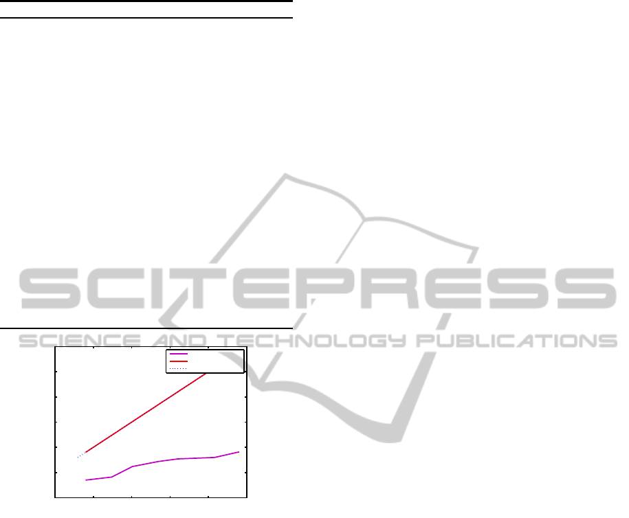
Figure 2 represents the bus CAN utilization decrease
after the modification of the WCTTs and periods and
after the removal of several tasks. After each task ad-
dition and when the initial utilization increases, the
new utilization is calculated according to the new pa-
rameters. It decreases and becomes less than 1. After
the task removal, we can get good results since the
utilization of the RCB does not exceed 1.
ReconfigurableCANinReal-timeEmbeddedPlatforms
361
Algorithm 2: TOOL.
1. Input: n periodic and aperiodic tasks
2. Input: n periodic and aperiodic messages
3. Calculate the initial processor utilization of the sys-
tem;
4. Calculate the initial capacity on the bus CAN;
5. Verify the feasibility;
6. Input: m added periodic and aperiodic tasks;
7. Input: m added periodic and aperiodic messages;
8.
for each reconfiguration scenario do
Calculate the capacity on CAN;
if U
S
≥ 1 then
Apply solution1 or solution2 or solution3;
end if
end for
9.
invoke algorithm ”1”;
10.
for each Reconfiguration scenario do
Calculate the new available space of each frame;
end for
11. Return to step 4;
0.5 1 1.5 2 2.5 3
0
0.5
1
1.5
2
2.5
3
U
(ia)
U
(i)
WCTTs modification
Periods modification
task removal
Figure 2: CAN bus utilization decrease.
9 CONCLUSION
In this work, we focus on the reconfiguration of RCB
that links several microcontrollers. We propose dif-
ferent solutions in order to guarantee a feasible sys-
tem and to minimize the utilization of the bandwidth
after any reconfiguration scenario. In our future work,
we plan to implement all these solution in a real case
study.
REFERENCES
Decreasing Algorithms. http://www.developerfusion.com/
article/5540/bin-packing/6/.
Electrical Engineering Catalog. http://
www.hik-consulting.pl/edu/files/IT-elektronika-
elektrotechnika- pomoce- naukowe.pdf.
B. D. Bui, R. P. and Caccamo, M. (2005). Real-
time Scheduling of Concurrent Transactions in Multi-
domain Ring Buses. IEEE Transactions on Comput-
ers.
C. Norstrm, K. S. and Ahlmark, M. (2000). Frame pack-
ing in real-time communication. Mlardalen Real-Time
Research Center., Sweden.
Davis, T. Bin Packing. http://www.geometer.org/
mathcircles.
E. G. Coffman, M. G. and Johnson, D. (1996). Approxi-
mation algorithms for bin packing: a survey. PWS
Publishing.
Gmbh, R. B. (1991). CAN Specification. J. Assoc. Comput.
Mach., Germany.
I. khemaissia, O. Mosbahi, M. K. and Bouzayen, W. (2014).
New Reconfigurable Middleware for Feasible Adap-
tive RT-Linux. pervasive and computing embedded
and communication systems., Lisbon, Portugal.
K. Sandstrom, C. N. and Ahlmark, M. (2000). Frame pack-
ing in real-time communication. Real-Time Comput-
ing Systems and Applications.
K. Tindell, A. B. and Wellings, A. (2000). Calculating Con-
troller Area Network (CAN) Message Response Times.
Control Engineering Practice.
L. Chaari, N. M. and Kamoun, L. (2002). Electronic con-
trol in electric vehicle based on can network. IEEE
International Conference on Systems.
Liu, C. L. and Layland, J. W. (1973). Scheduling algo-
rithms for multiprogramming in a hard real time envi-
ronment. J. Assoc. Comput. Mach.
Marino, A. and Schmalzel, J. (2007). Controller area
network for in-vehicle law enforcement applications.
IEEE Sensors Applications Symposium.
Navet, N. (1998). Controller area network [automotive ap-
plications]. The publishing company, London, 2nd
edition.
R. S. Marques, N. Navet, F. S.-L. (2005). Configuration
of in-vehicle embedded systems under real-time con-
straints. 10th IEEE Conference.
R. S Marquos, N. N. and Simon-Lion, F. (1998). Frame
packing under real-time constraints. The publishing
company, London.
X. Wang, H. C. and Ding, H. (1999). The application of
controller area network on vehicle. In Vehicle Elec-
tronics Conference.
ICINCO2014-11thInternationalConferenceonInformaticsinControl,AutomationandRobotics
362
