
A Novel Sea Wave Simulation Test Environment Construct for
Shipborne Weapons Systems
Chi He
1
, Guangling Dong
2,3
, Qiang Li
2
, Mengying Ye
4
and Hongqiang Wei
2
1
School of Mechatronic Engineering, CUST, 7089 Weixing Road, Changchun, China
2
Department of Test Technology, Baicheng Ordnance Test Center of China, Mailbox 108, Baicheng, China
3
School of Astronautics, Harbin Institute of Technology, 92 Xidazhijie Street, Harbin, China
4
Software Engineering Institute, East China Normal University, 3663 Zhongshanbei Road, Shanghai, China
Keywords: Shipborne Weapon System, Approval Test and Evaluation, Operational Test and Evaluation, Sea Wave
Impact, Flight Path, Simulation System.
Abstract: A key technology problem with respect to approval testing and evaluation is that of simulating sea wave
impact in shipborne weapons systems, both in terms of land-based and sea-based tests. There are two main
methods in use at present: the first method is to build large-scale water pool, in which the shipborne
weapons system under test is mounted to a special model ship; the second method is to simulate sea wave
impact via a six degree of freedom motion simulation platform. Because of their extremely high costs and
engineering implementation difficulties, the two methods have not generally been used in practice. In this
paper, a flight path and sea wave impact simulation system which transfer test data via CAN bus was
designed and developed, and five mathematical models of typical flight paths (such as a horizontal line
path) and three levels of sea wave impact models were established. The sea wave impact models were
superimposed to flight path models via equivalent theory and coordinate mappings; and realistic fighter
flights path and sea wave impact environments were, in shipborne weapons system land-based tests,
constructed via an input simulation in which the mixed signal is input to the control loop of weapon system
under test. The models and methods in this paper were used in a battery of naval gun approval tests, and the
tracking performances of the shipborne weapons systems were simulated via MatLab. The simulation test
results indicate that the new simulation method and system can meet the requirements of shipborne weapons
Operational Test and Evaluation (OT&E) protocols completely.
1 INTRODUCTION
Shipborne weapon system mainly include carrier-
borne main gun, antiaircraft gun, high speed missile
defense gun, and guided missile launching system,
etc, whose Approval Test and Evaluation (AT&E)
includes both land-based test and sea-based test.
Only get passed in land-based AT&E, could
shipborne weapon system be loaded on ship for sea
test. While in land-based test, how to simulate the
effect of sea wave impact to shipborne weapon
system has been an insoluble problem for decades
(He, C., et al, 2013).
In recent years, besides developmental test and
evaluation (DT&E), some relevant OT&Es are also
required in AT&E of shipborne weapon system.
OT&E is that test and evaluation conducted by an
independent OT&E agency to provide feedback on
system design and the systems potential to be
operationally effective and operationally suitable.
OT&E for shipborne weapon system in AT&E, also
known as initial OT&E, belongs to operational
evaluation of navy. The initial OT&E is conducted
on a production or production-representative system
using typical operational personnel in a realistic
combat scenario (Defense Acquisition University,
2012). In the AT&E of high-tech shipborne weapon
system, some problems as no evaluation means for
certain technical index and its operational
effectiveness, mutual restriction between test sample
size and confidence level of inference, unrealizable
boundary conditions, limited failure reproduction
methods, difficulties in providing near battlefield
environment and realistic target, etc, are inevitable
with conventional test theory and methods.
Therefore, in order to solve the above-mentioned
problems, research on simulation test and evaluation
technology is becoming more and more important,
203
He C., Dong G., Li Q., Ye M. and Wei H..
A Novel Sea Wave Simulation Test Environment Construct for Shipborne Weapons Systems.
DOI: 10.5220/0005088902030210
In Proceedings of the 4th International Conference on Simulation and Modeling Methodologies, Technologies and Applications (SIMULTECH-2014),
pages 203-210
ISBN: 978-989-758-038-3
Copyright
c
2014 SCITEPRESS (Science and Technology Publications, Lda.)

which has become a valid supplement means for
field live firing test.
Currently, many Chinese experts and technical
staff have carried out some research on simulation
test and evaluation in AT&E of shipborne weapon
system. The common methods include mathematical
simulation and hardware in the loop simulation
(HWIL), as used in simulation of sea wave impact
on shipborne weapon system (Cao, G. H., et al,
2009). Owing to its good performance price ratio
(Wang, X., Shen, T. S., and Zhou, X. D., 2004),
signal injection simulation method is used widely in
simulation of target properties, background and
interference, as literature (Wu, J. H., et al, 2012)
carries out theoretical research on injected
simulation test of closed loop for performance
evaluation of infrared capture and tracking
equipment, and literature (Du, H. J., Lei, J. and Yu,
H., 2010) studies the application of infrared dynamic
background simulation with injected technology. As
in M&S of target flight path, most achievements
focus on programming algorithm of unmanned flight
path (Fu, X. W. and Gao, X. G., 2004), optimal
design of path parameter based on target properties
(Bian, X. L., Sheng, H. J. and Dai, D. C., 2011), and
some advanced algorithms as artificial ant colony
algorithm and improved gravitational search
algorithm in path planning of unmanned air vehicles
(Liu, M., et al, 2011, Li, P. and Duan, H. B., 2012).
Studies on influence of sea wave impact to ships
are primarily computer-based simulation, such as
simulation of ship's motion on irregular random
wave (Yin, Q. and Chen, H. W., 2007), M&S for
IMU of shipborne weapons in the condition of sea
waves (Luo, Y., 2007). Some navy department has
developed a load simulation system for type AT&E
of naval gun servo system (Li, G., Xu, L. Q., and
Chen, K., 2004). Considering the features of land-
based test, technicians in Baicheng Ordnance Test
Center of China developed a sea wave impact
simulation system for land-based test of shipborne
weapons (He, C., Dong, Q. S., Han, Y. H., et al,
2009), which uses moment motor to simulate the
load of servo system (He, C., Dong, G. L, Cai, C. Y.,
et al, 2011).
Generally, four aspects are addressed in this
paper. Firstly, we introduce the design of sea wave
impact simulation system based on CAN bus and
Ethernet. Then, we build the impact model of sea
wave and kinematic model of ship on the sea. After
that, we build models for five kinds of typical
target’s flight path. At last, we realize the simulation
of sea wave impact through injection of ship
movement disturbance on standard target’s flight
path directives, which is based on the principle of
equivalent substitution. Thus, the problem of sea
wave impact simulation in land-based test of
shipborne weapon system is solved.
2 DESIGN OF SEA WAVE
IMPACT SIMULATION
SYSTEM
2.1 System Composition
Sea wave impact simulation system is designed as a
distributed measurement and control system based
on CAN bus, which takes on good environmental
adaptation, and can generate standard signal
automatically, flight path signal, and superposed
signal of flight path and sea wave impact. Besides, it
can carry out handshaking communications with
weapon system under test according to specific
protocols. Ethernet is adopted for communication
between front-end computer and control computer of
weapon system. Different kinds of data format and
communication protocols for various weapon system
are considered in the system design, which takes on
good generality and extensibility. System chart is
shown in figure 1.
Host Computer Displayer Printer
Shipborne Weapon System
Control Computer
Gun Control System
Target
Coordinat
e
Feed
Forward
Position
Feed Back
Standard Signal Flight Path Signal
Sea Wave Impact Signal
Front-end Computer
Twisted-pair
> 50m
Figure 1: System chart of sea wave impact simulation
system.
The sea wave impact simulation system is
composed of host computer, front-end computer and
communication network. In figure 1, dashed box
indicate control computer that generates control
instruction signals and gun control system of
shipborne weapon system under test.
SIMULTECH2014-4thInternationalConferenceonSimulationandModelingMethodologies,Technologiesand
Applications
204
2.2 Operation Principle
As a control equipment in DT&E of shipborne
weapon system, sea wave impact simulation system
substitutes weapon fire control system to control the
movement of naval gun and simulate the impact of
sea wave, its specific functions are as follows:
Generating five typical flight path’s signals to
drive shipborne weapon system;
Simulating the movement of ships according
to models of sea wave impact;
Superimposing effect of sea wave impact on
typical flight path’s signals based on the
principle of equivalent substitution;
Controlling shipborne weapon system with
superposed signal;
System self-checking and dangerous area
restriction for gun firing.
According to actual target flying parameters,
simulation system can generate typical flight path’s
signals to drive gun for real time target tracking, and
shoot at proper time. Thus, tracking and firing
accuracy of weapon system can be tested, which
provide technical gist for its DT&E.
Ship swing movement under different levels of
sea wave can be simulated according to sea
conditions in combat field of shipborne weapon
system, its effect can be mapped to flight path
through coordinate transformation and equivalent
substitution method. Thus, sea wave impact on
shipborne weapon system is modelled for land-based
test, to establish the natural environment conditions
for OT&E of weapon system.
3 COORDINATE SYSTEMS
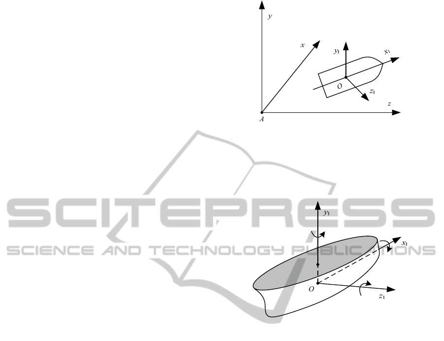
3.1 Earth Coordinate System
Earth coordinate system A-xyz is an east-north-up
coordinate system; it is also a static coordinate
system with origin A fixed on any earth surface
point. Axis Ax is located in horizontal plane with
north as positive direction; Axis Ay is perpendicular
to ground plane with upwards as positive; therefore,
according to the rule of right hand, axis Az is in
horizontal plane with east as positive direction.
Obviously, plane xAy is a vertical plane, while plane
xAz is ground plane, as shown in figure 2.
Figure 2: Earth coordinate system.
3.2 Hull Coordinate System
Ship hull coordinate system O-x
1
y
1
z
1
is a moving
coordinates system, as shown in figure 3.
Figure 3: Hull coordinate system.
In figure 3, origin O is usually fixed in gravity
center G of ships, Ox
1
is parallel with roll axis and
point to prow, vertical axis Oy
1
points upward, and
Oz is parallel with pitch axis and point to starboard.
Ox
1
, Oy
1
and Oz
1
are considered as roll axis, yaw
axis and pitch axis separately.
3.3 Coordinate System Transformation
Coordinate system transformation refers particularly
to coordinate transforming between earth coordinate
system and ship hull coordinate system. Making
translation of earth coordinate system A-xyz to take
on coincident origin as hull coordinate system,
relative attitude of hull coordinate system O-x
1
y
1
z
1
to
earth coordinate system A-xyz can be determined by
three attitude angles.
The pitching angle θ, yawing angle ψ, and rolling
angle γ are defined as follows:
Pitching angle θ: included angle between hull
longitudinal axis Ox
1
and horizontal plane. Included
angle θ with hull longitudinal axis upon horizontal
plane is positive; on the contrary, it is negative.
ANovelSeaWaveSimulationTestEnvironmentConstructforShipborneWeaponsSystems
205

Yawing angle ψ: included angle between
projection of hull longitudinal axis Ox
1
on horizontal
plane xAz and axis Ax. Yawing angle ψ is positive
while projection line of hull longitudinal axis is on
the anticlockwise side; on the contrary, it is
negative.
Rolling angle γ: included angle between Oy
1
and
vertical plane containing hull longitudinal axis Ox1.
Seeing along axis Ox
1
from ship stern, if Oy
1
lies on
the right-hand side of vertical plane, γ is positive; on
the contrary, γ is negative.
Three angle parameters defined above are also
known as hull attitude angles, which can be used to
derive transform matrix L(γ, θ, ψ) from hull
coordinate system Ox
1
y
1
z
1
to earth coordinate system
Axyz. We assume the origin and each coordinate axis
of hull coordinate system and earth coordinate
system coincide. Then, we get three elementary
matrixes by rotating angles of ψ, θ and γ around
corresponding axis in turning by the definition of
attitude angle. The product of these three elementary
matrixes is transform matrix L(γ, θ, ψ).
Certain vector (x, y, z)
T
in earth coordinate
system Axyz can be transform to hull coordinate
system Ox
1
y
1
z
1
via equation (1).
1
1
1
() () ( ) ( , , )
xzy
x
xx
y LLL yL y
zzz
(1)
Where
11 12 13
21 22 23
31 32 33
(,,)
aaa
Laaa
aaa
, a
11
=cosθcosψ,
a
12
= sinθ, a
13
= −cosθsinψ, a
21
= −sinθcosψcosγ +
sinψsinγ, a
22
= cosθcosγ, a
23
= sinθcosψcosγ +
cosψsinγ, a
31
= sinθcosψsinγ + sinψcosγ, a
32
=
−cosθsinγ, a
33
= sinθsinψsinγ + cosψcosγ.
4 MODELING OF STANDARD
TARGET FLIGHT PATH’S
SIGNAL
Generally, standard target flight path’s signals can
be divided into five basic types as horizontal
uniform speed linear path, horizontal uniform
acceleration linear path, gliding descent (with
uniform speed) path, diving flight (with uniform
acceleration) path and horizontal circling path with
constant speed.
4.1 Horizontal Linear Path
Horizontal linear paths include horizontal uniform
speed linear path and horizontal uniform
acceleration linear path, as shown in figure 4.
G
P
s
P
s
0
h
0
z
x
y
l
0
l
l
P
j
P
e
s
1
P
a
l
a
Figure 4: Schematic diagram of horizontal linear path.
In figure 4, P
s
is path starting point, P' is
projection of path starting point on horizontal plane,
P
a
is speedup point of target, P
j
is shortcut point, P
e
is path terminal point, G is position of gun; l is flight
path of target airplane, dashed line l' is projection of
flight path on horizontal plane. We take G as origin
of coordinate, and assume X-axis located in
horizontal plane pointing to north, Y-axis
perpendicular to horizontal plane pointing upwards,
and Z-axis perpendicular to X-axis pointing to east.
Thus, coordinate system of G-xyz is built.
Modelling parameters of horizontal linear path
are as follows:
Starting path s
0
(m): lateral distance between
path starting point and gun position. Both
horizontal linear paths indicate movement
path from starting point P
s
to shortcut point P
j
to terminal point P
e
, namely target starts
flying from s
0
, goes through path shortcut
point and in the end reaches s
1
to stop;
Terminal path s
1
(m): lateral distance between
path end point and gun position;
Speedup path l
a
(m): lateral distance between
acceleration point and gun position;
Speedup time T (s): Speedup duration time of
target flying;
Path altitude h
0
(m): vertical distance between
target and horizontal plane;
Lateral range l
0
(m): vertical distance between
gun position G and path projection l';
Target initial speed v
0
(m/s): initial flight
speed of target, referring to target linear speed
for circling path;
SIMULTECH2014-4thInternationalConferenceonSimulationandModelingMethodologies,Technologiesand
Applications
206
Target acceleration a (m/s
2
): constant
acceleration of target speedup flying;
Course angle θ (mil): included angle from
north to target flying direction with clockwise
as positive, which is used to determine travel
direction of target in horizontal plane.
Starting point coordinates of horizontal linear path
can be expressed as equation (2).
22
000
00
22
000
0
0
cos
sin
arctan
xls
yh
zls
l
s
(2)
On speedup point, we get the equation (3). And
at terminal point of speedup, we get the equation (4).
22
10
10
22
10
0
cos
sin
arctan
a
a
a
xll
yh
zll
l
l
(3)
222
20 0
20
222
20 0
0
2
0
1
()cos
2
1
()sin
2
arctan
1
2
a
a
a
xllvTaT
yh
zllvTaT
l
lvT aT
(4)
4.1.1 Mathematical Model of Horizontal
Uniform Speed Linear Path
While the target takes on horizontal uniform speed
linear motion, we get the equation (5) under G-xyz
coordinate system.
00
0
00
() cos
()
() sin
xt x v t
yt h
zt z v t
(5)
4.1.2 Mathematical Model of Horizontal
Uniform Acceleration Linear Path
While the target takes on horizontal uniform
acceleration linear flight, we get the equation (6).
00 0
01 00
02 0
0
00 0
01 00
02 0
cos [0, ]
() cos ( , ]
cos ( , ]
()
sin [0, ]
() sin ( , ]
sin ( , ]
e
e
xvt t t
x
txs tttT
x
sttTt
yt h
zvt t t
zt z s t t t T
zs ttTt
(6)
Where
2
10 0
1
()
2
s
vt a t t
,
2
20 0
1
()
2
s
v t aT aT t t T
.
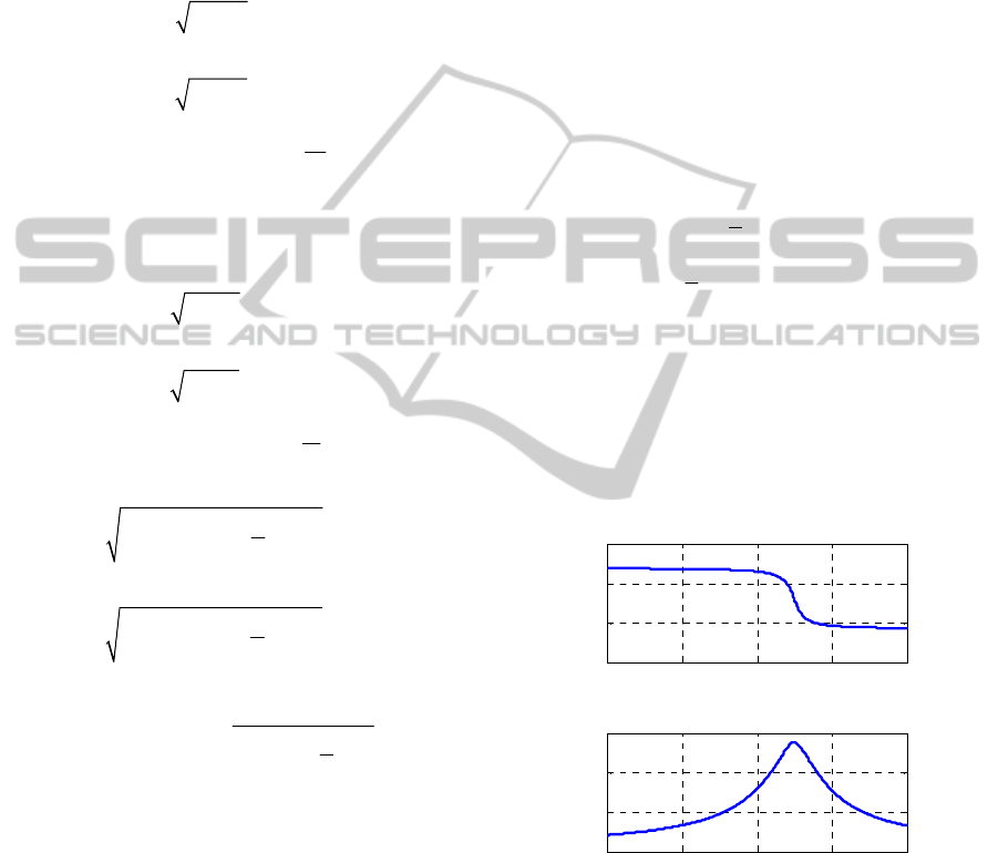
4.1.3 Programming
Programming with MatLab is done according to
mathematical model of horizontal linear path.
Taking target motion acceleration 0 m/s
2
, we get
simulated directive signal for horizontal uniform
speed linear path, as shown in figure 5.
0 10 20 30 40
-4
-2
0
2
Time (s)
Directive (rad)
Azimuth
0 10 20 30 40
0
0.5
1
1.5
Time (s)
Directive (rad)
Elevation
Figure 5: Simulated directive signal for horizontal uniform
speed linear path.
4.2 Simulation of Target Path Signal
As to the above-mentioned path signals, azimuth
directives for gun control system can be calculated
as the equation (7). And elevation directive angle as
the equation (8).
ANovelSeaWaveSimulationTestEnvironmentConstructforShipborneWeaponsSystems
207
()
() arccot
()
x
t
t
zt
(7)
22
()
( ) arctan
() ()
yt
t
x
tzt
(8)
5 PATH SIGNAL MODELLING
WITH THE INFLUENCE OF
SEA WAVE
5.1 Equivalent Substitution Method
Equivalent substitution is a common method in
scientific research. As a quick and valid means for
solving physical problem, the idea and method of
equivalency are of far reaching importance in AT&E
method research of weapon system.
Equivalent substitution method transform the
actual complicated physical problem and process to
an equivalent, simple and easy to research problem
or process, under the guarantees of some kind of
equal effect (characteristic and relationship).
5.2 Path Signal Model Under Sea Wave
Interference
Additional motions as rolling, pitching, yawing and
heaving would occur while ships sailing in wave.
Owing to their minor amplitude, yawing and
heaving can be ignored, and so we can assume the
additional motions of ships in sea wave are mainly
rolling and pitching. Roll and pitch cause hull
attitude change in real time, which makes the trace
command of naval gun to adjust according to hull
attitude angle in order to track target flight path
normally. Therefore, directive signal of naval gun's
tracking target path under sea wave interference can
be simulated by modified standard path signal with
hull attitude angle. If we adopt this kind of modified
path signal, actual working conditions of naval gun
in sea wave could be equivalently simulated, which
makes performance evaluation of weapon system
more rational and credible.
Steps for modelling of path signal under sea
wave interference are as follows:
Build up kinematic model of ships in sea
wave;
Get transition matrix from earth coordinate
system to hull coordinate system according to
attitude angle of ship motion;
Transform target path coordinates from earth
coordinate system to hull coordinate system;
Calculate azimuth directive and elevation
directive in hull coordinate system by triangle
transformation formula;
Save directives in target path flying time, get
path signal model under sea wave
interference.
5.3 Simulation Analysis
Simulation and analysis mainly include modelling of
ship movement, path signal modelling in earth
coordinate system, coordinates transformation from
earth coordinate system to hull coordinate system,
and path signal tracking simulation under sea wave
interference.
5.3.1 Ship Movement Simulation
Programming for ships motion in sea wave is done
according to related literatures, which realizes the
simulation of ship movement in sea wave.
We get simulation result for attitude angle of
ship movement in sea wave as shown in figure 6,
where heavy real line part is taken for modelling of
path signal under sea wave interference.
0 50 100 150 200
-10
0
10
Time (s)
Roll angle (°)
Rolling angle
0 50 100 150 200
-5
0
5
Time (s)
Pitch angle (°)
Pitching angle of ship
Attitude Tracking part
At t it ude Tracking part
Figure 6: Simulation of ship movement in sea wave.
5.3.2 Path Signal Modelling Under Sea
Wave Interference
Actually, the path signal is azimuth and altitude
angle of target's flying path seeing from hull
coordinate system. Therefore, if we take ship
attitude angle in earth coordinate system as the
coordinate rotation angle for building coordinate-
SIMULTECH2014-4thInternationalConferenceonSimulationandModelingMethodologies,Technologiesand
Applications
208
transformation matrix, three-dimensional coordinate
of target can be transformed from earth coordinate
system to hull coordinate system, and then target
path signal in hull coordinate system could be
obtained. Modelling of gliding descent (diving
flight) path, circling path, horizontal uniform speed
(acceleration) linear path under sea wave
interference can be realized according to this idea.
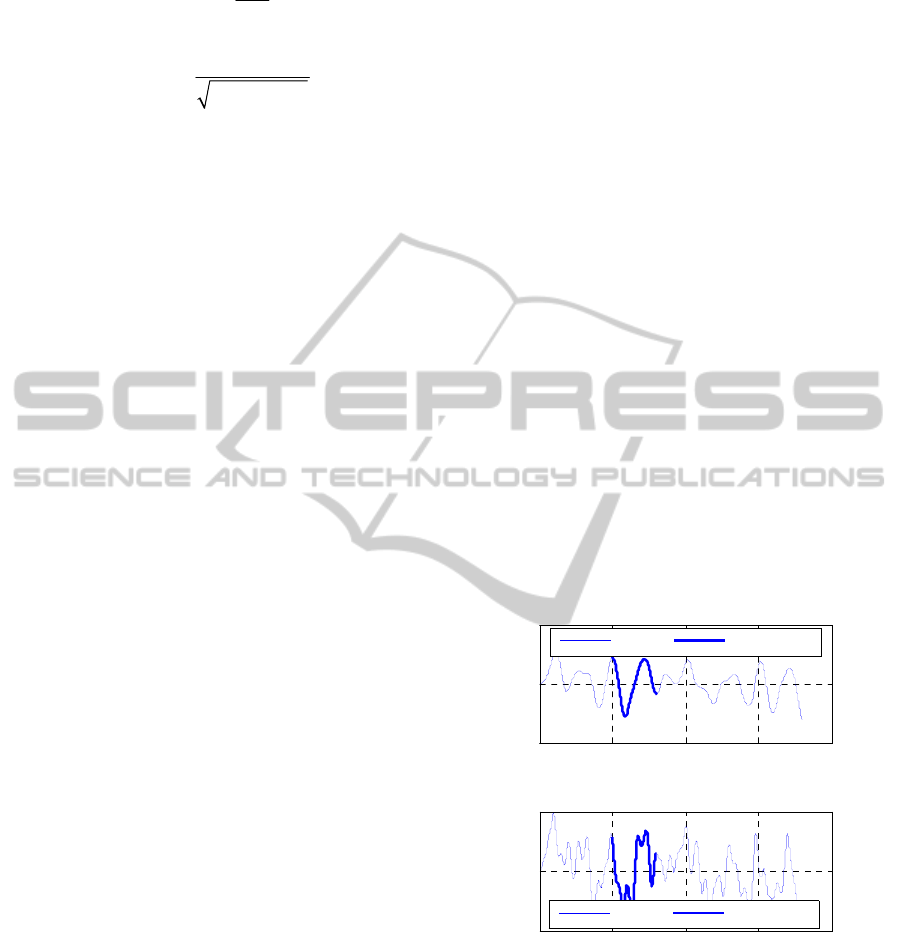
Take gliding descent (diving flight) path as an
analysis example, if we take the bold real line part in
figure 6 as the attitude of ship motion, target path
signal under sea wave interference is shown in
figure 7 where real line indicates standard path
signal in earth coordinate system, and dot dash line
is path signal under sea wave interference. In this
way, path signal disturbed by ship attitude change in
sea wave has much difference to static ship attitude.
0 5 10 15 20
0
1
2
3
Time (s)
Azimuth (rad)
Directives
Clear Noisy
0 5 10 15 20
0
0.5
1
Time (s)
Elevation (rad)
Noisy Elevation Directives
Clear Noisy
Figure 7: Path signal modelling under sea wave
interference.
6 TRACKING SIMULATION OF
GUN CONTROL SYSTEM
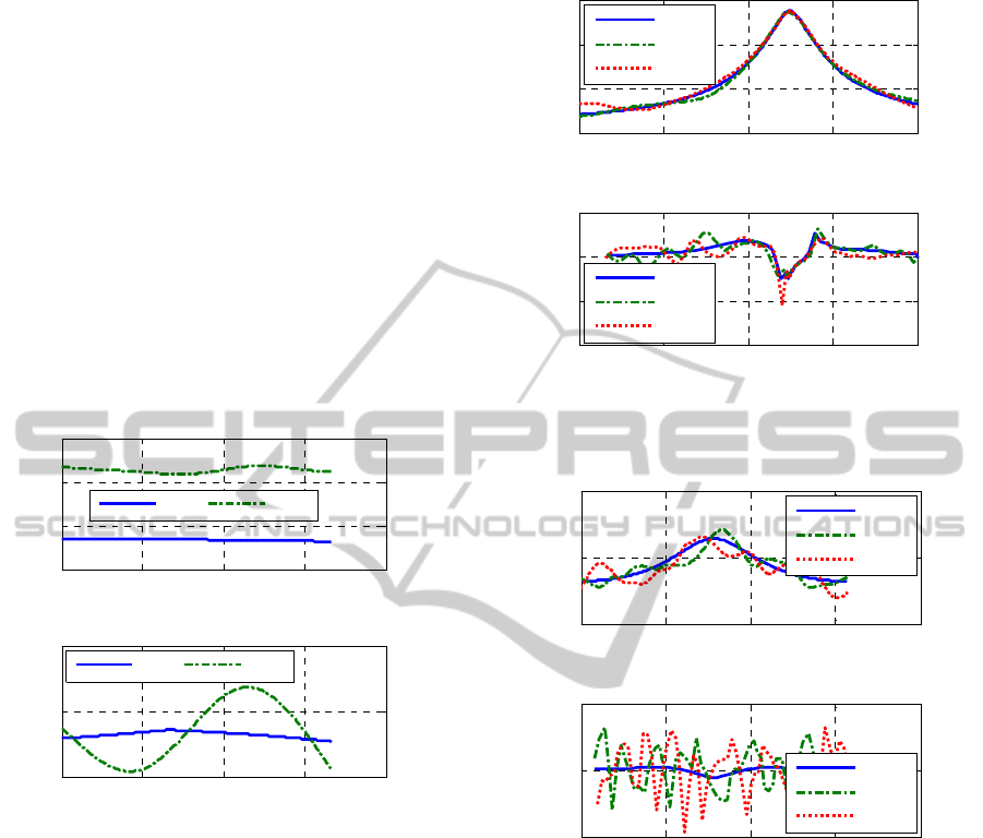
We take five flight paths under three levels of sea
condition (0, 4 and 7) to carry out simulation test for
operational performance evaluation of certain type
of shipborne weapon system.
Figure 8 and figure 9 shows respectively
directives and tracking error for horizontal uniform
speed linear path and circling path with constant
speed. Where, solid lines indicate clear standard path
directive and tracking error without sea wave
interference, dot dash lines indicate situations under
level 4 sea condition, and dotted lines represent
situations under level 7 sea condition.
0 10 20 30 40
0
0.5
1
1.5
Time (s)
Elevation (rad)
Directives
0 10 20 30 40
-4
-2
0
2
Tiem (s)
Elevation (mrad)
Tracking error
level 0
level 4
level 7
level 0
level 4
level 7
Figure 8: Horizontal uniform speed linear path.
0 20 40 60 80
0
0.2
0.4
Time (s)
Elevation (rad)
Directives
0 20 40 60 80
-2
0
2
Tiem (s)
Elevation (mrad)
T racking error
level 0
level 4
level 7
level 0
level 4
level 7
Figure 9: Horizontal circling route with constant speed.
7 CONCLUSIONS
In this paper, we propose a novel sea wave impact
construction method for land-based AT&E of
shipborne weapon system according to the
requirements of OT&E. Based on the established
ship movement model in sea wave and target flight
path model, we use the equivalent substitution
method and coordinate transformation to superpose
sea wave impact effect on ships to the standard flight
path signals. Thus, a novel multiplexed control
signal is constructed, which realizes the simulation
of real marine environment in land-based test of the
shipborne weapon systems.
ANovelSeaWaveSimulationTestEnvironmentConstructforShipborneWeaponsSystems
209

The designed sea wave impact simulation system
can be used to substitute fire control system of
shipborne weapon system in land-based test, which
realizes the simulation of flight path signal and sea
wave impact effect on ships by multiplexed control
signal input method. In this way, the requirements of
OT&E for shipborne weapon system are satisfied.
The novel method has been verified in T&E of
certain type of naval gun weapon system. Tracking
errors for different flight path under three levels of
sea conditions (level 0, 4, and 7) are listed in Table
1.
Table 1: Maximum tracking error of target path under
different sea conditions.
Path type
Level 0
h
1/3
= 0 m
Level 4
h
1/3
= 1.2 m
Level 7
h
1/3
= 6.0 m
A 1.0575 1.2167 2.2064
B 1.7228 1.8463 2.0570
C 1.8087 2.0232 2.5734
D 1.8097 1.9197 3.0981
E 0.2379 1.2565 1.9102
In table 1, A denotes horizontal uniform speed
linear path; B is horizontal uniform acceleration
linear path; C is gliding descent path; D is diving
flight path; E is circling path.
As shown in table 1, maximum tracking errors
under level 4 sea condition for five typical target
paths rise from 6.07% to 428.16% compared with
that under level 0 sea condition, while maximum
tracking errors under level 7 sea condition could rise
from 19.40% to 702.94%. It is thus clear that
tracking errors of shipborne weapon system for
different flight paths diverse from each other, and
they increase according to sea wave condition level.
The sea wave impact simulation system and the
method introduced in this paper have been
successfully applied in land-based AT&E of many
weapon systems. Application results indicate that the
system takes on features of correct principle,
scientific method, easy to operate, high measuring
accuracy, and stable control characteristics. Besides,
the application of sea wave impact simulation
system could shorten test period remarkably with
less consumption and improved quality by providing
a realistic target flight path in a realistic combat
scenario (sea battlefield environment).
REFERENCES
Bian, X. L., Sheng, H. J. and Dai, D. C., 2011. Analysis on
Requests of Unmanned Aerial Vehicle False Target
Jamming Validity. In SHIPBOARD ELECTRONIC
COUNTER MEASURE.
Cao, G. H., Dong, G. L., Dong, Y. L., et al., 2009.
Simulation Study of Ocean Wave Impact Load for
Shipborne Weapon System's Terrestrial Type
Approval Test. In Journal of System Simulation.
Defense Acquisition University, 2012. TEST AND
EVALUATION MANAGEMENT GUIDE, The Defense
Acquisition University Press, 6
th
Edition.
Du, H. J., Lei, J. and Yu, H., 2010. Injected Modelling and
Simulation of Dynamic Infrared Scene. In Infrared
and Laser Engineering.
Fu, X. W. and Gao, X. G., 2004. Study on a Kind of Path
Planning Algorithm for UAV. In Journal of System
Simulation.
He, C., Dong, G. L., Cai, C. Y., et al, 2011. Design of
Shock Simulation System for Shipborne Weapons
Based on Electro hydraulic Servomotor. In the 2
nd
International Conference on Mechanic Automation
and Control Engineering.
He, C., Dong, Q. S., Han, Y. H., et al, 2009. Design for
Load Simulation System of Naval Gun Servo System.
In Journal of System Simulation.
He, C., Huang. C. F., Li, Q., et al., 2013. Development on
New Sea Wave Simulation System for Shipborne
Weapons. In Journal of System Simulation.
Li, G., Xu, L. Q. and Chen, K., 2004. Study and
Realization of Load Simulation of Servo System of
Naval Gun. In GUN LAUNCH
&
CONTROL
JOURNAL.
Li, P. and Duan, H. B., 2012. Path planning of unmanned
aerial vehicle based on improved gravitational search
algorithm. In Sci China Tech Sci, SCIENCE CHINA
PRESS.
Liu, M., Zou, J., Feng, X., et al., 2011. Smooth trajectory
planning of an unmanned aerial vehicle using an
artificial bee colony algorithm. In CAAI Transactions
on Intelligent Systems.
Luo, Y., 2007. Modelling and Simulation for IMU of
Shipboard Weapons in the Condition of Waves. In
Journal of Naval Aeronautical Engineering Institute.
Wang, X. W., Shen, T. S. and Zhou, X. D., 2004. An
Evaluation System of Infrared Imaging Guiding
Algorithm Based on the Signal Injection Simulation.
In Journal of System Simulation.
Wu, J. H., Li, H., Xu, Z. L., et al., 2012. Theoretical
Research on IR Capturing and Tracking Device
Simulation Based on Digital Image Injection. In
Infrared and Laser Engineering.
Yin, Q. and Chen, H. W., 2007. The Simulation of Ship’s
Motion on Random Wave. In J. Microelectronics &
Computer.
SIMULTECH2014-4thInternationalConferenceonSimulationandModelingMethodologies,Technologiesand
Applications
210
