
New Solutions for Fault Detections and Dynamic Recoveries of Flexible
Power Smart Grids
Syrine Ben Meskina
1
, Narjes Doggaz
2
and Mohamed Khalgui
3
1
LISI, ISI, University Tunis-El Manar, Tunis, Tunisia
2
LIPAH, FST, University Tunis El-Manar, Tunis, Tunisia
3
LISI, INSAT, University of Carthage, Tunis, Tunisia
Keywords:
Smart Grid, Fault Detection, Dynamic Recovery, Multi-agent System, Mobile Agent, Local Solution,
Distributed Solution.
Abstract:
This research paper deals with fault detections and dynamic recoveries of electrical smart grids that should be
flexible and automatically adapted at run-time when faults occur on lines or devices. These grids are composed
of three levels of power lines: High Voltage Lines (44KV ), Medium Voltage Lines (11KV ), and Low Voltage
Lines (380V ). In order to control the complexity of detection and deduction, we propose new relations between
faults. We define also a multi-agent architecture to allow dynamic recoveries where two types of agents are
defined: static agents and mobile agents. Static agents have as a task the detection of local faults on power
lines and the recovery of their normal behaviors by using a local knowledge-base. The mobile agents are
created to dynamically move on lines and to find new solutions when no local solution is found. To validate
and test our approach, we present experimental results showing the originality of the paper’s contribution by
assuming a case study.
1 INTRODUCTION
Faults and blackouts may be caused by the worsen
system conditions such that short-circuit, overloaded
loss of power plants, protection hidden failure... (Lu
et al., 2006). Around the world, there are many defini-
tions of smart grids including big amounts of multidi-
mensional characteristics. Smart grids can be seen as
the modernization of the current electric grid through
the intensive use of communication technologies, the
integration of renewable and green energies to decar-
bonize power systems, as well as the improvement of
both security and reliability of the network and, even,
the addition of new smart electric hardware devices
(like meters, storage devices, sensors...). The impor-
tance of the damages caused by power breaks and out-
ages, as well as, the classical centralized production
architecture have encouraged and inspired researchers
to work on it in order to bring changes on power grids
and, even, on their infrastructures. The majority of the
related works deployed Multi-Agent Systems (MAS)
in the domain of power networks to ensure a commu-
nication between several components of the network
and to organize their tasks. (Rohbogner et al., 2012)
discusses what is an agent in the context of smart grids
and (Endriss et al., 2004) discusses the problem of
checking an agent’s conformance to protocol.
In this paper, we address new problems related to
the performance of Smart Grids such as the deduction
of faults as soon as possible and the optimal recovery
with feasible run-time solutions. We propose, a novel
agent-based approach for the fault detection and re-
covery in the context of electrical smart grids when
faults occur on lines or devices. To control the com-
plexity of detection and fault deduction, we propose
new relations between faults to define our new effi-
cient fault resolution method. This new fault catego-
rization allows the forecast of other consequent faults
by deduction. We define also a multi-agent architec-
ture to allow dynamic recoveries composed of three
types of agents. To reduce the time required for the
system recovery, our solution ensures the update at
run-time of data base agent when new solutions are
found. These solutions may be, directly, used when
the same fault occurs again. The originality of our
work lies, also, in the agent mobility allowing; (i)
a speed and useful information exchange, (ii) a de-
centralized new solution as mobile agents can move
over the grid and (iii) the best solution at any time
as the calculus is done at real-time. In Section 2, we
370
Ben Meskina S., Doggaz N. and Khalgui M..
New Solutions for Fault Detections and Dynamic Recoveries of Flexible Power Smart Grids.
DOI: 10.5220/0005091303700377
In Proceedings of the 11th International Conference on Informatics in Control, Automation and Robotics (ICINCO-2014), pages 370-377
ISBN: 978-989-758-039-0
Copyright
c
2014 SCITEPRESS (Science and Technology Publications, Lda.)

present the state of the art. In Section 3, we formalize
and characterize smart grids, fault detection and de-
duction and propose new relations between faults. In
Section 5, we expose the deployed multi-agent sys-
tem to be composed of static and mobile entities in
order to search, respectively, local and distributed so-
lutions. Section (6) presents our system recovery ap-
proach. And in Section 7, we test our solution for
several scenarios in a simulated case study.
2 STATE OF THE ART
Over the last years, many researchers worked on dif-
ferent topics and concepts relative to power networks
and smart grids. There is an important number of
works relative to the problems of fault detection in
power systems, self-healing and system recovery...
The majority of the proposed approaches in the liter-
ature use MAS. A MAS is a decentralized system to
be composed of a set of agents placed in some envi-
ronment of software agents (McArthur et al., 2007b).
(Rohbogner et al., 2012) shows that distributed hier-
archical control structures are more efficient than cen-
tral ones. A new useful concept appears which con-
sists of dividing the network on subnetworks, called
micro-grids or ”islands”, is highlighted. Distributed
infrastructures decentralizing the control imply, gen-
erally, the deployment of Distributed Energy Re-
sources (DER). Based on this concept, (Chen et al.,
2010) showed that it is possible to reduce the like-
lihood of dramatically cascading failures, even, when
integrating a small number of local generators into the
power grid. In fact, thanks to this strategy based on
DER and decentralized power system control, (Rah-
man et al., 2007) proposed a concept of micro-grids
working during normal operation and, also, in case of
failures, as islands independent of the main grid and
supplied by local generators. (McArthur et al., 2007a)
and (McArthur et al., 2007b) investigates and stud-
ies the higher value-added by (MAS) to power indus-
try. (Tate and Overbye, 2008) uses the Phasor Mea-
surement Unit to detect simple line outages and (Tate
and Overbye, 2009) uses it to detect double line out-
ages and to identify network parameter errors. Other
works on failure identification and diagnosis include
(Cai et al., 2010), (Calderaro et al., 2011), (He and
Zhang, 2010) and (Russell and Benner, 2010). (Vy-
atkin et al., 2010c) proposes a distributed MAS com-
posed of a number slave agents called BAGg and only
one unique master agent called FAG - centralizing
the control in the power grid system and achieving
a self-healing action through fault location and power
restoration. This MAS architecture was proposed in
(Nagata and Sasaki, 2002) and was used, also, in
(Zhabelova and Vyatkin, 2012) integrating Intelligent
Logic Nodes for self-healing power system in case of
circuit ruptures. These two industrial standards were
combined, in (Vyatkin et al., 2010b), to develop an
intelligent control architecture for smart grids.
After these short observations on related works,
we draw the following conclusions. As we previously
mentioned, there are many research works focussed
on fault detection and self-healing in power systems.
Some of them detect and repair only one type of en-
countered fault(s) but, neither of them studies the con-
sequent faults. For example, (Vyatkin et al., 2010a)
handles the case of only one fault type occurs (elec-
tricity break due to a tree falling on an electric line).
In our paper, we are looking for formalizing the strat-
egy of fault detection and resolution. A step of fault
analysis and categorization is necessary to guide the
resolution strategy. In the other hand, we note that
the majority of the proposed solutions are based on
MAS deploying many agents making the communi-
cation process very expensive. Rahman and al. pro-
poses, in (Rahman et al., 2007), an efficient approach
of power systems self-healing based on specialized
micro-grids but it is very expensive in terms of com-
munication costs (as they deploy 7 agents). They re-
duced the number of agents to 4, in (Pipattanasom-
porn et al., 2009), in order to decrease the response
time but the used fact bases are inextensible. (Vy-
atkin et al., 2010c) deploys only a unique one master
agent FAG and multiple BAGs leading to a centralized
control power system and to a big number of BAGs.
Whence, it is important to minimize the number of
agents in order to reduce the required communication
costs. In our approach, we propose a small number of
agents to be deployed and to instantiate mobile agents
in order to reduce the required response time in order
to find a solution.
3 SMART GRID
CHARACTERIZATION
Generally, electric grids involve three voltage lev-
els: High Voltage Line (HVL), Medium Voltage Line
(MVL) and Low Voltage Line (LVL). Commonly, we
have principal lines which are operational and emer-
gency lines used when the first ones are in failure.
In our study, the electric grids are formed by three
principal electric components interconnected through
electric lines. These components are: (i) Power
Generators (PG) that produce high voltage energy
transported through HV L. (ii) Down Power Trans-
formers (DPT ) that transform the received electric-
NewSolutionsforFaultDetectionsandDynamicRecoveriesofFlexiblePowerSmartGrids
371

ity from a voltage level to the lower one. We con-
sider two types of power transformers: The Medium
Voltage Transformer (MV T) and the Low Voltage
Transformer (LV T ). (iii) Consumers (as end-users
in electrical grids): we distinguish Medium Con-
sumers (MC) which are supplied by MV T through
MV L and Low Consumers(LC) which are supplied by
LV T through LV L.
In our system each component and electric line C
is characterized by:
1 - its activation state, A(C), as in(1):
A(C) =
0 , i f C is deactivated
1 , i f C is activated
(1)
2 - its voltage level, VoltLevel(C), as in (2):
VoltLevel(C) =
1, i f C ∈ high voltage level
2, i f C ∈ medium voltage level
3, i f C ∈ low voltage level
(2)
Each High Voltage Line L is defined by its trans-
ported load, TranspL(L). While, the Medium and
Low Voltage Lines L
i
are defined by their distributed
load DistL(L
i
).
The Power generators are characterized by the pro-
duced power ProdPow. While each power trans-
former X is characterized by its transformed power
Trans f Pow(X) and its priority. The priority of a
transformer X, pr(X), is calculated by equation (3):
pr(X ) =
n
∑
i=1
(pr(S
i
))/
m
∑
j=1
pr(P
j
) (3)
where S
i
is a supplied device, P
j
is a power grid de-
vice, n is the number of supplied devices by X and m
is the the number of all power grid’s devices.
Each consumer X is characterized by its:
1 - rank, rank(X), which is its relative place in the
supplying line,
2 - priority, pr(X), which represents the priority of the
consumer X.
3 - required load, ReqLoad(X), which represents the
load to need,
4 - received load, ReceivLoad(X ), which is calculated
by summing the loads distributed by the n incoming
lines L as mentioned in (4).
ReceivL(X) =
n
∑
i=1
(DistL(L))) (4)
4 SYSTEM
CHARACTERIZATION AND
FAULT CATEGORIZATION
The robustness of electrical grids is proven through
their ability of managing and facing all eventual sub-
merging problems. In this section, we propose a set
of minimum conditions characterizing the system.
4.1 System Operating Conditions
To insure the healthy operation of the electric grid, the
following conditions have to be verified.
1 - Activation Constraint: The activation states of all
involved electric components have to be conserved.
For a High Voltage Grid, this condition is defined by:
(A(PG) = 1) ∧ (A(HV L) = 1) ∧ (A(MV T ) = 1) (5)
2 - Stability Constraint: The stability of the power
grid must be maintained by keeping the frequency of
all electric components and the voltage of all electric
lines, approximatively, equal to the respective pre-
fixed default values f
0
and U
0
. For a High Voltage
Level, the stability constraint is defined by:
( f req(PG) ≈ f
0
) ∧ (volt(HV L) ≈ U
0
)
∧( f req(MV T ) ≈ f
0
)
(6)
3 - Flowing Load Constraint: The safe and secure
operation of power systems depends, also, on loads
flowing into the grid. In fact, they must respect the
capacities of the deployed components. These loads
must, also, respect the constraint relative to both re-
quired and received loads by a consumer X as in (7).
ReqL(X) ≤ ReceivL(X) (7)
To avoid the under-voltage and over-voltage prob-
lems, each consumer X should be, sufficiently, sup-
plied. Therefore, the received loads should not be less
than their minimum capacities and should not exceed
the devices capacities. The violation of one of these
constraints leads to faults.
4.2 Fault Classification
The encountered faults can, easily, propagate through
electric lines from the sub-grid on which it occurs to
another one as the power system is a mesh network
to be composed of inter-connected electric compo-
nents. We define faults as consequences of one or
some unsatisfied constraints. Based on the constraints
presented in Section 4.1, the faults that can occur on
power grids may be; switching-off (deactivation), in-
stability, under-voltage, over voltage and isolated sub-
grids. The open-circuits present a consequent fault to
the violation of constraint 1 or 2 or both of them. The
consequences of this fault are summarized by Table
1. As the dissatisfaction of only one constraint can
engender multiple faults, we look for minimizing the
ICINCO2014-11thInternationalConferenceonInformaticsinControl,AutomationandRobotics
372

Table 1: Isolated sub-grids constraints.
Fault origin Isolated Sub Grid Consequences
f req(PG) 6= f
0
A(PG) = 0 ∧ A(MV T ) = 1 ∧ A(HV L) = 1
ProdPow(PG) = 0 ∧ TranspL(HV L) = 0
∧ Trans f Pow(MV T ) = 0
f req(MV T) 6= f
0
A(PG) = 1 ∧ A(MV T ) = 0 ∧ A(HV L) = 1 Trans f Pow(MV T ) = 0
volt(HV L) 6= U
0
A(PG) = 1 ∧ A(MV T ) = 1 ∧ A(HV L) = 0
TranspL(HV L) = 0 ∧ Trans f Pow(MV T )
= 0
faults to be resolved and guiding the search for solu-
tions. For that, we propose new definitions for domi-
nant and equivalent faults based on new relations. We
denote the fault set by F and the i
th
fault by F
i
such
that: F
i
∈ F/i ∈ N.
Definition1: Dominant Fault. Let F
i
and F
0
be,
respectively, a fault and a subset of faults such that
F
0
⊆ F. Let us consider a component X connected to
a set of components Y such that |F
0
| = |Y |. A fault F
i
on a component X is said to be dominant of a fault F
j
on a component Y
j
and noted by: F
i
(X) → F
j
(Y
j
) if
for each F
j
∈ F
0
, Y
j
∈ Y and j = 1,...,|F
0
|:
VoltLevel(X) < VoltLevel(Y
j
)
or
VoltLevel(X) = VoltLevel(Y
j
) and
rank(X ) < rank(Y
j
)
(8)
The resolution of either the dominant or the domi-
nated fault(s) resolves the problem. This strategy al-
lows to reduce the required time of resolution.
Definition2: Equivalent Fault. Let F
i
and F
j
be two
faults. Let us consider two connected components X
and Y . The faults F
i
and F
j
, respectively, on the com-
ponents X and Y are said to be equivalent and noted
by: F
i
(X) ⇔ F
j
(Y ) if
VoltLevel(X) = VoltLevel(Y ) and rank(X ) = rank(Y )
(9)
In fact, the resolution of only one of the equivalent
faults can resolve the problem. These new relations
allow us to control and reduce the complexity of faults
by deduction. The advantage is, particularly, ob-
served in the case of multiple equivalent faults, as we
are focused on resolving only one of them.
5 NEW ARCHITECTURE FOR
FLEXIBLE SMART GRIDS
The resolution of the occurred faults can be done, ei-
ther, locally by taking a simple and systematic reac-
tion or by searching new solutions among the other
sub-grids. We propose, then, the use of multi-agent
paradigm to implement our distributed system decen-
tralizing the control. It ensures the fault detection and
deduction as well as the real time resolution to pro-
vide the best solution. Our MAS is composed of three
types of software agents:
- Reconfiguration Agent: Each RAgent is responsi-
ble of the continuous supervision and maintaining of
the healthy operation of the power sub grid under its
scope. It is composed of a set of rules describing its
behavior.
- Mobile Agent: A MAgent is a software entity mov-
ing, through electric lines, among the connected com-
ponents of the smart grid to collect some information.
- Data Base Agent: The DBAgent is responsible of
the management of the data base relative to the power
system. It contains, mainly, the new solutions found
by our MAS system as well as all the information
relative to the whole power grid structure as well as
the history of all the encountered faults and the cor-
responding solutions. It may be requested by both
RAgent and MAgent about information relative to the
power system. It should update its data base for each
new solution found by MAgent. The DBAgent may
be requested to avoid searching solutions for prob-
lems already resolved.
In order to reduce the communication cost, we asso-
ciate one RAgent to each electrical sub-grid. Hence,
we assign one RAgent to each PG, MV T and LV T .
The RAgents have, then, to supervise the concerned
component as well as the components directly sup-
plied belonging to the voltage level below. We de-
ploy only one central DBAgent (Figure 1). In fact,
the number of DBAgents depends of the whole con-
sidered grid size and, also, of the cardinality of sub-
grids formed from the global grid, as well as, of the
size of knowledge to be stored.
6 SYSTEM RECOVERY
In the current section, we present how our MAS op-
erates according to the power system circumstances.
6.1 Fault Detection and Local Solutions
The RAgent sensors must, continuously, observe their
environment in order to detect all changes and anoma-
NewSolutionsforFaultDetectionsandDynamicRecoveriesofFlexiblePowerSmartGrids
373
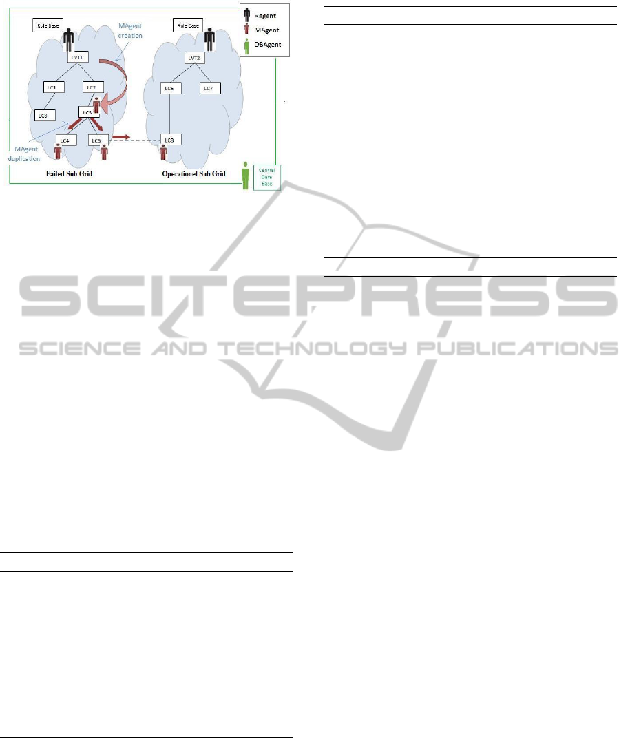
Figure 1: Example of agent assignment: attributing one
RAgent to each sub-grid, MAgent are created by RAgent
which can be cloned in bifurcation and unique DBAgent to
the overall power grid.
lies (unsatisfied constraint) on any electric compo-
nent. When a fault is detected on the component X,
the concerned RAgent begins by isolating the compo-
nent or line responsible of this anomaly (X) such it is
presented by Algorithm 1. Then, the RAgent in ques-
tion categorizes the occurred fault as it is described
by Algorithm 2 in order to guide the search for local
solutions where F is the fault detected on X. A local
solution consists of finding a deactivated emergency
line belonging to the supervised sub-grid SG and sup-
plying, sufficiently, X as it is described in Algorithm
3. When there is more than one local solution, the
RAgent chooses the one having the bigger remaining
load according to the (10).
Maximize( DistL(eL) − ReqL(X) ) (10)
Algorithm 1: Fault Detection and Isolation.
Require: SensorDetection 6=
if ∃ FrequencyProblem(X) then Isolate(X)
if ∃ VoltageProblem(L) then Isolate(L)
if ∃ Isolated(X) then Categorize the occurred faults
if no LocalSolution then
Request DBAgent(Problem)
if ∃ Solution in DB then call Effectors
else create MAgent
if ∃ Under-voltageProblem OR ∃ Over-
voltageProblem then create MAgent
When no local solution is found, the RAgent requests
the DBAgent about a solution already found for
the encountered problem. If no solution for the
occurred fault is stored in the data base, the RAgent
searches for a cooperative solution from the neighbor
sub-grids. For that, the RAgent creates an MAgents to
Algorithm 2: Fault Categorization.
Require: F: the detected fault
if F is dominant fault then
call(RAgent Local Solution) on the component
corresponding to the dominant fault
if no found solution for the dominated fault then
call(RAgent Local Solution) on the compo-
nents corresponding to the dominated faults
end if
end if
if F is an equivalent fault then
call(RAgent Local Solution) on the components
corresponding to the equivalent faults
end if
Algorithm 3: RAgent Local Solution.
if ∃ deactivated emergency line incoming to X
then
choose the one having the bigger positive re-
maining load
call effectors to execute solution
else if no local solution then
Create MAgent on X
end if
obtain information about the components belonging
to the connected sub-grids. Based on the received in-
formation, the RAgent creator decides about continu-
ing or not with the studied alternative -ie. validate or
not this solution or sub-solution.
6.2 Distributed Search For Solution
Algorithm 4 presents how a MAgent MA
i
is created
by a RAgent RA
j
on a failed component C to move
dynamically on lines and visit all the devices con-
nected to C through the existing outgoing lines called
paths. At each visited device, MA
i
notifies RA
j
by
sending a message. This message contains some in-
formation that are; 1- the remaining load (ReceivL -
ReqL), 2- the cumulative priority by adding the prior-
ity of the visited component and 3- information about
the end of the taken path (if there is no connected
component to be visited ie- no outgoing lines then
MA
i
reaches the end of the taken path). This message
allows RA
j
to validate or not the sub-solution/solution
provided by each MA
i
and even to choose the best one
using the utility evaluation expressed in (11). A valid
sub-solution should not have a negative or a null re-
maining load when the end of the visited path is no yet
reached. A valid solution should not have a negative
value for the calculated remaining load when the end
ICINCO2014-11thInternationalConferenceonInformaticsinControl,AutomationandRobotics
374
of the visited path is reached. When the visited com-
ponent has more than one outgoing line (connected
to more than one components), MA
i
will be dupli-
cated in order to analyze all the existing alternatives or
paths. The duplicated agents are called clones. Each
clone takes only one line at a time and all the clones
operate simultaneously to decrease the required time
(Algorithm 5). Each component should be visited at
most once by the same MAgent to ensure that the res-
olution terminates.
Maximize(
∑
(ReceivL(X) − ReqL(X)) +
∑
pr(X ))
(11)
Algorithm 4: RAgent New Solutions.
InstantiateMAgentOn(X)
for each MAgent created do
switch (received message(RL, cpr, stateEOP))
case sub-solution:
Check validity of the sub-solution
if invalid sub-solution then
destroy MAgent
end if
case solution:
Check validity of the solution
if valid solution then
store the solution
end if
destroy MAgent
end switch
end for
if no stored solution then
send a reconfiguration request to user
else
choose the best solution according to (11)
call effectors to execute solution
request DBAgent for adding new solution
end if
7 EXPERIMENTATION: CASE
STUDY
In this section, we present an example of an elec-
tric grid to be composed of 2 PG, 10 DPT (4 MV T
and 6 LV T ) and 24 consumers (7 MC and 17 LC). It
contains 45 lines (4 HV L, 18 MV L including 5 eMV L
and 23 LV L including 6 eLV L). We are interested on
failure as well as their causes in order to find good
and satisfactory solutions. We study two type of fault
cases to validate and test our approach that we devel-
oped in Java platform. We used the Aglet API to de-
velop the Mobile Agents. The simulations were done
over an electrical network which is simulated by ref-
erence Matlab of Simulink.
Algorithm 5: MAgent Movement.
for each visited component Y do
calculate RL(Y )
calculate cprY
if no outgoing lines from Y then
stateEOP = true
else
stateEOP = f alse
end if
send message(RL(Y), cpr(Y), stateEOP(Y))
switch (number of outgoing lines from Y)
case =1:
call (MAgent Movement on the unique con-
nected component to Y)
case > 1:
cloning MAgent
for each clone or for each connected compo-
nent to Y do
call (MAgent Movement on the component
to be visited)
end for
end switch
end for
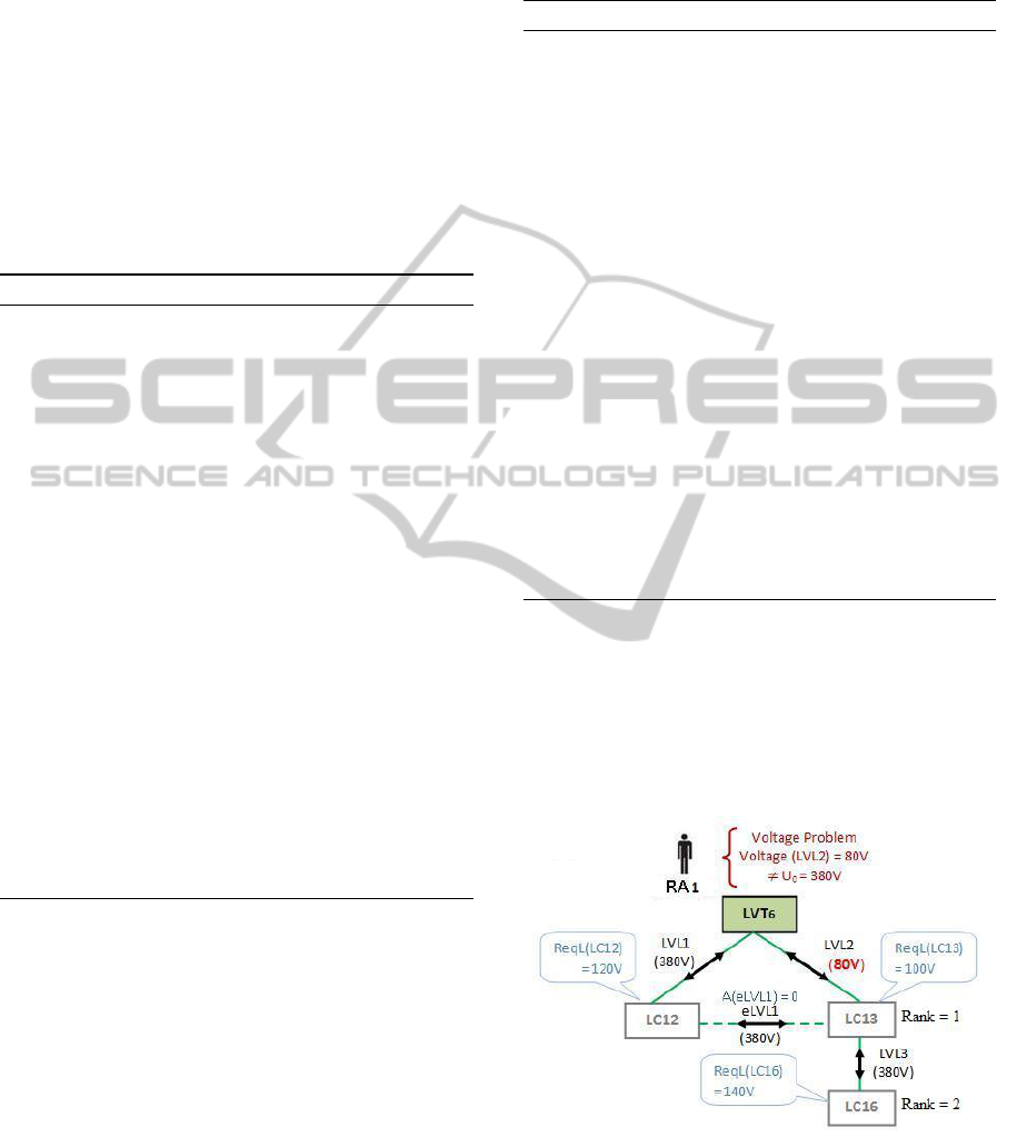
7.1 Local Fault Recovery
Let us consider the case where there is a problem
on the line LV L2 and let us suppose that the volt-
age value detected on LV L2 is equal to 80V 6= U
0
(Figure 2). This value involves an instability prob-
Figure 2: Detection of a voltage problem on LV L2.
lem on the concerned sub-grid. This voltage instabil-
ity is detected and identified by RA1, the RAgent as-
signed to the sub-grid supplied by LV T 6. RA1 reacts,
then, and isolate the fault by deactivating LV L2 (Fig-
ure 3). As a consequence to this deactivation, there
NewSolutionsforFaultDetectionsandDynamicRecoveriesofFlexiblePowerSmartGrids
375
is an emergence of faults F1 and F2 which are de-
tected, respectively, on LC13 and LC16. As defined
in section 4, F1 is dominant on F2. Hence, RA1
tries to resolve the dominant fault F1. For that, a
local solution is searched and RA1 looks for the ex-
istence of emergency lines in the supervised sub-grid.
Since, there is an emergency line (eLV L1) incoming
to LC13 and eLV L1 is able to, sufficiently, supply
LC13. RA1 executes this feasible solution and acti-
vates the emergency line eLV L1, which resolves the
problem. The detection and resolution CPUs, were,
respectively, equal to 1, 78s and 0,69s.
Figure 3: Problem Localization and Resolution.
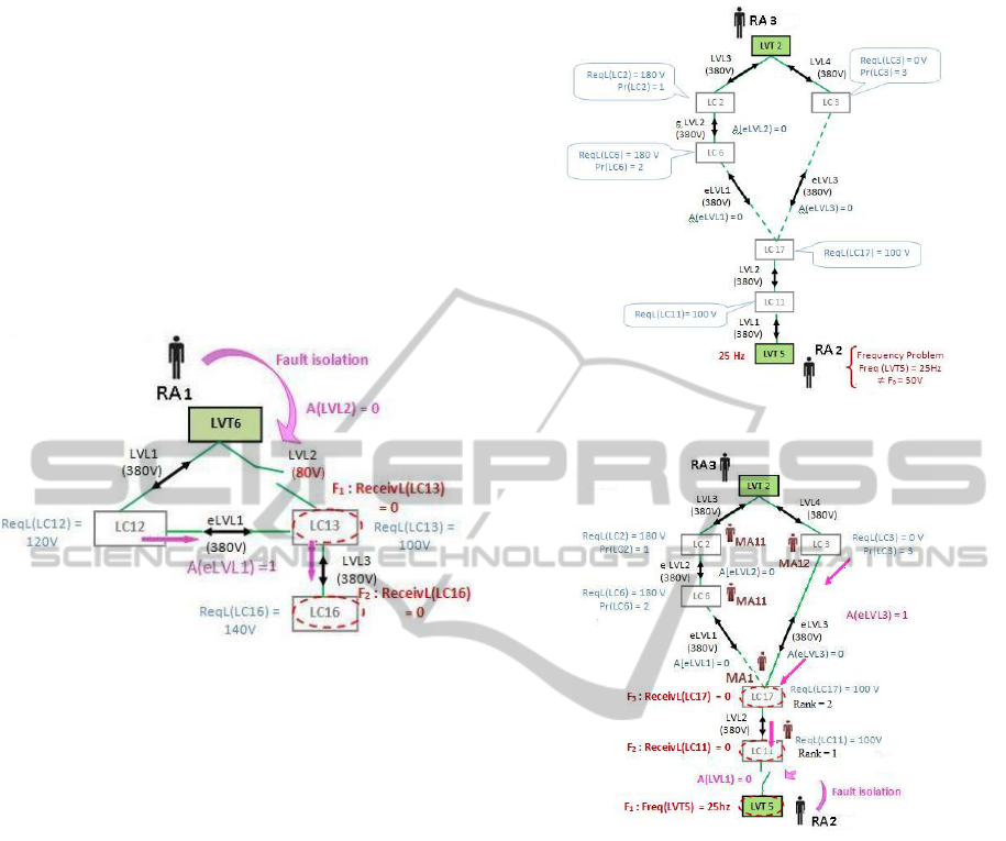
7.2 Distributed Fault Recovery
The second studied case is about a frequency problem
observed on the transformer LV T 5 (Figure 4). Let us
suppose that the frequency value detected on LV T 5,
at 11PM, is equal to 25hz 6= f
0
. The low voltage con-
sumers LC2, LC3 and LC6 represent, respectively, a
hospital, a university and a policy office having the
respective priorities 1, 3 and 2. At this time, LC3
does not require electricity while LC2 and LC6 re-
quire each one 180V . This instability of frequency
is detected by RA2, the agent assigned to the sub-grid
supplied by LV T 5. Then, RA2 isolates the fault by
deactivating LV L1. As a consequence, 3 faults; F
1
, F
2
and F
3
occur, respectively, on LV T 5, LC11 and LC17.
F
2
and F
3
are faults dominated by F
1
as illustrated by
Figure ??. As it is not possible to resolve F
1
since
LV T 5 requires a physical repairing, RA2 looks for re-
solving the dominated faults F
2
and F
3
. There is no
local solutions as there is no emergency lines belong-
ing to the sub grid. Then, RA2 requests the DBAgent
for searching a solution, stored in its central data base,
to the encountered problem. As this problem happens
for the first time over this sub grid, the DBAgent does
not return any solution. Thus, RA2 instantiates a MA-
gent MA1 on LC11 to search new solutions from other
Figure 4: Detection of a frequency problem on LV T 5.
Figure 5: Problem Localization and Resolution
sub grids connected to the supervised one. After vis-
iting LC17, MA1 is duplicated; the first clone MA11
visits LC6 and the second one MA12 visits LC3. Both
of them execute Algorithm 5 at each visited compo-
nent. The RAgent creator analyzes the results sent
by these two clones MA11 and MA12. For MA11, the
calculated remaining load is equal to 0 knowing that it
has not yet reached the end of its path (as LC6 has an
outgoing line). MA12, visiting LC3, reaches the end
of its path (as LC3 has 0 outgoing line) with remain-
ing load equal to 180V . At the next iteration, MA11
reaches the end of its path with a negative remaining
load equal to −180V which is invalid as it is negative.
The two responses are found on, respectively, 1,17s
and 1,09s. RA2 chooses the second solution provided
by MA12 as the first one is rejected; it consists of ac-
tivating eLV L2. There were only five messages ex-
changed between our deployed agents RA2 and MA1.
ICINCO2014-11thInternationalConferenceonInformaticsinControl,AutomationandRobotics
376

8 CONCLUSIONS
In this paper, we propose an agent-based approach to
resolve the faults in power systems which run accord-
ing to the following rules; (i) detect and localize the
problem,(ii) identify the problem by checking con-
straints, (iii) categorize the occurred faults and (iv)
choose the suitable strategy of search for solution (lo-
cal through RAgent or distributed through MAgent)
to accelerate the resolution. In future works, we are
interested in reducing the number of the deployed
agents by integrating a knowledge base in RAgents to
store local solutions in order to reduce the requesting
time. We are, also, interested in investigating multi-
ple and even concurrent faults at the same time. The
use of smart storage devices present, also, an interest-
ing issue for us as well as the failure rates to forecast
failures.
REFERENCES
Cai, Y., Chow, M. Y., Lu, W., and Li, L. (2010). Statisti-
cal feature selection from massive data in distribution
fault diagnosis. IEEE Transactions on Power Systems.
Calderaro, V., Hadjicostis, C. N., Piccolo, A., and Siano, P.
(2011). Failure identification in smart grids based on
petri net modeling. IEEE Transactions on Industrial
Electronics, pages 4613 – 4623.
Chen, J., Li, W., Lau, A., Cao, J., and Wang, K. (2010). Au-
tomated load curve data cleansing in power systems.
IEEE Transactions on Smart Grid.
Endriss, U., Maudet, N., Sadri, F., and Toni, F. (2004).
Logic-based agent communication protocols. In
In Advances in Agent Communication Languages.
Springer-Verlag.
He, M. and Zhang, J. (2010). Fault detection and localiza-
tion in smart grid: A probabilistic dependence graph
approach. In First IEEE International Conference on
Smart Grid Communications (SmartGridComm).
Lu, W., Besanger, Y., Zamai, E., and Radu, D. (2006).
Blackouts: Description, analysis and classification. In
in Proceedings of the 6th WSEAS International Con-
ference on Power Systems.
McArthur, S. D. J., Davidson, E. M., Catterson, V. M.,
Dimeas, A. L., Hatziargyriou, N. D., Ponci, F., and
Funabashi, T. (2007a). Multi-agent systems for
power engineering applications - part i: Concepts, ap-
proaches, and technical challenges. In IEEE Transac-
tions on Power Systems.
McArthur, S. D. J., Davidson, E. M., Catterson, V. M.,
Dimeas, A. L., Hatziargyriou, N. D., Ponci, F., and
Funabashi, T. (2007b). Multi-agent systems for power
engineering applications part ii: Technologies, stan-
dards, and tools for building multi-agent systems. In
IEEE Transactions on Power Systems.
Nagata, T. and Sasaki, H. (2002). A multi-agent approach
to power system restoration. In IEEE Transactions on
Power Systems.
Pipattanasomporn, M., Feroze, H., and Rahman, S. (2009).
Multi-agent systems in a distributed smart grid: De-
sign and implementation. In IEEE/PES Power Sys-
tems Conference and Exposition, Adv. Res. Inst., Vir-
ginia Tech, Arlington, VA.
Rahman, S., Pipattanasomporn, M., and Teklu, Y. (2007).
Intelligent distributed autonomous power systems
(idaps). In IEEE Power Engineering Society General
Meeting, Adv. Res. Inst. of Virginia Tech, Arlington,
VA.
Rohbogner, G., Fey, S., Hahnel, U. J. J., Benoit, P., and
Wille-Haussmann, B. (2012). What the term agent
stands for in the smart grid definition of agents and
multi-agent systems from an engineer
´
s perspective. In
Federated Conference on Computer Science and In-
formation Systems (FedCSIS).
Russell, B. D. and Benner, C. L. (2010). Intelligent systems
for improved reliability and failure diagnosis in distri-
bution systems. IEEE Transactions on Smart Grid.
Tate, J. and Overbye, T. (2008). Line outage detection using
phasor angle measurements. IEEE Transactions on
Power Systems.
Tate, J. and Overbye, T. (2009). Double line outage de-
tection using phasor angle measurements. In IEEE
Transaction on Power and Energy Society General
Meeting.
Vyatkin, V., Zhabelova, G., Higgins, N., Schwarz, K., and
Nair, N. C. (2010a). Towards intelligent smart grid
devices with iec 61850 interoperability and iec 61499
open control architecture. In IEEE Transmission and
Distribution Conference and Exposition.
Vyatkin, V., Zhabelova, G., Higgins, N., Ulieru, M.,
Schwarz, K., and Nair, N. C. (2010b). Standards-
enabled smart grid for the future energy web. In Inno-
vative Smart Grid Technologies.
Vyatkin, V., Zhabelova, G., Ulieru, M., and McComas, D.
(2010c). Toward digital ecologies: Intelligent agent
networks controlling interdependent infrastructures.
In First IEEE International Conference on Smart Grid
Communications (SmartGridComm).
Zhabelova, G. and Vyatkin, V. (2012). Multiagent
smart grid automation architecture based on iec
61850/61499 intelligent logical nodes. In IEEE Trans-
actions on Industrial Electronics.
NewSolutionsforFaultDetectionsandDynamicRecoveriesofFlexiblePowerSmartGrids
377
