
Development of Micro-channel Arrays
for Peripheral Nerve Recording
David J. Edell
1
, Ronald R. Riso
2
and Hugh Herr
2
1
Innersea Technology Inc., 1 DeAngelo Drive, Bedford, MA., U.S.A.
2
Biomechatronics Dept., Media Lab, Massachusetts Institute of Technology, 75 Amherst St., Cambridge, MA., U.S.A.
Keywords: Peripheral Nerve Interface, Micro-Channel Array, Prosthesis Control, Prosthesis Sensory.
Abstract: MicroTube Array (MTA) technology was developed to create an axon regeneration interface for exchanging
motor and sensory data with residual nerves. Future clinical application will include sensory-motor
transducers for individuals with limb amputation. In this pilot study, a small matrix (9) of MTAs 1, 3 and
5mm long with either 99um, 200um or 287um diameter MicroTubes (MTs) filling nerve cuffs of 3mm in
diameter were implanted in tibial nerve of NZW rabbits and histologically evaluated after more than 6
months post-op. Full regeneration was observed in all 3 lengths for 287um MTAs, and for all three
diameters of MTs with 1mm length. The remaining implants were mechanically dislodged during the
healing phase. A second implant set was designed to include 12 platinum-iridium wire electrodes direct
wired to a percutaneous connector. Successful recordings of useful amplitudes were observed during reflex
righting behaviour for over 2 years before the anticipated wire breakage ended the experiments.
1 INTRODUCTION
Recent advances in the design of upper and lower
extremity prosthetic limbs has underscored the need
to provide more effective means for amputees to
control these prostheses as well as to provide
sensation from these devices. It is widely
appreciated that these goals could best be met by
establishing a permanent electrical interface with the
trunk nerves in an amputee’s residual limb (Mannard
et al. 1974; Edell 1986; Riso 1999), however the
development of the technology to achieve this has
been elusive. Among the approaches that have been
advocated and continue to be researched are: diverse
designs of nerve cuffs (Loeb and Peck 1996; Naples
et al. 1988; Walter et al. 1997; Grill and Mortimer
1998; Hoffer and Kallesoe 2000; Schuettler and
Stieglitz 2000), intrafasicularly placed fine wire
(Lefurge et al. 1991) and conductive polymer
filaments (McNaughton and Horch 1996; Lawrence
et al. 2002; Lawrence et al. 2004; Boretius et al.
2010), transverse penetrating arrays of
microfabricated needle electrodes [e.g. Utah “Slant
Array” (Clark et al. 2011; Wark et al. 2013)] and
“sieve” (Kovacs et al. 1992; Bradly et al. 1997;
Wallman et al. 2001; Lago et al. 2005) styled
devices. While progress continues to be made (see
for example Tan et al. 2014), none of these device
designs has been shown to completely meet the
needs of the prosthesis application in terms of
numbers of independent recording channels for
obtaining motor commands, provision for activating
discrete sensory afferents for feedback of tactile and
proprioceptive events, or device longevity (although
cuff designs have been successfully deployed for
other neuroprosthesis applications such as bowel and
bladder control (Creasey et al. 2001) or FES based
standing and walking for paraplegia (Schiefer et al.
2013).
The most useful device for an individual with
amputation would provide sufficient information
exchange between the nerve and prosthesis to enable
return of complete and natural sensorimotor
function. One approach is to embed the distal end of
the residual nerve within a nerve cuff that contains
properly designed and constructed MicroTube
Arrays (MTAs). MTAs are small diameter Micro
Tubes (MTs) that each contain neural recording and
activation functionality for use in motor control and
sensation. Under appropriate conditions, axons in all
severed nerves will regenerate into and through
small openings in MT devices.
In 1974, it was known that amphibian peripheral
5
J. Edell D., R. Riso R. and Herr H..
Development of Micro-channel Arrays for Peripheral Nerve Recording.
DOI: 10.5220/0005091500050012
In Proceedings of the 2nd International Congress on Neurotechnology, Electronics and Informatics (NEUROTECHNIX-2014), pages 5-12
ISBN: 978-989-758-056-7
Copyright
c
2014 SCITEPRESS (Science and Technology Publications, Lda.)
nerves would regenerate through small holes in
implant structures from the work of Mannard and
Stein (1974; Stein et al. 1975), but that approach was
not successful when applied to mammals. In 1980
Edell showed that with biocompatible materials and
design, the regeneration approach would work in
rabbit peripheral nerves (Edell 1980; Edell et al.
1982). However, the selectivity of the recordings
was limited by the open environment about the
electrodes. In 1977, Loeb et al. (1977) published a
method for isolating small groups of axons and
improving signals in peripheral nerves by having
them regenerate through MicroTubes, but was
unsuccessful in making it work. The theory was
sound - small diameter tubes increase signal
amplitudes by increasing the effective extracellular
resistance (Fitzgerald et al. 2008). However, the
choice of dimensions (~10x15um) for the tubes was
perhaps smaller than needed for the required support
cells, collagen and capillaries, and the materials’
surfaces may have triggered tissue micro-
incompatibility.
This paper describes previously unpublished
studies (DARPA project, 2006) demonstrating that
MTAs can be made to work in rabbit peripheral
nerves. Results are reported concerning an initial
study that surveyed the effects of MT diameter and
MT length on the ability of nerve fibers to grow into
such devices and provide stabile recordable, multi-
channel neural activity for use in prosthesis control.
Robust regeneration into 100um diameter MTs was
documented, the smallest diameter tested.
Histological evidence suggests that MTs as small as
25um may be possible if properly designed. Within
each MT there must be room for collagen, Schwann
cells, and capillaries for mechanical, axonal, and
metabolic support. These early findings have been
corroborated in recent studies in other laboratories
where successful neural regeneration has been
reported (in rodents) into devices having channel
sizes with cross sections of 100um x100um (Lacour
et al. 2009) or as small as 70um x 20um rectangles
(Stoyanov et al. 2013) and this results in the
subdivision of a composite nerve into mini-fascicles
which may enhance the separability of targeted
nerve fibers by functional type.
2 METHODS
2.1 MicroTube Array Device
Fabrication
MTAs were constructed within a Class 100
cleanroom from micro-polyimide tubing (Micro-
Lumen) aggregated together within 2.5mm ID
polyimide tubing. The interior diameters of the MTs
were either 287, 203 or 99um (Fig 1). The bundled
tubing was sliced transversely to produce micro-
channel arrays having defined lengths of 1, 2 and
3mm.
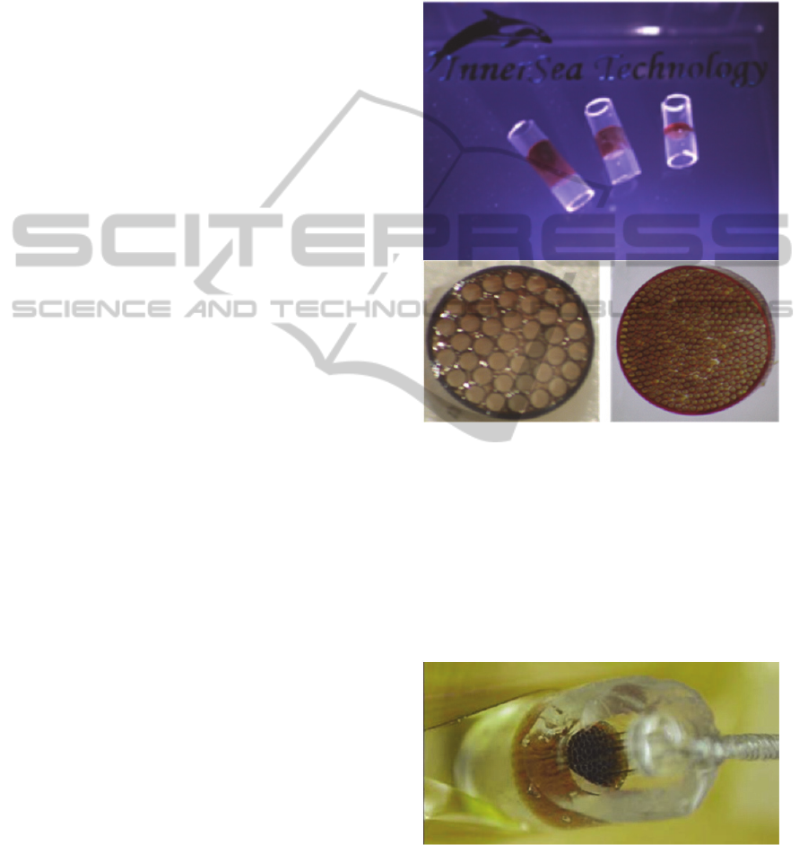
Figure 1: Top – photograph showing the microchannel
arrays that were constructed using three different lengths
of MTs. MTAs can be seen as the darken areas within the
nerve cuffs); Lower - Photographs showing the cross
sections of arrays that were comprized of the largest
diameter tubes (287um dia.) and the smallest diameter
tubes (99um dia.) used in this study. These arrays
contained approximately 40 and 400 MTs, respectively.
2.2 Incorporation of Recording
Electrodes into MicroTube Arrays
Figure 2: Magnified view of 3mm long, 203um diameter
MicroTubes (brown) with 50um diameter insulated
iridium microelectrode shafts placed halfway into 12 of
the MicroTubes. The portal visible at the center of the
picture is the exit port required for axon growth. Reference
electrode coils and nerve cuffs were added to both the
entry and exit chambers after this photo was obtained).
NEUROTECHNIX2014-InternationalCongressonNeurotechnology,ElectronicsandInformatics
6
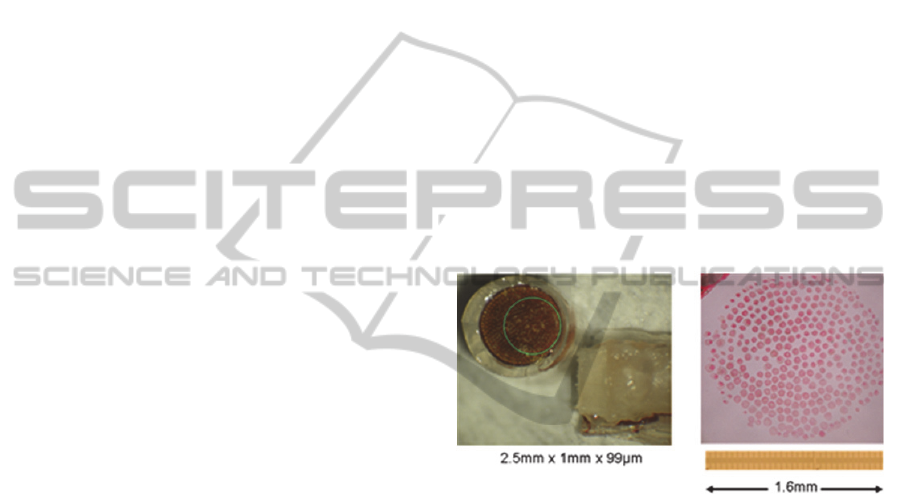
Fig. 2 shows a photograph of an assembled MTA
nerve interface device in which 12 of the MTs are
instrumented for neural recording and/or
stimulation.
2.3 Experimental Design for in-Vivo
Studies
The first part of this pilot study was aimed at
determining the extent to which channel size (i.e.
cross sectional area) would influence the ability of
nerve fibers from a newly transected nerve to enter
and grow through the channels. A second objective
was to determine any effects of the channel length
on neural ingrowth. To address these issues, nine
New Zealand White rabbits (2.4-3kg) were
implanted with a nerve interface device from a
matrix of 9 devices representing combinations of the
three MT sizes (287, 203 and 99um dia.) and three
channel lengths (1, 3 and 5mm).
As this study was intended only as an initial
survey, only one animal could be assigned to each of
the nine permutations of channel size and channel
length. All of the animal studies were reviewed and
approved by the MIT- IACUC. With the animal
fully anesthetized and using sterile technique, the
sciatic nerve on one leg was exposed just proximal
to the knee, and the tibial nerve component was
isolated and transected taking care not to injure the
peroneal and sural nerve components. The proximal
end of the isolated tibial nerve was inserted into the
MTA device and secured using microsutures applied
through the epineurium. The distal segment of the
transected nerve was then inserted into the distal
opening of the nerve interface.
While this animal model is not a full amputation
model, it was selected because it allows for
monitoring of the progress of the nerve regeneration.
The experimenter can readily observe when the
regenerating nerve has traversed the nerve interface
device and reconnected to the distal nerve target
tissues. Thus, any return of ankle extensor function,
either volitional or reflexive, denotes successful
motor nerve regeneration through the device.
Sensory nerve regeneration can be accessed by
applying toe pinch and noting a return of flexor
withdrawal of the limb.
Activity can be conveniently elicited by placing
the animal prone on a table and gently rolling the
head and shoulders from side to side. Leg extension
will ensue as the animal acts to maintain balance. A
second technique that was used to evoke activity in
the ankle extensor muscle (and thus tibial nerve
activation) involves the “drop reflex” whereby the
animal is held in the air and then lowered towards
the table so that the foot extends in anticipation of
falling.
3 RESULTS
3.1 Assessment of Nerve Regeneration
After the tibial nerve regeneration was relatively
stable as judged by the return of voluntary and reflex
control of ankle extension function, each animal was
euthanized and the devices retrieved for histological
examination. Figure 3 shows the results seen with
one of the implants (99um channels and 1mm
length). The tissue was fixed in formalin and then
the attached nerve was pulled out of the interface
device, embedded in paraffin and stained. Not all of
the fine micro-fascicles would slide out of the
MicroTubes. However, for the most part, the micro-
channel array pattern is evident.
Figure 3: Left – Photograph of explanted 1mm long and
99um diameter MicroTube array assembly after
regenerated peripheral nerve was removed. Green circle
depicts the region from which the nerve mini-fascicles
shown at the right were withdrawn. Right – Micrograph
depicting the core of neural tissue that had grown through
the micro-channel nerve interface.
Among the 9 implanted animals there were three
mechanical failures most likely caused by fixation of
the implants by connective tissue (which occurs
rapidly) in a location that was not ideal
mechanically. Straightening of the leg, perhaps
when ear scratching, or during cage changes during
the early healing phases could have generated suffic-
ient stress on the interface to result in the nerve
pulling out. In one instance (5mm long, 203um
diameter array), partial regeneration occurred
through a collapsed cuff where the distal nerve had
been pulled out but the sutures held. The sutures
collapsed the cuff so only a small opening was
available for nerve regeneration to traverse on the
distal side. There was good histology obtained from
DevelopmentofMicro-channelArraysforPeripheralNerveRecording
7
the small subset of MTs that could support
regeneration in the limited space.
Most of the MTs were filled with myelinated and
(probably) non-myelinated axons, collagen and
fibroblasts, and most importantly, capillaries (see
summary in Table 1).
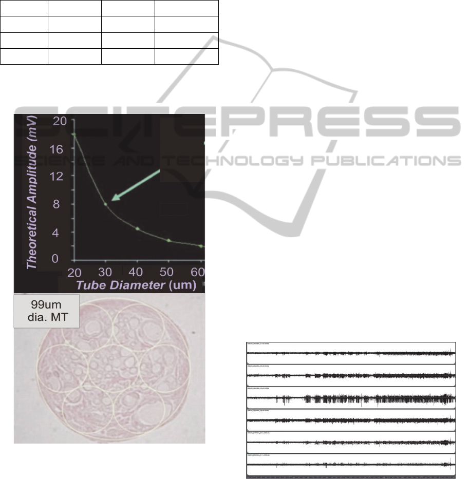
Table 1: Matrix of MT diameters and lengths studied.
Length\Dia 287 µm 203 µm 99 µm
1 mm Regeneration Regeneration Regeneration
3 mm Regeneration Pulled Out? Pulled Out?
5 mm Regeneration Partial* Pulled Out?
3.2 Speculation regarding Minimal
Micro-Channel Sizes
Figure 4: Upper – Theoretical graph showing the effect of
micro-channel diameter for a 3mm long MT vs. the
expected signal amplitude recordable from a single node
of Ranvier positioned at the center of a MT with either a
larger or smaller diameter. Lower – micrograph showing
regenerated neural tissue that was removed from one MT
of an explanted 3mm long and 99um dia. MTA assembly.
Capillaries can be seen in all “sampled” regions delineated
by the 33um dia. superimposed circles.
Figure 4 (upper) shows a graph of the theoretical
signal amplitude that could be recorded from one
node of Ranvier that is centered in 3mm long MTs
of different diameters. The micrograph (Fig. 4
lower) showing the neural tissue that regenerated
into a 99um dia. tube, was overlayed with small
(yellow) circles having 33um dia., and it can be seen
that there is a sufficient density of axons, capillaries
and support cells within each drawn circle to suggest
that regeneration would be successful for MT
diameters of this small size (33um). Notably, if this
regeneration were successful, then the use of small
MTs on the order of the 33um dia. could be expected
to afford axon signals in the range of 8mV as
indicated by the green arrow in the figure.
3.3 Recordings of Neural Activity
Based on results from the regeneration studies with
the 203um diameter x 3mm long MTA, and the fact
that the effects of the presence of 50um wires within
the tubes was unknown, we decided to use these
intermediate sized tubes as the basis for developing
the neural interface array that incorporated integral
electrodes.
Three devices were constructed and implanted.
Each of the implants was successful. The first two
animals showed signs of regaining muscle function,
and yielded good recordings after 6 weeks. The
third animal showed promising recordings after 4
weeks, but shortly thereafter the percutaneous
connector that was used to access the electrodes
failed. Useful recordings were able to be obtained
throughout the 7 months post implantation that the
animals were studied. Examples of recorded neural
activity from the first animal are shown in Figs. 5, 6
and 7.
Figure 5: Example waveforms from rabbit R06015 approx.
3 months post-implantation. While immature, axons were
beginning to exhibit robust responses to the righting reflex
(~6-13s. middle time section of graph) and steady
resistance to manipulation (~13.5s-end). (Max ampl. ~
180uV).
NEUROTECHNIX2014-InternationalCongressonNeurotechnology,ElectronicsandInformatics
8
For this animal, six of the eleven recording channels
yielded high quality signals (Fig. 5) while four
channels produced lower amplitude signals and one
channel had a failed lead at the time of implantation.
The capacity for selective channel recording was
clearly evident as there are frequent occurrences of
activity present on one channel that does not occur
on neighboring channels. In addition to
demonstrating freedom from channel crosstalk, this
shows that the recorded activity originates with
axons contained within each specific tube and is not
due to contaminating artifacts such as EMG from
muscle tissue that’s surrounds the implant (since
such activity would be expected to contaminate all
of the channels simultaneously if not excluded by
the differential recording instrumentation). There is
also a considerable amount of nerve activity that
occurs approximately at the same time among
different channels (Fig. 5). This is due to recruitment
of motor units or afferent feedback that is synergistic
since the neural waveforms are not coincident as
would be expected if they were from the same
neurons.
The independence of the recording channels in
this same animal is more readily apparent in Fig. 6
which shows two different epochs of nerve activity
(left and right columns) that were recorded
simultaneously using electrodes #3 and #8 (compare
upper vs. lower panels).
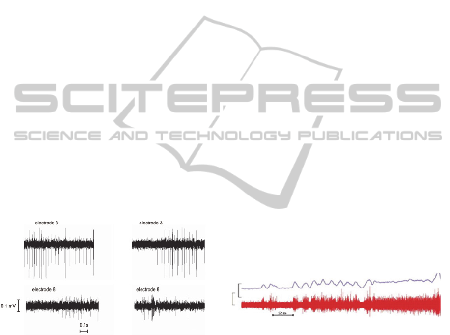
Figure 6: Example of recorded neural activity from animal
R06029 electrodes 3 and 8. LEFT - simultaneous
recordings showing distinct differences in activity levels
and type. RIGHT - recordings from another episode of
activity again showing little correlation other than similar
timing of general heightened activity. Data acquired 6
weeks post-implant.
3.4 Qualities of the Recorded Axons
from Regenerated, Maturing Axons
The recorded nerve activity showed a wide range of
action potential amplitudes as well as spike
durations. It isn’t known at this point why some
channels yielded higher amplitude recordings than
others. We can offer several speculations to explain
these effects: 1) Possibly the amplitude disparity is
due to the nerve fibers not being fully regenerated in
one channel verses another, as newly regenerated
fibers are known to have smaller diameters, and
thinner myelination than more mature fibers and
thus have lower amplitude action potentials. 2) With
regard to the range of action potential durations -
The design of the microtube constricts the small
axonal currents so that large signal amplitudes are
recorded from non-myelinated fibers as well as
myelinated fibers though the time course of the
waveforms are markedly different. It is worth
noting that the ability to record from non-myelinated
fibers may be desirable for neurophysiology studies
as small caliber autonomic fibers are normally
difficult to record. The small diameters, thin myelin,
and closely spaced nodes of the recently regenerated
axons are associated with slow nerve conduction
velocities and the action potentials from small fibers
(and particularly from unmyelinated immature fibers
or autonomic nerve fibers) tend to be of long
duration. 3) Some of the largest recorded activity
may represent compound action potentials formed
from the superposition of quasi-simultaneous nerve
discharges within the tube structures. 4) There is a
wide distribution of fiber diameters in any peripheral
nerve so that even a normal nerve has a wide
distribution of amplitudes and action potential
duration due to the fiber diameter distributions.
3.5
Utility of Combined Activity from
Different Channels
Figure 7: Composite signal from combining channels
1,2,3,9,10,11 yields a more predicable response than
single channels due to the effective increase in motor unit
pool being recorded. Note pulsed responses due to
rhythmic righting reflex and relatively steady amplitude
due to continuous force on leg, followed by relatively
vigorous response at end. Amplitude bar: lower trace
approximately 85uV; upper trace was a smoothed/rectified
image of lower trace where the amplitude bar is about
8.5uV.
There have been several instances where
recordings of ‘whole nerve’ have been useful for
neuro-prosthetic devices (Haugland and Sinkjaer
1999; Sinkjaer et al. 1999; Riso and Slot 1996).
Using the microtube array it is possible to select
various combinations of channels to create the
DevelopmentofMicro-channelArraysforPeripheralNerveRecording
9

highest quality composite signals. Fig. 7 shows an
example of combining channels 1,2,3,9,10, and 11
from one experiment to achieve such a composite
signal to
better represent the intended contraction of a
particular tibial n. innervated muscle or group of
muscles than each waveform alone.
An estimate of the composite signal intensity
(solid line) is shown above the raw neural
waveforms. With smaller tubes, more ‘muscle
specific’ reconstruction of the efferent activity could
be achieved. In addition, tubes that contained
afferent nerve fibers could be designated for
stimulation for cutaneous or proprioceptive
sensation. Since axons tend to aggregate by function
in peripheral nerves, this approach should be robust.
4 DISCUSSION AND
CONCLUSIONS
4.1 Choice of Animal Model
Rabbits have long been accepted as adequate models
for peripheral nerve repair work in humans. Rats
and lower animals, particularly amphibians,
regenerate more robustly than rabbits and higher
animals, and thus, the results obtained with those
preparations are not as readily extrapolated to the
human condition. Because the studies presented
herein were performed using an animal model in
which the nerve interface served as a bridge between
the transected ends of the tibial nerve, for
experimental expediency, it might be argued that the
successful regeneration of the nerve into the device
may depend strongly on the ability of the proximal
nerve to reconnect to the distal portion of the
transected nerve and thus may not be applicable for
interfacing to the truncated nerves in the amputee’s
residual limb.
At issue here is not whether the transected nerve
will regenerate into a MTA. So long as the distal end
of the MTA remains sufficiently open, the nerve
fibers will exit the device and form into a
disorganize mass as a neuroma. It is generally best,
however, to avoid the occurrence of a neuroma
because neuroma tissue frequently is overly
sensitive to mechanical stimulation. This can result
in painful sensations unless specific tactics are used
to shield the neuroma from such stimulation.
One solution to prevent the formation of a
neuroma in the absence of the distal nerve segment
for attachment, is to provide small pieces of target
tissue (e.g. muscle or skin) at the distal exit of the
nerve interface. This target tissue allows the
regenerated nerve fibers to terminate onto
appropriate end organs and has a stabilizing effect
on the nerve. A possible contra-indication with
applying this strategy, however, is that the receptors
present in the target tissue may generate activity in
the connected nerve that could conflict with the
intended nerve recording or stimulation paradigm.
Further research in this area is warranted.
4.2 Importance of Channel Size
Smaller (more narrow) channels favor improved
separability of axons so that efferent fibers to
muscles that normally would control different
functions don’t co-mingle within the same channel.
Additionally, segregation of the motor units
associated with any given muscle into smaller
groups allows for finer resolution for the derived
control signal. Where desired, perhaps to achieve a
more robust control signal, the activity of those
channels could always be recombined. Furthermore
as previously stated, the recorded signal amplitude is
larger for smaller diameter channels.
With regard to electrical stimulation to provide
sensory feedback, it would be best to be able to
selectively activate afferent fibers that shared a
common modality and region of referred sensation.
While there is some evidence from
microneurography studies in man (Stoyanov et al.
2013; Ochoa and Torebjörk 1983), that suggests
grouping of sensory axons in peripheral nerves by
modality, and end receptor location, presently too
little is known about the extent of such grouping as
they course, for example, from the brachial plexus,
down the arm, and to the wrist and fingers to be able
to suggest optimal channel sizes.
Ultimately, selection of an “optimal” channel
size might depend on the intended application for
the nerve interface and the particular morphology of
the targeted nerve. The best strategy currently
would seem to be to develop a modular system that
would be scalable and adaptable to accommodate
different size nerves and different locations within
the amputee’s residual limb. Large trunk nerves are
intrinsically divided into small fascicles by
perineurium, and within the small fascicles, axons
aggregate mostly by function. As the axons near
their targets, they further segregate into individual
fascicles before exiting the nerve trunk. With a
scalable system, the level of amputation would not
present significant difficulty as it is simple to deploy
individual interface devices to each of the divided
NEUROTECHNIX2014-InternationalCongressonNeurotechnology,ElectronicsandInformatics
10

nerve fascicles. Most fascicles are 0.5-2mm
diameter. Some fascicles are larger, but can easily
be divided as needed to accommodate a standard
MTA interface sub-unit of perhaps 2.5mm diameter.
An additional benefit of employing the micro-
channel approach to nerve interfacing is that the
same micro-channel could be used for both motor
and sensory functions as desired. This feature may
be particularly important for groups of axons
destined for a muscle, as motor nerves carry a great
deal of sensory information about the muscle target.
Once the physiological function of each micro-
fascicle is determined, information can be combined
as appropriate.
4.3 Design Considerations for MTA
Devices
It should be noted that in spite of its use in this pilot
work, polyimide is NOT a suitable long term
implant material – it undergoes slow hydrolytic
degradation and will over time fail as an insulator.
Further, the wall thickness is far too great for use in
a good clinical device. The open area occluded by
wall thickness can completely prevent regeneration.
While in these simple single fascicle experiments the
open area of the devices can be kept to at least the
open area of the fascicle, in a practical device for
human shoulder, arm or leg amputation applications
might require many of these devices and result in
unnecessary bulk. A better solution would be to use
silicon dioxide or titanium dioxide MTs fabricated
on low-power integrated circuit substrates. Such
substrates would assist to mechanically stabilize the
nerve interface, and the integrated electronics could
be insulated reliably (Edell 2004) to survive
implantation for decades with minimal bulk.
ACKNOWLEDGEMENTS
The authors would like to acknowledge the
assistance of the Huntington Medical Research
Laboratory for providing the Platinum-Iridium
microwire electrodes that were used in developing
the recording aspect of the nerve interface design.
This research was supported by: DARPA grant
DSO N66001-05-C-8030, “Peripheral Nerve
Interface Technology for Bidirectional Neural
Communication” H. Herr-PI, with sub-contract to
InnerSea Tech. Inc.
REFERENCES
Boretius T, Badia J, Pascual-Font A, Schuettler M,
Navarro X, Yoshida K and Stieglitz T 2010, ‘A
transverse intrafascicular multichannel electrode
(TIME) to interface with the peripheral nerve’,
Biosens. Bioelectron., vol. 26, pp. 62–69.
Bradley RM, Cao X, Akin T and Najafi K 1997, ’Long
term chronic recordings from peripheral sensory fibers
using a sieve electrode array’, J. Neurosci. Methods,
1997, vol. 73, no. 2, pp. 177-186.
Clark GA, Ledbetter NM, Warren DJ and Harrison RR
2011, ‘Recording sensory and motor information from
peripheral nerves with Utah Slanted Electrode Arrays’,
in Proceedings of the 33rd Annual International
Conference of the IEEE Engineering in Medicine and
Biology Society, Aug 30-Sep 3, Boston pp. 4641-4644.
Creasey GH, Grill W, Korsten M, Sang HU, Betz R.
Anderson R and Walter J 2001, ‘An implantable
neuroprosthesis for restoring bladder and bowel
control to patients with spinal cord injuries: A
multicenter trial,’ Arch. of Physical Med. and Rehab.
vol. 82, no. 11, pp. 1512–1519.
Edell DJ 2004 ‘Insulating Biomaterials’, Chapter 3.2, in
Neuro-prosthetics Theory and Practice, eds KW
Horch and GS Dhillon, World Scientific Publishing
Co., pp. 517-579.
Edell DJ 1980, Dissertation: ‘Development of a Chronic
Neuroelectric Interface’, University of California.
Edell DJ, Churchill JN and Gourley IM 1982, ‘Biocom-
patibility of a silicon based peripheral nerve
electrode”, Biomat. Med. Dev. Art. Org., vol. 10, pp.
103-122.
Edell DJ 1986 ‘A peripheral neural information transducer
for amputees: long- term multichannel recordings from
rabbit peripheral nerves’, IEEE Trans. Biomed. Eng.,
vol. 33, pp. 203-214.
Fitzgerald JJ, Lacour SP, McMahon SB and Fawcett JW
2008 ’Microchannels as axonal amplifiers’, IEEE
Transactions on Biomedical Engineering , vol. 55, no.
3, pp. 1136-1146.
Grill WM and Mortimer JT 1998,’Stability of the input
output properties of chronically implanted multiple
contact nerve cuff stimulating electrodes’, vol. 6, no.4,
pp. 364-373.
Haugland M and Sinkjær T, ‘Interfacing the body's own
sensing receptors into neural prosthesis devices,’
Technology and Health Care, vol. 7, no. 6, pp.393-
399, 1999.
Hoffer JA and Kallesoe K 2000, ‘How to use nerve cuffs
to stimulate, record or modulate neural activity’.
Chapter 5, In: Neural Prostheses for Restoration of
Sensory and Motor Function, K.A. Moxon and J.K.
Chapin Eds., CRC Press, pp. 139-175.
Kovacs GTA, Storment CW and Rosen JM 1992,
‘Regeneration microelectrode array for peripheral
nerve recording and stimulation’, IEEE Trans.
Biomed. Eng., vol. 39, pp. 893-902.
Lacour SP, Fitzgerald JJ, Lago N, Tarte E, McMahon S
and Fawcett J 2009, ‘Long Micro-Channel Electrode
DevelopmentofMicro-channelArraysforPeripheralNerveRecording
11

Arrays: A Novel Type of Regenerative Peripheral
Nerve Interface’, IEEE Trans. on Neural Systems and
Rehab. Eng., vol. 17, no.5, pp. 464-460.
Lago N, Ceballos D, Rodríguez FJ, Stieglitz T, and
Navarro X 2005, ‘Long term assessment of axonal
regeneration through polyimide regenerative
electrodes to interface the peripheral nerve’,
Biomaterials, 2005, vol. 26, no.14, pp. 2021-2031.
Lawrence SM, Larsen JO, Horch KW, Riso R, and
Sinkjear T, 2002, ‘Long-Term biocompatibility of
implanted polymer-based intra-fascicular electrodes,’
J. Biomed. Mat. Res., 2002, vol. 63, pp. 501-506.
Lawrence SM, Dhillon GS, Jensen W, Yoshida K and
Horch KW 2004, ‘Acute peripheral nerve recording
characteristics of polymer-based longitudinal
intrafascicular electrodes’, IEEE Trans. Neural. Syst.
Rehabil. Eng., vol. 12, no. 3, pp. 345-348.
Lefurge T, Goodall E, Horch K, Stensaas L and
Schoenberg A 1991, ‘Chronically implanted
intrafascicular recording electrodes’, Annals of
Biomedical Engineering, vol. 19, no. 2, pp. 197-207.
Loeb GE, Marks WB and Beatty PG 1977, ‘Analysis and
microelectronic design of tubular electrode arrays
intended for chronic, multiple single-unit recording
from captured nerve fibres’, Med. Biol. Eng. Comput.,
1977, vol. 15, pp. 195-201.
Loeb GE and Peck RA 1996, ‘Cuff electrodes for chronic
stimulation and recording of peripheral nerve activity’,
J Neurosci Methods, vol. 64, no. 1, pp. 95-103.
Mannard A, Stein RB and Charles D 1974, ‘Regeneration
electrode units: implants for recording from single
peripheral nerve fibers in freely moving animals’,
Science, vol. 183, no. 124, pp. 547-549.
McNaughton TG and Horch KW 1996 ‘Metallized
polymer fibers as leadwires and intrafascicular
microelectrodes’, J. Neurosci. Methods, vol. 70, no.1,
pp. 103-110.
Milkman, R 1998, 'The new American workplace:high
road or low road?' in Workplaces of the future, eds P
Thompson and C Warhurst, Macmillan Press, London,
pp. 22-34.
Naples GG, Mortimer JT, Scheiner A, and Sweeney JD
1988, ‘A spiral nerve cuff electrode for peripheral
nerve stimulation’, IEEE Trans. Biomed. Eng., vol. 35,
pp. 905-916.
Ochoa J and Torebjörk E 1983, ‘Sensations evoked by
intraneural micro-stimulation of single mechano-
receptor units innervating the human hand’, J. Physiol.
vol. 342, pp. 633-654.
Ochoa J and Torebjörk E 1989, ‘Sensations evoked by
intraneural micro-stimulation of C nociceptor fibres in
human skin nerves,’ J Physiol. vol. 415, pp. 583-599.
Riso RR and Slot PJ 1996, ‘Characterization of the ENG
activity from a digital nerve for feedback control in
grasp neuroprostheses’, in Neuroprosthetics: from
Basic Research to Clinical Applications. eds A
Pedotti, M Ferrarin, J Quintern, R Riener, Springer,
Berlin, pp. 345-357.
Riso RR, 1999, ‘Strategies for providing upper extremity
amputees with tactile and hand position feedback-
moving closer to the bionic arm’, Technology in
Health Care, vol. 7, no. 6, pp. 401-409.
Schiefer MA, Freeberg M, Pinault GJ, Anderson J, Hoyen
H, Tyler DJ and Triolo RJ 2013,‘Selective activation
of the human tibial and common peroneal nerves with
a flat interface nerve electrode’, J Neural Eng., vol.
10, no.5, 056006. PubMed PMID: 23918148; PubMed
Central PMCID: PMC3809099.
Schuettler M and Stieglitz T 2000, ‘18polar hybrid cuff
electrodes for stimulation of peripheral nerves’, in:
Proceedings of the 5th Annual Conference of the
International Functional Electrical Stimulation
Society, Alborg, Denmark, pp. 265-268.
Sinkjær T, Haugland M, Struijk J, and Riso RR 1999,
‘Long-term cuff electrode recordings from peripheral
nerves in animals and humans’, in Modern Techniques
in Neuroscience Research. eds U Windhorst and H
Johansson, Springer, Berlin, pp. 787-802.
Stein RB, Charles D, Davis L, Jhamandas J, Mannard A,
and Nichols TR 1975 ‘Principles underlying new
methods for chronic neural recording.’ Can J Neurol
Sci, vol. 2, pp. 235-244.
Stoyanov II, van Wezel RJ and Rutten WL 2013, ‘In vivo
testing of a 3D bifurcating microchannel scaffold
inducing separation of regenerating axon bundles in
peripheral nerves’, J Neural Eng., vol. 10, no. 6,
066018 (13pp)
Tan D, Schiefer M, Keith MW, Anderson R and Tyler DJ
2013, ‘Stability and selectivity of a chronic, multi-
contact cuff electrode for sensory stimulation in a
human amputee’, in Proceedings of the 6
th
International Conference on Neural Engineering
(NER IEEE/EMBS), Nov 6-8, San Diego, CA, pp. 859-
862.
Wallman L, Zhang Y, Laurell T and Danielsen N 2001,
‘The geometric design of micromachined silicon sieve
electrodes influences functional nerve regeneration’,
Biomaterials, 2001. vol. 22, no. 10, pp. 1187-1193.
Walter JS, Griffith P, Sweeney J, Scarpine V, Bidnar M,
McLane J and Robinson C 1997, ‘Multielectrode
nerve cuff stimulation of the median nerve produces
selective movements in a raccoon animal model’, J
Spinal Cord Med., vol. 20, no. 2, pp.233-243.
Wark HA, Sharma R, Mathews KS, Fernandez E, Yoo J,
Christensen B, Tresco P, Rieth L, Solzbacher F,
Normann RA and Tathireddy P, 2013, ‘A new high-
density (25electrodes/mm²) penetrating microelectrode
array for recording and stimulating sub-millimeter
neuroanatomical structures’, J Neural Eng.,vol. 10, no.
4, pp.
NEUROTECHNIX2014-InternationalCongressonNeurotechnology,ElectronicsandInformatics
12
