
Refining Use Cases through Temporal Relations
António Miguel Rosado da Cruz
Escola Superior de Tecnologia e Gestão, Instituto Politécnico de Viana do Castelo,
Av. do Atlântico, s/n, Viana do Castelo, Portugal
Keywords: Use Case Model, Use Case Temporal Relations, Interaction Modeling, Model-Driven Development.
Abstract: In UML, use cases can be used both for modeling the external requirements of a subject (system) and the
functionality offered by a subject. Moreover, use cases can also be used to specify the requirements the
subject poses on its environment, by defining how the actors should interact with the subject. Task models
are used in the HCI community to model tasks the user and the system must carry out when interacting. In
contrast with task-models, temporal relations are not allowed within use case models. This paper proposes
three temporal relations between use cases, making possible the inclusion of more detail in the use case
model, thus enhancing the expressiveness of use cases for modeling requirements and contributing to better
user interface (UI) models generation, within the context of an automatic model-to-model transformation
process between a use case model and a UI model.
1 INTRODUCTION
Important concerns to be modeled, when developing
an interactive software system, are the system’s
informational (or structural) requirements, typically
modeled through a domain (class) model, and the
system required functionality and the way it should
be offered to the users, typically modeled through a
use case model (Frankel, 2003). Use cases are,
probably, the most discussed software engineering
concept and modeling construct. According to the
UML specification, use cases can be used both for
modeling the external requirements of a subject and
the functionality offered by a subject. In both cases
the subject can be the system or a subset of it.
Moreover, use cases can also be used to specify the
requirements the subject (the system) poses on its
environment, by defining how the actors should
interact with the subject (OMG, 2013).
A system use case model may, then, start to be
used as a model of the required system functionality
and the required constraints on the interaction
between the user, playing the role of an actor, and
the system. At this point, each use case specification
is typically made through a textual description. With
requirements being further refined, in each process
iteration, use cases tend to need a less ambiguous
specification than the one provided by human
language. At this point, UML offers semi-formal
ways of specifying use cases, such as
StateMachines, Activities, Interactions, pre-
conditions and post-conditions, or using an Action
Semantics-based language, like Alf (OMG, 2013;
OMG, 2013a). This is the point where use case
information starts to be dispersed among several
sub-models, making the use case model difficult to
read and understand by all the stakeholders.
Besides domain and use case models, an
interactive system’s development typically entails
the construction of a formal user interface model
(UIM) or a set of informal user interface mock-ups.
The user interface (UI) tends to be viewed
differently, depending on what community the UI
modeler/designer is more identified with. The
software engineering (SE) community has a
tendency for leveraging the system functionality
issues and the way the system behavior is
encapsulated for being provided to the users, whilst
the human computer interaction (HCI) community is
more predisposed to develop user task analysis and
address the way the user shall work on the UI.
After analyzing model-based UI development,
especially the task models’ elements and relations,
this paper proposes a new set of temporal relations,
based on the ones found in task models, to enhance
use case decomposition when refining (concretizing)
use case models.
95
Rosado da Cruz A..
Refining Use Cases through Temporal Relations.
DOI: 10.5220/0005091900950102
In Proceedings of the 9th International Conference on Software Paradigm Trends (ICSOFT-PT-2014), pages 95-102
ISBN: 978-989-758-037-6
Copyright
c
2014 SCITEPRESS (Science and Technology Publications, Lda.)
The next section elaborates on the ways use case
behaviors, including interaction between the actor
and the system, can be constrained within UML use
case models. Section 3 digresses about model-based
UI development, in particular task models, and
overviews related work. In section 4, an extension to
the UML metamodel is proposed, comprising a set
of new use case relations for helping better
structuring use case models, and better supporting
UI generation from the other available system
models, namely domain and use case models. An
example of the new use case relations usage is also
presented in section 4. Finally, section 5 concludes
the paper and presents some ideas for future work.
2 CONSTRAINING
INTERACTION IN USE CASES
2.1 Introduction
As mentioned earlier, use cases can be used both for
modeling the external requirements of a subject and
the functionality offered by a subject. The subject is
the system state, that instantiates the system domain
model, or a subset of it. Use cases also specify the
requirements the system poses on its environment,
by constraining the way actors should interact with
the system (OMG, 2013). Use cases describe how an
instance of the use case and a user playing the role
of an actor interact. This interaction specification,
through use cases, is not, however, detailed to the
task level, rather being made at a system function
level. Use cases represent system functions put
available to the users, and these interact with those
system functions through interaction spaces. An
interaction space, itself, is modeled through a UIM.
Use case behavior is instantiated in the context of an
interaction space.
When further decomposing use cases with other
use cases, by using use case relations, such as
Include and Extend (refer to subsection 2.2), also the
initial use case behavior is being decomposed
through the new, related, use cases. The initial use
case behavior involves, now, orchestrating the
behaviors of the subordinate use cases, which are
included in, or extend, the former. In UML, it is not
possible to model this orchestration directly in the
use case model.
If use case decomposition can be made to a point
where the most detailed use cases only involve
CRUD operations on their subject entities, then the
use cases need not be further specified through other
models, as their behavior may be inferred from their
name, or a brief textual description.
Next subsection overviews UML use case
relations.
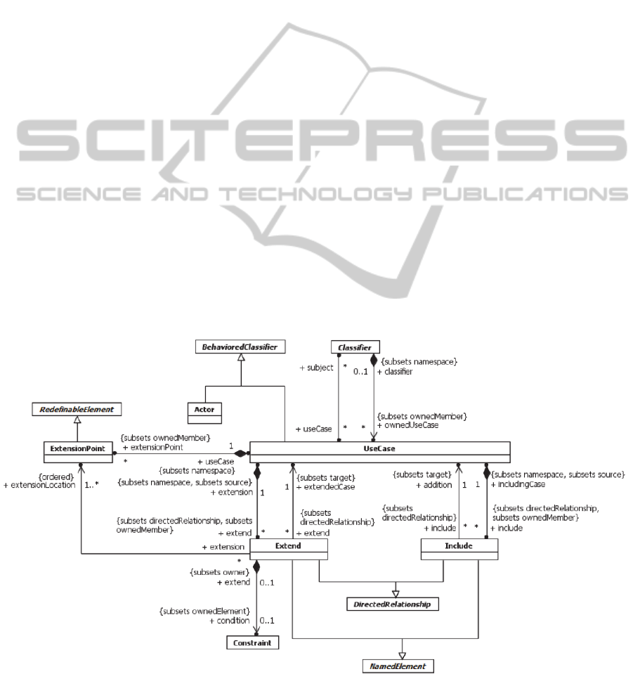
Figure 1: Use Cases portion of the UML metamodel (taken from (OMG, 2013)).
ICSOFT-PT2014-9thInternationalConferenceonSoftwareParadigmTrends
96

2.2 Use Case Relations in the UML
Metamodel
The UML metamodel for use cases (see Figure 1)
supplies two use case relations, namely Extend and
Include, which allow the modeler to organize a use
case behavior into further refined behaviors that are
imported (included) in a bigger, more complex, use
case, and optional or conditional behaviors that may
extend the bigger use case by the actors’ option or
when certain (pre-) conditions hold.
Besides those two relations, as a (Behaviored)
Classifier, a use case may also specialize another use
case through an Inheritance relation. A use case that
inherits from another use case, specializes its
behavior and inherits all its features (included use
cases, associated domain model classifiers and
features, etc.) (OMG, 2013).
3 UI MODELING AND OTHER
RELATED WORK
3.1 Introduction
Interaction between the user and the system takes
place on the UI. The user interface style affects the
nature of this dialogue. Common user interface
styles include (Dix et al, 1998) command line
interfaces, menu-driven interfaces, form-fills and
spreadsheets, point-and-click, WIMP (Windows,
Icons, Menus and Pointers), among others. A given
UI can combine one or more of these interface
styles. What is commonly called a Graphical User
Interface (GUI) is an UI that mixes the WIMP
interface style with any other.
UI is also affected by dialog design and layout.
The way information is presented to the user, and
the screen layout for entering information, have
important effects on the system usability.
User Interface Models (UIM) can be used to
model a user interface of a given system. Dix et al.
(1998) identify the following set of UI model
concerns:
The definition of allowed system UI states and
transitions;
The specification of allowed sequences of user
events and system events on the UI;
The establishment of a link between the events
on the UI and the core system's functionality;
How is the information (abstractly) presented
to the user;
What is the concrete aspect of that
presentation?
The concerns identified above are addressed by
disparate UIM sub-models or model views.
Martikainen (2002) defines a user interface
model as “a declarative specification of a user
interface, including its appearance, the connections
between its elements or how it interacts with the
underlying application functionality”.
A UI model represents all the relevant aspects of
a user interface in some type of interface modeling
language or notation. UI models are generally task-
oriented and use high abstraction levels to achieve
device independence and UI description reuse
(Puerta & Eisenstein, 1999; Martikainen, 2002).
User Interface model-based development
techniques build a more or less declarative User
Interface Model (UIM), which is typically composed
of various sub-models, or model views. This UIM
captures the relevant aspects of the UI and is
typically developed using a model-based user
interface development environment (MB-UIDE).
Different MB-UIDEs use different kinds of models
specified with different kinds of modeling
languages.
Typically, a model-based UI development
process begins with the construction of a task model.
Afterwards, an abstract user interface model
(AUIM) is built and at the end of the process a
concrete user interface model is constructed.
The next subsection analyses task analysis
techniques, focusing its attention on CTT, a task
modeling notation.
3.2 Task Analysis and Modeling
Task analysis is a technique that may be used to
analyze the way people act when performing their
jobs. Task analysis can be approached by the
following ways (Dix et al, 1998):
Task decomposition: Decomposes tasks into
subtasks, minding the order in which these are
performed (e.g.: HTA - Hierarchical Task
Analysis);
Knowledge-based techniques: Focus on what
the users need to know about the objects and
actions involved in a task, and how that
knowledge is organized (e.g.: TAKD - Task
Analysis for Knowledge Description);
Entity-relation-based analysis: Puts an
emphasis on identifying actors and objects, the
relationships between them and the actions
they perform (e.g.: ATOM - Analysis for Task
Object Modeling Method).
RefiningUseCasesthroughTemporalRelations
97
CTT (ConcurTaskTrees) is a widely adopted
graphic notation for specifying task models. It has a
hierarchical structure, just like hierarchical task
analysis, which enables reusable task structures to be
defined at both a low and a high semantic level.
ConcurTaskTrees enables the use of operators
that link subtasks at the same abstraction level,
which describe a temporal relationship between
tasks. This type of information was not usually
formally present in task models. By allowing the
modeler to use these operators it is possible to
express clearly the logical temporal relationships,
which shall be taken into account in the user
interface implementation to allow the user to
perform at any time the tasks that should be active
from a semantic point of view.
The operators used by CTT to describe the
temporal relationships are (Paternó et al, 1997;
Paternó, 2003; W3C, 2014):
T1 ||| T2, interleaving: the actions of tasks T1
and T2 can be performed concurrently,
without specific constraints;
T1 |=| T2, order independence: the actions of
tasks T1 and T2 can be performed in any
order;
T1 || T2, parallelism: the actions of tasks T1
and T2 can be performed in true parallelism;
T1 |[ ]| T2, synchronization: tasks T1 and T2
must synchronize on some actions and may
exchange information;
T1 >> T2, enabling: when task T1 is
terminated, task T2 is activated;
T1 []>> T2, enabling with information
passing: when task T1 is terminated, task T2 is
activated, and T1 passes information to T2;
T1 [> T2, deactivation/disabling: when one
action from task T2 occurs, T1 is deactivated;
T1 [] T2, choice: it is possible to choose one
task from the ones presented;
T1*, iteration: the task is iterative;
T1(n), finite iteration: the number of times the
task is performed is specified;
[T1], optional task: task execution is not
mandatory;
T1 |> T2, suspend-resume: T2 interrupts the
execution of T1. When T2 finishes executing,
T1 may resume its execution.
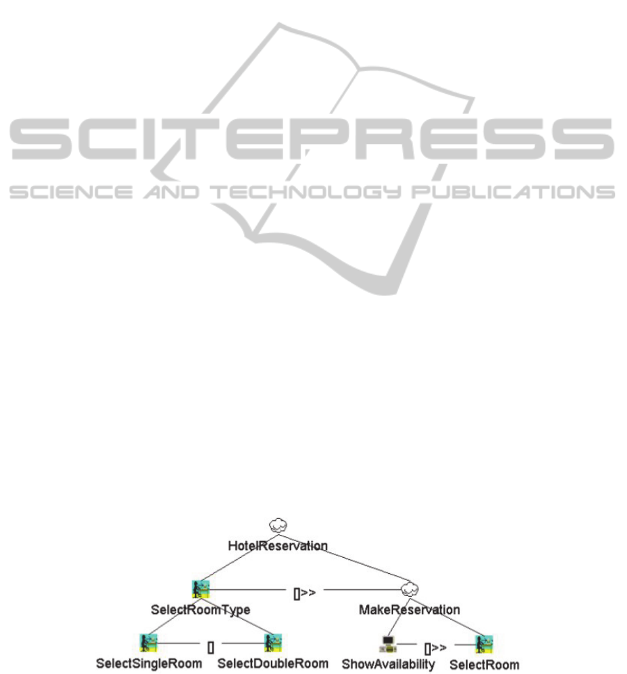
An example of a task model using the CTT
notation is shown in Figure 2. In CTT tasks can be
allocated to the user or the system. There can also be
abstract tasks, which may have subtasks allocated to
different categories, and interaction tasks, which are
in fact user tasks but have an immediate effect on
the system and yield immediate feedback from it.
3.3 Other Related Work
Approaches for systematizing the gap bridging
between user tasks, or usage scenarios, and the
application object model have been proposed.
Martinez et al. (2002) and Elkoutbi et al. (2006)
detail use case scenarios through sequence or
collaboration diagrams and label them with UI
constraints. Constantine et al. (2003)(Constantine,
2006) propose the use of essential use cases and task
flows. Other proposals were made by Kantorowitz
(2003) and Mahfoudhi et al. (2001).
With respect to proposing the use of temporal or
precedence relations in use case modeling, there are
also some references in the literature, such as (Somé,
2007), which introduces two constructs to be used
when describing a use case: Follows, which
identifies the use cases that the one being specified
must follow; and Enable/Enable in Parallel, which
identifies the use cases enabled by the one being
described.
Pow-Sang et al. (2008) propose the use of a
<<precede>> relation between use cases, but the
goal is to denote precedence of construction in use
case-driven development processes.
Figure 2. Example of a CTT task model (taken from (W3C, 2014)).
ICSOFT-PT2014-9thInternationalConferenceonSoftwareParadigmTrends
98

4 EXTENDING THE UML
METAMODEL FOR USE CASES
4.1 Introduction
After discussing temporal relations in the context of
use case models, this section proposes an extension
to the UML metamodel for use cases, in order to
empower it with temporal use case relations, and for
enabling modeling use cases at a very detailed level,
by associating use cases to specific features in their
subject classifiers.
4.2 Discussing Temporal Relations in
the Context of Use Case Models
In the following discussion, we will use the term top
level use case to refer to an independent use case
directly linked to an actor (Cruz & Faria, 2010;
Cruz, 2014). Top level use cases are not included
and do not extend any other use case. Conversely,
they may include and be extended by other use
cases, just as any other use case can.
Task models and use case models have different
goals, namely to model user and system tasks within
an interaction, for the former, and to model the
functions made available by the system to its users,
for the latter. Use case models aim, also, to constrain
the interactions’ context, namely the way the system
and the user interact. Nevertheless, UML does not
address task modeling, being the use case model the
most appropriate way of approximating it. Despite
that, use case models do not comprise temporal
relations as the ones seen in task models.
The top level node (root) of a task model,
however, may roughly correspond to a top level use
case. Subsequently, a task model (tree) decomposes
its root into detailed sub-tasks, specifying how these
are temporally related to perform the root task. Each
sub-task can be further decomposed into more sub-
tasks. A task can be the user’s or the system’s
responsibility.
A top level use case, or any other use case, may
be decomposed into other use cases that may be
included in, or may extend, the first one. Included
and extending use cases decompose the including
use case functionality into sub-functions. UML
offers no way of orchestrating those use cases, either
by having a use case enable or disable another, or by
providing a set of alternative use cases.
While use case inclusions are mandatory
behaviors (sub-functions) that must be instantiated
when performing the corresponding top use case,
extension use cases are commonly understood as
being optional use cases, if they don’t have a
condition, or conditional use cases, when a
triggering condition is set.
In a use case model, all use cases directly
available to an actor, are available in parallel to any
user playing the role of the actor. So the user may
always choose the use case within which he/she
wants to interact with the system. So directly
accessible use cases are inherently concurrent, and
may happen in parallel or in any order (although
through pre- and post-conditions the modeler is able
to constrain order or parallelism/concurrency).
Although, while specifying a use case through an
activity model, it is possible to specify the forking of
parallel activities and the synchronization of
activities, synchronization between use cases is not
possible to model in a use case model.
Use case iteration or finite iteration do not make
sense, as a use case can be performed any number of
times. Despite that, UML allows to define
multiplicity in an Actor-UseCase association,
enabling a one-to-many association between an
Actor and a UseCase, meaning that the actor may
initiate the use case behavior iteratively.
Optional and conditional use cases may already
be modeled with use case Extend relation.
From this discussion, follows that the use case
model expressiveness could extremely benefit from
the following temporal relations:
Use case enabling, with or without
information passing: this would allow
imposing an order on included or extending
use cases;
Use case deactivation, and
Use case choice: this would allow some types
of alternative scenarios being modeled directly
in the use case model.
The following subsection proposes a UML
metamodel extension for enabling the new temporal
use case relations referred to above.
4.3 New Use Case Relations
Figure 3 illustrates the proposed additions to the
UML metamodel for use cases. The defined
metamodel extension adds three new use case
relations.
The Enabling relation may be defined between
two use cases included within another use case that
sets a common context. Only when the enabling use
case is performed, the enabled use case may be
performed by the actor accessing them. This is
equivalent to the following OCL precondition in the
enabled use case, assuming that a
BehavioredClassifier method isperformed() exists,
RefiningUseCasesthroughTemporalRelations
99
yielding whether a use case behavior has already
been performed in the current execution trace:
Context enableduc pre: enablinguc.isperformed()
(1)
The Deactivation relation may be defined
between two use cases included in/extending another
use case that sets a common context. The execution
of the deactivating case disables the deactivated one.
This is equivalent to the following OCL
precondition in the deactivated use case:
Context deactivateduc pre:
not deactivatinguc.isperformed()
(2)
The Choice relation enables the definition of
alternative use cases included in/extending another
use case that sets a common context. By performing
one of the choice related use cases, the actor disables
all the others. This is equivalent to the following
OCL precondition in all the alternative use cases uc
i
(i=1… n):
Context uc
i
pre:
not uc
1
.isperformed() and
not uc
2
.isperformed() and … and
not uc
i-1
.isperformed() and
not uc
i+1
.isperformed() and … and
not uc
n
.isperformed()
(3)
Temporal, task-model-like, relations between
use cases allow to further increase the expressive
power of use case models, namely by incorporating
interaction relevant constraints, that also apply to
use case behaviors, and thus enable using use case
models as a basis for UIM derivation within a
model-driven development setting (Cruz & Faria,
2010).
Just like with Include and Extend relations, the
concrete notation for task model-like relations
makes use of proper stereotyping of use case
relations with “enable”, “deactivate” or “choice”.
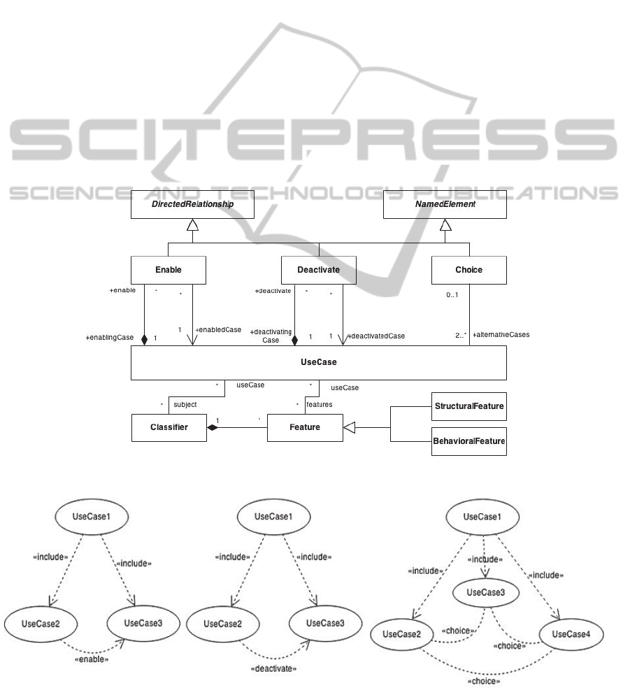
Figure 3: Extending the UML metamodel with three new use case relations.
Figure 4: Proposed concrete notation for the three new temporal relations.
ICSOFT-PT2014-9thInternationalConferenceonSoftwareParadigmTrends
100
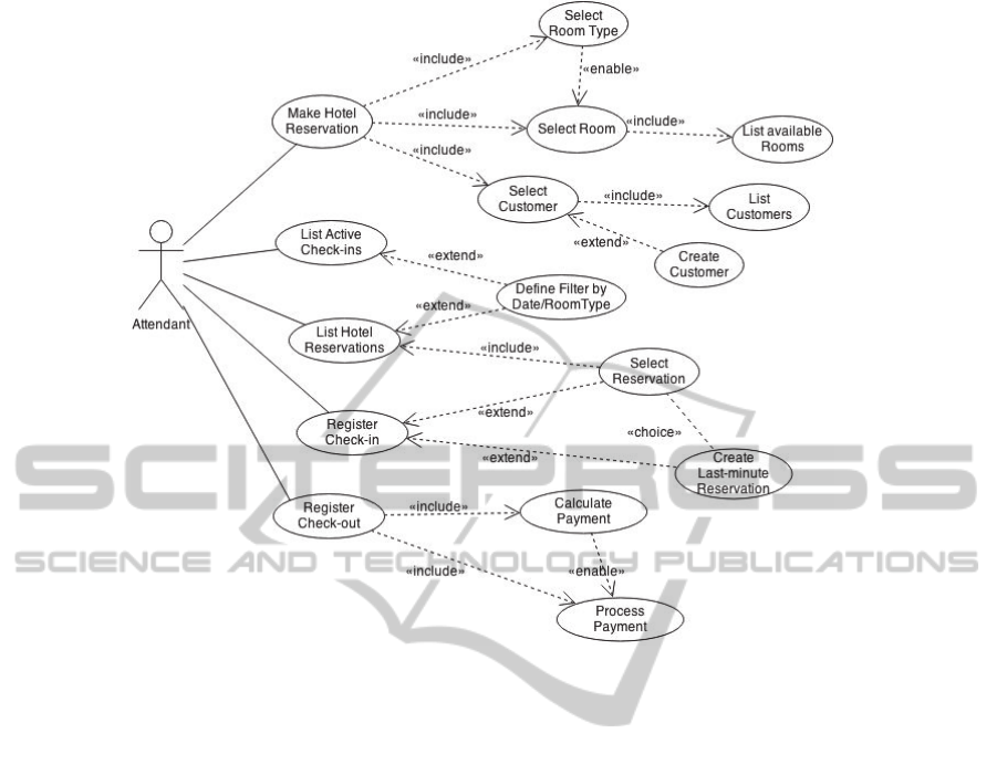
Figure 5: Example use case model (UCM) for a Hotel Management System.
Figure 4 shows the concrete notations for the
new proposed use case relations. When only two use
cases are related through the choice relation, the
concrete notation for choice may also be the one in
Figure 5.
Besides the three new use case temporal
relations, the proposed metamodel also allows the
modeler to define use cases that are at decreasing
abstraction levels, for instance by including a use
case whose subject is not a complete Classifier, but a
structural or behavioral feature of one. For this, the
Use Case Metamodel is extended with an association
to Feature (e.g.: Property, Operation). In Figure 3,
one can see that, besides the Classifier subject, a use
case may have associated features, from its subject
Classifiers, which are affected by its behaviors.
For example, one can define an enable relation
between use cases associated to an entity and to
allowable CRUD operations, but it is also possible to
have an enable relation between use cases associated
to entity features stating, for instance, that some
operation can only be performed after setting the
value of a given entity property or use case
parameter.
In fact, a use case can be inner defined by
including use cases, whether it is associated to a
domain Entity or not. We call the use case that is
defined at the expenses of included cases associated
to entity properties or use case variables an
aggregator use case. At its lowest abstraction level,
this kind of use cases, together with the properly
stereotyped use case relations, allow the modeler to
define which set of attributes must be set first, and
which depend on others, or are deactivated by
setting other attributes. At this modeling level, it is
possible to associate an included use case to a class'
attribute, user-defined operation, or CRUD
operation. It is allowed to have a use case, associated
or not to any class, which has several included use
cases associated to different entity classes or
features.
4.4 Example
Figure 5 shows an example of using use case
relations, with some of the new temporal relations
for relating use cases detailing another use case. A
domain model, integrated to this use case model, is
expected to exist (Frankel, 2003; Cruz&Faria, 2010).
Note that the first use case, “Make Hotel
Reservation”, roughly corresponds to the task model
in Figure 2, but is oriented not to the user tasks in
the system and corresponding system feedback, but
to the system offered functionality, as expected from
a use case model. “Make Hotel Reservation”
includes three use cases. The enable relation ensures
RefiningUseCasesthroughTemporalRelations
101

that the user/actor can only interact with the system
within “Select Room”, after completing the
interaction within “Select Room Type”. “Select
Room” includes “List available Rooms”, from which
list a room must be selected by the user/actor.
“Select Customer” use case may be initiated
before or after selecting a room type and a room.
Selecting a customer includes listing customers, but
the user/actor may extend it with “Create
Customer”.
In “Register Check-in” the user must choose
from selecting a reservation, from the list of existing
hotel reservations, or create a new last-minute
reservation. Thus, only one of the two extensions is
executed in each “Register Check-in” execution.
5 CONCLUSIONS
Based on existing task-models’ temporal relations,
this paper proposes, for using in the use case
modeling framework, three new temporal relations.
For that purpose, an extension to the UML
metamodel for use cases is proposed, together with
concrete notations for the new use case relations.
The proposed relations make possible the
inclusion of more detail in the use case model, and
thus contribute to better UI models, within the
context of an automatic model-to-model
transformation process between a use case model
and a UIM.
Ongoing work, within project Amalia (Agile
Model-driven Application Development Method and
Tools), is developing a modeling tool for the
integrated development of a system domain, use
case and UI models.
REFERENCES
Constantine, L., Windl, H., Noble, J., Lockwood, L., 2003.
From abstraction to realization: Canonical abstract
prototypes for user interface design. Revised Working
Paper: http://www.foruse.com/articles/canonical.pdf.
Constantine, L., 2006. Activity modeling: Toward a
pragmatic integration of activity theory with usage-
centered design. Technical Paper. Revision 2.0.
Cruz, A.M.R., 2014. A Pattern Language for Use Case
Modeling. In Proceedings of the 2nd Int’l Conf. on
Model-Driven Engineering and Software Development
(Modelsward 2014), Lisboa, Portugal, INSTICC Press.
Cruz, A.M.R., Faria, J.P., 2010. A Metamodel-based
Approach For Automatic User Interface Generation. In
13th ACM/IEEE Int’l Conf. on Model Driven Eng.
Languages and Systems (Models 2010), Part 1, LNCS
6394, pp.256-270, Oslo, Norway, Springer.
Dix, A., Finlay, J., Abowd, G., Beale, R., 1998. Human-
Computer Interaction. Prentice Hall, 2nd edition.
Elkoutbi, M., Khriss, I., Keller, R.K., 2006. Automated
prototyping of user interfaces based on UML
scenarios. Journal of Automated Software
Engineering, 13(1):5-40, January.
Frankel, D.S., 2003. Model Driven Architecture - Applying
MDA to Enterprise Computing. Wiley Publishing,
Inc., Indianapolis.
Kantorowitz, E., Lyakas, A., Myasqobsky, A., 2003. A use
case oriented user interface framework. Proceedings
IEEE International Conference on Software - Science,
Technology and Engineering (SwSTE'03), pp 93-100.
Mahfoudhi, A., Abed, M., Tabary, D., 2001. From the
formal specications of users tasks to the automatic
generation of the HCI specications. People and
Computers XV - Interaction without Frontiers. Joint
Proceedings of HCI 2001 and IHM 2001, pp 331-347.
Martikainen, M., 2002. An XML-based framework for
developing usable and reusable user interfaces for
multi-channel applications. Pro gradu thesis, report,
Dept of Computer Science, University of Helsinki.
Martinez, A., Estrada, H., Sánchez, J., Pastor, O., 2002.
From early requirements to user interface prototyping:
A methodological approach. In Int’l Conf. ASE 2002,
pp 257-260.
OMG, 2013. OMG Unified Modeling Language (OMG
UML). Version 2.5, 2013. Available in
http://www.omg.org/spec/UML/2.5/Beta2/.
OMG, 2013a. Action Language for Foundational UML
(Alf) - Concrete Syntax for a UML Action Language,
Version 1.0.1, 2013.
Paternó, F., Mancini, C., Meniconi, S.. ConcurTaskTrees:
A diagrammatic notation for specifying task models.
In INTERACT '97: Proc. of the IFIP TC13 Int’l Conf.
on HCI, pp 362-369, London, UK, Chapman & Hall.
Paternó, F., 2003. The handbook of Task Analysis for
Human-Computer Interaction, chapter
ConcurTaskTrees: An engineered notation for task
models, pp 483-503. D. Diaper and N. Stanton.
Pow-Sang, J.A., Nakasone, A., Imbert, R., Moreno, A.M.,
2008. An Approach to Determine Software
Requirement Construction Sequences based on Use
Cases. In Proc. of Advanced Software Engineering
and its Applications, ASEA 2008, pp. 17-22.
Puerta, A., Eisenstein, J., 1999. Towards a general
computational framework for model-based interface
development systems. In Proc. of the 4th Int’l Conf.
on Intelligent UIs, pp 171-178, NY, USA, ACM Press.
Somé, S. S., 2007. Specifying Use Case Sequencing
Constraints using Description Elements. In Sixth Int’l
Workshop on Scenarios and State Machines
(SCESM’07). IEEE CS.
W3C, 2014. MBUI – Task Models. W3C Working Group
Note 08 April 2014. Available at
http://www.w3.org/TR/task-models/
ICSOFT-PT2014-9thInternationalConferenceonSoftwareParadigmTrends
102
