
Robot Trajectory Optimization for the Relaxed End-effector Path
Sergey Alatartsev, Anton Belov, Mykhaylo Nykolaychuk and Frank Ortmeier
Chair of Software Engineering, Otto-von-Guericke University, Universit¨atsplatz 2, Magdeburg, Germany
Keywords:
Trajectory Optimization, Minimum-jerk Trajectory, Path Relaxing, Pattern Search, Rubber-band Algorithm.
Abstract:
In this paper we consider the trajectory optimization problem for the effective tasks performed by industrial
robots, e.g., welding, cutting or camera inspection. The distinctive feature of such tasks is that a robot has to
follow a certain end-effector path with its motion law. For example, welding a line with a certain velocity has
an even influence on the surface. The end-effector path and its motion law depend on the industrial process
requirements. They are calculated without considering robot kinematics, hence, are often “awkward” for the
robot execution, e.g., cause high jerks in the robot’s joints. In this paper we present the trajectory optimization
problem where the end-effector path is allowed to have a certain deviation. Such path is referred to as relaxed
path. The goal of the paper is to make use of this freedom and construct the minimal-cost robot trajectory. To
demonstrate the potential of the problem, jerk of the robot joint trajectory was minimized.
1 INTRODUCTION
All robot movements can be divided into two cate-
gories: effective and supporting movements (Alatart-
sev et al., 2013). Effective movements are required
to perform a certain task, e.g., welding, deburring
or glue dispensing. Supporting movements are re-
quired to move from one effective task to another,
e.g., motion between two welding seams. Effective
movements are task-depended, therefore, robot end-
effector path and its motion law are often defined in
a strict way to meet the requirements of the industrial
process. As a consequence, the obtained robot trajec-
tory is “awkward” for the robot execution,e.g., causes
high jerks in robot joints.
Effective tasks often allow a freedom of execu-
tion. For example, laser-welding can be performed
with a set of possible tool orientations (Kov´acs, 2013)
or cutting can be performed with a set of possible tool
positions and orientations (Alatartsev and Ortmeier,
2014). As a consequence, the end-effector path is not
unique. There is a continuous set of admissible paths,
that are equal in terms of quality of task performing.
However, such paths are not equal in terms of robot
kinematics and lead to different robot trajectories. We
call the set of admissible paths a relaxed path.
We present the general problem of finding such
an end-effector path from the relaxed path that would
lead to a minimum cost robot trajectory. It is assumed
that motion law is given, e.g., imposed by an indus-
trial application or already optimized. The heuristic
approach proposed in this paper is independent from
a way of path relaxation and a cost function. In this
paper we are interested in the continuous planning
rather than in point-to-point trajectories, e.g., motion
law should be maintained throughout the whole path
and not only in its via-points. The trajectory cost is a
domain-dependent parameter and can be, for exam-
ple, time, energy or material influence metric. We
show on a robot application from the medical-domain
that by exploiting the freedom of path relaxation the
trajectory cost can be significantly reduced.
2 BACKGROUND
Robot trajectory is specified with a geometrical path
and a motion law by which the path must be tracked
(Biagiotti and Melchiorri, 2008). The path can be
specified either in the task space (T-Space) as a se-
quence of robot end-effector positions and orienta-
tions (Path
EF
) or in the configuration space (C-space)
as a sequence of robot joints angles (Path
R
), see Fig.
1. By the end-effector path, we imply the path for the
tool center point (TCP) or end of arm (EOA) point. To
obtain the robot trajectory, the motion law has to be
applied either to the end-effector path or to the robot
joint path and then it is denoted as ML
EF
and ML
R
re-
spectively. Converting between T-space and C-space
is done by means of Inverse Kinematics (IK) and For-
385
Alatartsev S., Belov A., Nykolaychuk M. and Ortmeier F..
Robot Trajectory Optimization for the Relaxed End-effector Path.
DOI: 10.5220/0005093103850390
In Proceedings of the 11th International Conference on Informatics in Control, Automation and Robotics (ICINCO-2014), pages 385-390
ISBN: 978-989-758-039-0
Copyright
c
2014 SCITEPRESS (Science and Technology Publications, Lda.)
T-space
C-space
Path
EF
+
=
Path
R
+
=
Forward
Kinematics
Inverse
Kinematics
ML
EF
Path
EF
(ML
EF
(t))
ML
R
Path
R
(ML
R
(t))
Trajectory
Trajectory
Figure 1: Overview of the robot trajectory calculation.
ward Kinematics (FK) transformations (Craig, 2005).
FK obtains a unique end-effector pose for the given
robot configuration. IK obtains a set of possible robot
configurations for the given end-effector pose.
The decision on what path and motion law are re-
quired to obtain the robot trajectory is based on the
type of movement the robot has to make. For support-
ing movements, the motion law ML
R
is specified for
the C-space path Path
R
, as it is not important how ex-
actly the robot end-effector should move. On the con-
trary, effective movements are task-depended, there-
fore, robot end-effector path Path
EF
and its motion
law ML
EF
are often defined in the T-space to meet
the requirements of the industrial process. In this pa-
per trajectory optimization problem is observed for
the effective tasks. Therefore, formal definitions for
the Path
EF
and ML
EF
are given below.
End-effector path is defined as follows:
Path
EF
= (P
1
,..., P
n
), where n is a number of
via-points. The via-points belong to 6D T-space,
P
i
∈ R
6
, where three dimensions stand for position
and the remaining three dimensions stand for orien-
tation (when using the Euler angle convention). The
path is normally represented by a smooth interpola-
tion function in the domain [0,1]. Motion law is a
function that maps the time value from [0,T] to the
value from [0,1], i.e., ML
EF
: [0, T] → [0,1], where T
is the desired motion duration.
The output of the trajectory planning is the
C-space robot trajectory as it uniquely describes
the robot motion. It is a tuple of trajectories for
every robot joint. C-space trajectory is obtained by
applying the motion law ML
R
to the path Path
R
, i.e.,
IK(Path
EF
(ML
EF
(t))) = Path
R
(ML
R
(t)) = Tra j
R
(t).
3 PROBLEM DESCRIPTION
3.1 Path Relaxation
It is important to emphasize that relaxing the path is a
domain-dependent process. However, general meth-
ods can be inherited from the path planning domain,
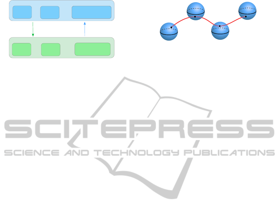
V
1
V
2
V
3
P
2
P
1
P
3
P
4
V
4
Figure 2: Relaxed path RelPath
EF
= (V
1
,...,V
4
) that con-
sists of spheres and path Path
EF
= (P
1
,..., P
4
) that belongs
to it. Smooth function of the end-effector movement is de-
picted with red curve.
e.g., to apply intervals to each coordinate instead of
a single value (Berenson et al., 2011). Path freedom
was also applied in the task sequencing domain, when
for the laser welding application, the truncated cones
are used instead of the T-space points (Kov´acs, 2013).
We define relaxed end-effector path as follows:
RelPath
EF
= (V
1
,...,V
n
), where n is a number of via-
volumes. Via-volume is a subset of the 6D T-space,
i.e., V
i
⊂ R
6
.
The path Path
EF
belongs to the relaxed path
RelPath
EF
, when all its points belong to the corre-
sponding volumes, i.e., P
i
∈ V
i
, where i ∈ 1,...,n, see
Fig. 2. It should be clear that an infinite number of
possible Path
EF
belongs to the RelPath
EF
. This fact
is used to search for such a Path
EF
that leads to a
minimal-cost robot trajectory.
3.2 Problem Statement
The problem is formulated as follows:
Given a relaxed robot end-effector path
RelPath
EF
, end-effector motion law ML
EF
and a trajectory duration T, find such
a path Path
EF
belonging to RelPath
EF
that leads to a minimal-cost robot C-space
trajectory Traj
R
(t) = IK(Path
EF
(ML
EF
(t))),
where t ∈ [0,T].
Note that the problem does not require constraints or
cost function to be convex. The optimization cost
could be: energy, jerk or any domain-specific param-
eter. During optimization, it is important to verify that
a C-space trajectory is feasible, i.e., maximum joints
velocities, accelerations bounds and joint limits are
not violated.
3.3 Problem Discussion
Modeling the Problem: The problem stated in this
paper bears a resemblance to the well-known geo-
metrical problem - Touring a sequence of Polygons
Problem (TPP) (Dror et al., 2003). The goal of the
TPP is to construct a minimal-cost tour through the
ICINCO2014-11thInternationalConferenceonInformaticsinControl,AutomationandRobotics
386

sequence of polygons. Solution of the TPP is a list
of points through which the tour visits each poly-
gon. This problem can be rephrased to fit the prob-
lem stated in this paper. Find a minimal-cost C-space
trajectory such that its T-space path visits every given
multi-dimensional volume. This way techniques for
TPP can be applied for trajectory optimization. In
this paper we applied Rubber-band Algorithm (RBA)
(Pan et al., 2010) that is used for solving TPP.
State of the Art in Trajectory Optimization: Tra-
jectory optimization problem received large attention
for the last 30 years and numerous variations of this
problem exist. The comprehensive overview on state
of the art in robot trajectory optimization can be found
in the survey (Ata, 2007). In general, smooth func-
tions are used for the T-space path interpolation and
it is often assumed that via-points should be visited
strictly without any deviation (Liu et al., 2013). The
problem proposed in this paper is different from the
trajectory tracking problem (Ata and Myo, 2005), as
we are concerned in making the end-effector trajec-
tory more suitable for a robot, rather than in a precise
following of the given end-effector trajectory. There
are approaches mainly oriented on supporting tasks as
constraints are set in the C-space, e.g., (Chettibi et al.,
2004) or (Gasparetto and Zanotto, 2010). Continuous
end-effector path planning problem for the effective
tasks instead of a point-to-point movements was ob-
served by (Olabi et al., 2010). A robot has to strictly
follow the end-effector path and its motion-law was
optimized. In this paper, we do exactly the opposite –
the path geometry is optimized, however, the motion-
law is followed strictly.
Path Relaxation in Trajectory Optimization: In
(Aspragathos, 1998) path is relaxed by extending the
given end-effector path with possible deviation. The
generation of the C-space trajectory is computation-
ally expensive for a large number of end-effector path
via-points. Therefore, Aspragathos proposed an algo-
rithm to minimize the number of via-points and as a
consequence to reduce the number of IK calls but still
guarantee that the end-effector is within a certain de-
viation from the given end-effector path. In contrast,
our problem has a fixed number of via-points but it
allows them to vary within the allowed freedom.
Another similar problem was proposed by (Kolter
and Ng, 2009) who used cubic splines to construct
T-space smooth trajectories. All constraints are con-
vex and are set for the T-space path via-points. Then
the problem is solved with a general purpose convex
solver. The presented approach is powerful and can
incorporate numerous objective functions from the T-
space, except minimization of the trajectory duration
time. Cost functions from the C-space can also be
used but in that case Jacobian approximation should
be performed along the trajectory. As a consequence,
only one of many IK solutions is considered. The
main limitation is that this technique is not suitable
for the cases when the path must go through the non-
convex narrow corridors in the robot C-space. That is
often the case in industrial robotics during handling
the effective tasks.
The freedom for the paint gun orientation was de-
scribed by (From et al., 2011). They proposed an
approach for the real-time calculation of the optimal
paint gun orientation for each time step for the given
constant velocity value. The minimal-cost here means
that the displacements of the paint gun are minimized.
The freedom is given as convex constraints for orien-
tation. The objective function must be convex as well.
The problem presented in this paper is a generaliza-
tion of their problem, as the freedom is provided both
for the end-effector orientation and position. We do
not require the constraints or objective function to be
convex. There is also no requirement that velocity has
to be a constant value, it can be an arbitrary function.
Summarizing, the previously described ap-
proaches often ignore freedom of the path. Those ap-
proaches that exploit path freedom are either domain-
specific or not applicable for the industrial applica-
tions. The idea proposed in this paper does not com-
pete with the related approaches but rather attempts to
enhance their scope. The proposed problem definition
is domain-independent and formulated with no de-
pendence on the solving approach, as a consequence,
there are no special requirements for the constraints
or the cost function.
4 CASE STUDY
We illustrate the usefulness of the proposed idea with
the medical application, 3D-angiographythat is based
on the C-Arm and provides computed tomography3D
volumes. Such 3D volume is obtained by stitching
multiple picture-scans taken from different positions.
The C-arm is a horseshoe-shaped device mounted on
the robot and it consists of two components: the X-
ray source and the detector, see Fig. 3 and Fig. 4. We
consider only degrees of freedom of the robot. For
simplicity, degrees of freedom in the C-arm device
are ignored.
It is critical to know the exact position and a
time when each picture was taken. Imprecise trajec-
tory following influences the final 3D volume quality,
i.e., makes it blurry. The path of the X-ray source
RobotTrajectoryOptimizationfortheRelaxedEnd-effectorPath
387
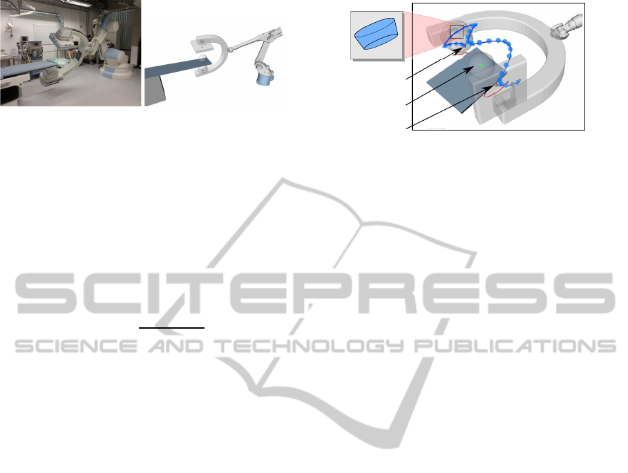
Figure 3: Layout of the robot equipped with C-arm.
is specified for a certain task without considering
robot kinematics. One possible way to obtain high-
quality source trajectory is to make the robot trajec-
tory smooth by minimizing joint jerks. Jerk mini-
mization reduces the error of the path tracker. In ad-
dition, trajectories with small jerk reduce wear of the
robot and, as a consequence, increase its life span (Si-
mon, 1993). Thus, the objective to minimize is the
maximum joints jerks throughout trajectory duration:
max
i∈[1,...,ndo f]
( max
t∈[0,...,T ]
(
∂
3
Tra j
R
i
(t)
∂t
3
)) → min (1)
where ndof is the number of robot degrees of free-
dom.
This application scenario allows a certain freedom
for the path. For example, the source might have the
deviation of being closer or further to the point of in-
terest (in our scenario this deviation is 0.02 m.). In
addition, the approaching vector might have deviation
of 6
◦
. This freedom results in the truncated-cone via-
volumes, which the C-arm source path has to visit.
The path and the freedom are shown in the Fig. 4.
In any point of the via-volume, approaching vector of
the source is directed to the point of interest – isocen-
ter. Similar freedom description was used for a laser-
welding application (Kov´acs, 2013).
4.1 Solution Approach
Exhaustive search strategies are impractical due to the
large search space of the presented problem. The con-
vex solvers cannot be applied, as we do not restrict the
problem constraints and cost function to be convex.
The way to solve the problem is to apply a heuris-
tic approach. Heuristics do not guarantee finding the
optimum, however, they can provide near-optimal so-
lution to the real-life scenarios in a reasonable time.
We propose heuristic search that is based on the RBA
(Pan et al., 2010) and on the Pattern Search (PS)
(Hooke and Jeeves, 1961).
The general steps of the optimization process are
presented in Algorithm 1. The algorithm takes re-
laxed robot end-effector path RelPath
EF
, end-effector
motion law ML
EF
and a motion duration T. Its output
X-ray source
Detector
Isocenter
Via-volume
Figure 4: The path of the C-arm X-ray source is designated
with blue, the path of the detector is red. The point of inter-
est is the middle of the sphere. The relaxed path consist of
light-blue volumes.
is an optimized C-space trajectory. Note, that T is a
domain-specific value and if it is too small, then al-
gorithm will not find the solution, as the robot joint
velocity limits will be violated. Initially, the algo-
rithm constructs a feasible path Path
EF
that belongs
to the given relaxed path in Algorithm 1 line 1. In this
application, initial path Path
EF
consists of the central
points of the via-volumes. Then a C-space robot tra-
jectory is calculated with the algorithm GetTraj that
is discussed further and its cost is obtained with the
function GetCost calculated with Formula (1).
The general idea of RBA is to iterate while stop-
ping condition is not satisfied (lines 4 – 17 in Al-
gorithm 1) and in each iteration run through the all
points from the Path
EF
and optimize position and ori-
entation of each point one by one (lines 5 – 16 in Al-
gorithm 1). The stopping condition can be a number
of iterations, an elapsed calculation time, etc.
Optimization of a single point can be done in a
number of ways. In the current implementation PS is
applied (lines 6 – 15 in Algorithm 1). At first, PS
modifies the point P
i
(line 7). The modification is
done as a change of one of the point’s coordinates by
a certain small value. PS loop breaks when no mod-
ification is possible (line 6), i.e., all coordinates have
already been modified. For every new modification,
a new path Path
′
EF
is obtained and a trajectory is re-
calculated with the further described method GetTraj
(line 8) and its cost is obtained (line 9). If the modi-
fication leads to the cost decrease (line 10), then save
the Path
′
EF
, cost
′
, Traj
′
R
(lines 11 –13). The algo-
rithm guarantees that the path worse than the initial
one will not be returned. The algorithm only varies
the path of the end-effector but keeps the motion law
unchanged.
The C-space trajectory Tra j
R
is calculated with
the method GetTraj. The straightforward way to
obtain a C-space trajectory is to map every point of
the end-effector trajectory to the robot configuration
with IK. However, it requires a large number of IK
calls that are normally computationally expensive. In
ICINCO2014-11thInternationalConferenceonInformaticsinControl,AutomationandRobotics
388
Algorithm 1: Heuristic search.
Input: RelPath
EF
, ML
EF
, T
Output: Traj
R
1 Get feasible initial path Path
EF
∈ RelPath
EF
;
2 Tra j
R
← GetTraj(Path
EF
,ML
EF
,T);
3 cost ← GetCost(Traj
R
) ;
4 while stopping condition is not satisfied do
5 foreach P
i
∈ Path
EF
do
6 while Modifications are possible do
7 Path
′
EF
← Modi f y(Path
EF
,P
i
);
8 Traj
′
R
← GetTraj(Path
′
EF
,ML
EF
,T);
9 cost
′
← GetCost(Traj
′
R
) ;
10 if cost
′
< cost then
11 Path
EF
← Path
′
EF
;
12 cost ← cost
′
;
13 Traj
R
← Traj
′
R
;
14 end
15 end
16 end
17 end
18 return Traj
R
;
this paper, at first, Path
R
is obtained by applying IK
only to the Path
EF
via-points. Then Path
R
is inter-
polated with a smooth function with evenly spread
parameter from [0,1]. Later the interpolation param-
eter is rescaled in a way that the end-effector tra-
jectory follows the given ML
EF
. It is done by iter-
ating through the spline domain with a step size of
1\ ( frequency× T). Then, save the obtained spline
values into the array Value
new
and save distances be-
tween end-effector positions for two sequential steps
into the array Parameter
new
. The sum of all values
from Parameter
new
equals to the T-space path length.
Then parametrize these distances to the interval [0,1].
Finally, construct a new spline on the domain param-
eters Parameter
new
and codomain values Value
new
.
This reduces the number of IK calls. In case if more
control on precision is desired, the number of via-
points can be increased.
In this paper cubic splines were applied for inter-
polation of the path and motion law, as they are twice
continuous differentiable and provide constant jerk.
Higher order splines generally suffer from unwanted
high osculation and might lead to a retrograde motion
(Macfarlane and Croft, 2003).
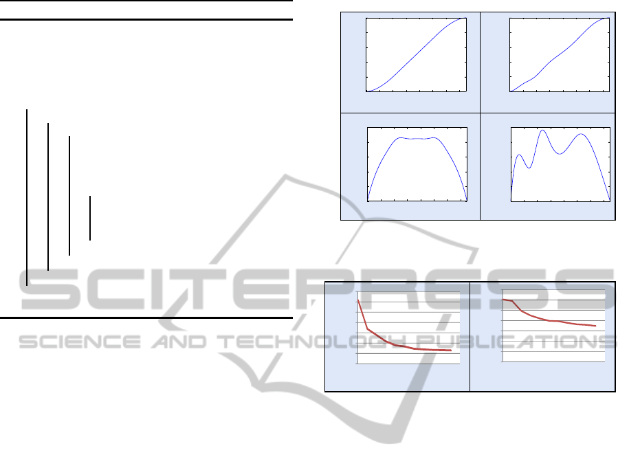
4.2 Evaluation
Two cases are considered: the motion law that re-
sults in a trapezoidal velocity profile (case “A”) and
minimum-jerk optimized velocity profile for the ini-
tial path (case “B”), see Fig. 5. In the case “A”, the
desired trapezoidal velocity allows to obtain picture
points with the constant velocity in the center of the
0.00
0.05
0.10
0.15
0.20
0.25
Velocity (m/s)
0.0
0.2
0.4
0.6
0.8
1.0
Time (s)
Path paramer
0 2
4
6 8 10 12
14
0 2
4
6 8 10 12
14
Path paramer
0 2
4
6 8 10 12
14
Velocity (m/s)
0.00
0.05
0.10
0.15
0.20
0.25
0 2 4 6 8 10 12
14
0.0
0.2
0.4
0.6
0.8
1.0
Case "A"
Case "B"
Motion law
Velocity
Time (s)
Time (s)
Time (s)
Figure 5: Given motion laws and computed end-effector ve-
locities.
20
40
60
80
100
120
140
0
1 2 3 4 5 6 7 8 9 10
Number of iterations
0
5
10
15
20
25
30
35
1 2 3 4 5 6 7 8 9 10
Maximal jerk (Rad/s
3
)
Number of iterations
Case "A"
Case "B"
Maximal jerk (Rad/s
3
)
Figure 6: Convergence rates of optimization for the given
motion laws.
path but that leads to an “awkward” robot C-space tra-
jectory with high jerks, i.e., the cost of the initial tra-
jectory is 123 Rad/s
3
. In the case “B”, the motion law
was optimized to obtain the minimum-jerk C-space
trajectory for the initial path. For motion law opti-
mization, an idea similar to the algorithm proposed
by (Chettibi et al., 2004) was applied. Uniformly dis-
tributed nodes were taken on the motion law curve
and then positions were optimized with the Pattern
Search. The obtained velocity profile in depicted in
Fig. 5. The trajectory cost after motion law minimiza-
tion for the case “B” is 30.2 Rad/s
3
. Due to multiple
calls of inverse kinematics the computational time is
63 min. As the C-arm robot movements are typical
and predefined, it is possible to calculate them offline.
After applying the proposed heuristic for 10 iter-
ations, the cost was decreased to 26 Rad/s
3
for the
case “A” and to the 17.5 Rad/s
3
for the case “B”. The
rate of convergence is depicted in Fig. 6. This study
shows that the end-effector path relaxation leads to
the decrease of the robot trajectory cost regardless of
whether the motion law was optimized or not. How-
ever, it is more effective to relax the path in conjunc-
tion with the motion law optimization.
RobotTrajectoryOptimizationfortheRelaxedEnd-effectorPath
389

5 CONCLUSION
The problem of the minimal-cost trajectory planning
for a given end-effector motion law and a relaxed
path is proposed in this paper. We define this prob-
lem as domain-independent and formulate it with no
regard to the solution method. As a consequence,
we do not impose any requirement on the constraints
or the cost function. It was shown that relaxing the
path can lead to a significant trajectory cost reduc-
tion. This improvement is achieved with no depen-
dency on whether the motion law was defined by an
industrial process or was optimized. The limitation of
the approach follows from its generality. It cannot be
applied in real time, as the used heuristic is computa-
tionally slower than the convex optimization solvers.
One way to achieve better results is to generalize
the problem further by relaxing the motion law, as in
the current problem formulation it is considered to be
given and fixed. Currently, we considered only one
IK solution, e.g., “elbow-up”. However, making use
of the multiplicity of IK solutions might provide bet-
ter results. Robot base location in the environment
greatly influences the cost of the C-space trajectory
obtained for the end-effector path. In many applica-
tions robot base location is not important, or at least
can vary within a certain area. In this paper a greedy
local search method was presented. However, the po-
tential of the problem can be utilized evenmore by ap-
plying more sophisticated search techniques that have
mechanisms to avoid local optimum, e.g., Genetic Al-
gorithm or Variable Neighborhood Search.
ACKNOWLEDGEMENTS
The work in this paper is partly funded by the German
Ministry of Education and Research (BMBF) within
the Forschungscampus STIMULATE (grant number
03FO16101A).
REFERENCES
Alatartsev, S., Mersheeva, V., Augustine, M., and Ortmeier,
F. (2013). On optimizing a sequence of robotic tasks.
In IEEE/RSJ International Conference on Intelligent
Robots and Systems (IROS).
Alatartsev, S. and Ortmeier, F. (2014). Improving the Se-
quence of Robotic Tasks with Freedom of Execution.
In IEEE/RSJ International Conference on Intelligent
Robots and Systems (IROS).
Aspragathos, N. (1998). Cartesian trajectory generation un-
der bounded position deviation. Mechanism and ma-
chine theory, 33(6):697–709.
Ata, A. A. (2007). Optimal trajectory planning of manipu-
lators: A review. Journal of Engineering Science and
Technology, 1:32.
Ata, A. A. and Myo, T. R. (2005). Optimal point-to-point
trajectory tracking of redundant manipulators using
generalized pattern search. International Journal of
Advanced Robotic Systems, 2(3).
Berenson, D., Srinivasa, S., and Kuffner, J. (2011). Task
space regions: A framework for pose-constrained ma-
nipulation planning. International Journal of Robotics
Research (IJRR), 30(12):1435–1460.
Biagiotti, L. and Melchiorri, C. (2008). Trajectory Planning
for Automatic Machines and Robots. Springer Berlin
Heidelberg.
Chettibi, T., Lehtihet, H., Haddad, M., and Hanchi, S.
(2004). Minimum cost trajectory planning for indus-
trial robots. European Journal of Mechanics-A/Solids,
23(4):703–715.
Craig, J. (2005). Introduction to Robotics: Mechanics and
Control. Pearson.
Dror, M., Efrat, A., Lubiw, A., and Mitchell, J. S. B. (2003).
Touring a sequence of polygons. In 35th annual ACM
symposium on Theory of Computing, pages 473–482.
ACM Press.
From, P. J., Gunnar, J., and Gravdahl, J. T. (2011). Optimal
paint gun orientation in spray paint applications – ex-
perimental results. IEEE Transactions on Automation
Science and Engineering, 8(2):438–442.
Gasparetto, A. and Zanotto, V. (2010). Optimal trajectory
planning for industrial robots. Advances in Engineer-
ing Software, 41:548–556.
Hooke, R. and Jeeves, T. A. (1961). Direct search solution
of numerical and statistical problems. Journal of the
ACM, 8(2):212–229.
Kolter, J. Z. and Ng, A. Y. (2009). Task-space trajectories
via cubic spline optimization. In IEEE International
Conference on Robotics and Automation (ICRA).
Kov´acs, A. (2013). Task sequencing for remote laserweld-
ing in the automotive industry. In 23rd International
Conference on Automated Planning and Scheduling
(ICAPS).
Liu, H., Lai, X., and Wu, W. (2013). Time-optimal and jerk-
continuous trajectory planning for robot manipulators
with kinematic constraints. Robotics and Computer-
Integrated Manufacturing, 29(2):309–317.
Macfarlane, S. and Croft, E. A. (2003). Jerk-bounded ma-
nipulator trajectory planning: design for real-time ap-
plications. IEEE Transactions on Robotics and Au-
tomation, 19(1):42–52.
Olabi, A., B´ear´ee, R., Gibaru, O., and Damak, M. (2010).
Feedrate planning for machining with industrial six-
axis robots. Control Engineering Practice, 18(5):471–
482.
Pan, X., Li, F., and Klette, R. (2010). Approximate short-
est path algorithms for sequences of pairwise disjoint
simple polygons. In Canadian Conference on Com-
putational Geometry, pages 175–178.
Simon, D. (1993). The application of neural networks to
optimal robot trajectory planning. Robotics and Au-
tonomous Systems, 11:23–34.
ICINCO2014-11thInternationalConferenceonInformaticsinControl,AutomationandRobotics
390
