
Numerical Investigation of Liquid Flow in Two-, Three- and
Four-Stage Centrifugal Pumps
Nicolas La Roche-Carrier, Guyh Dituba Ngoma and Walid Ghie
University of Quebec in Abitibi-Témiscamingue, School of Engineering’s Department, 445, Boulevard de l’Université,
Rouyn-Noranda, Quebec, J9X 5E4, Canada
Keywords: Centrifugal Pump, Multistage, Impeller, Diffuser, Computational Fluid Dynamics (CFD), Modeling and
Simulation.
Abstract: In this study, a liquid flow in two-, three- and four-stage centrifugal pumps was numerical investigated. The
continuity and Navier-Stokes equations with the k- turbulence model and standard wall functions were
used by means of the ANSYS-CFX code. To enhance the design of the multistage pump, the impacts of the
number of impeller blades, diffuser return vanes and the number of stages on the performances of a
multistage centrifugal pump were analyzed. The results obtained demonstrate that the selected parameters
affect the pump head, brake horsepower and efficiency in a strong yet different manner. To validate the
model developed, the results of the numerical simulations were compared with the experimental results
from the pump manufacturer.
1 INTRODUCTION
Multistage centrifugal pumps are widely used in
industrial and mining enterprises (Peng W., 2008).
For a more performing multistage pump, its design
parameters, such as the number of stages, impeller
blades, diffuser vanes and diffuser return vanes,
angle of the impeller blade, height of the impeller
blade and diffuser vane, the width of the impeller
blade and diffuser vane, the impeller and diffuser
diameter, the rotating speed of the impeller and the
casing geometry must be determined accurately.
Many experimental and numerical studies have been
conducted on the liquid flow through a multistage
centrifugal pump (Huang S. et al., 2006; Miyano M.
et al., 2006; Kawashima D. et al., 2008; Gantar M. et
al., 2002), where Huang S. et al., 2006 had
numerically simulated using a CFD code a three-
dimensional turbulent flow through an entire stage
of a multistage centrifugal pump, including flows in
a rotating impeller and stationary diffuser. They had
found that the reverse flows existed near the
impeller outlet, resulting in the flow field being
asymmetric and unstable. There was considerable
interference on the velocity field at the impeller exit
because of the interaction between the impeller
blades and diffuser vanes. Additionally, Miyano M.
et al., 2006 had experimentally investigated the
impacts of the return vane profile on the
performances of the multistage centrifugal pump to
optimize the stationary components in the multistage
centrifugal pump. It was found, among other things,
that the return vane, whose trailing edge was set at
the outer wall radius of the downstream annular
channel and discharged the swirl-less flow, had a
positive impact on pump performances, while
Kawashima D. et al., 2008 had experimentally
investigated the impacts of the diffuser vane on the
performances of the multistage centrifugal pump,
accounting for the interactions among the diffuser
vane, return vane and next stage impeller. In
addition, Jirout T., 2014 had investigated the liquid
flow in an agitated batch with pitched blade multi-
stage impellers. Effects of various geometrical
parameters of pitched blade multi-stage impellers on
pumping ability have been analyzed. It was shown
the impact of the distance between impellers in
multi-stage configurations, on their pumping
capacity and flow in the mixing bath in comparison
with an independently operating pitched blade
impeller with the same geometry. Furthermore, La
Roche-Carrier et al., 2013 had numerically
simulated the liquid flow in a first stage of a
multistage centrifugal pump consisting of an
impeller, diffuser with return vanes, and casing.
92
La Roche-Carrier N., Dituba Ngoma G. and Ghie W..
Numerical Investigation of Liquid Flow in Two-, Three- and Four-Stage Centrifugal Pumps.
DOI: 10.5220/0005096800920099
In Proceedings of the 4th International Conference on Simulation and Modeling Methodologies, Technologies and Applications (SIMULTECH-2014),
pages 92-99
ISBN: 978-989-758-038-3
Copyright
c
2014 SCITEPRESS (Science and Technology Publications, Lda.)
Effects of the impeller blade height and diffuser
vane height, number of impeller blades, diffuser
vanes and diffuser return vanes, and wall roughness
height on the performances of the first stage of a
multistage centrifugal pump were analyzed. Results
of numerical simulations were compared with the
experimental results from the pump manufacturer.
Thorough analysis of previous works clearly
demonstrated that the research results obtained are
specific to the design parameters and configuration
of the rotating and stationary components in single
centrifugal pumps and multistage centrifugal pumps,
and thus cannot always be generalized. Therefore, in
this study, to enhance the design and performances
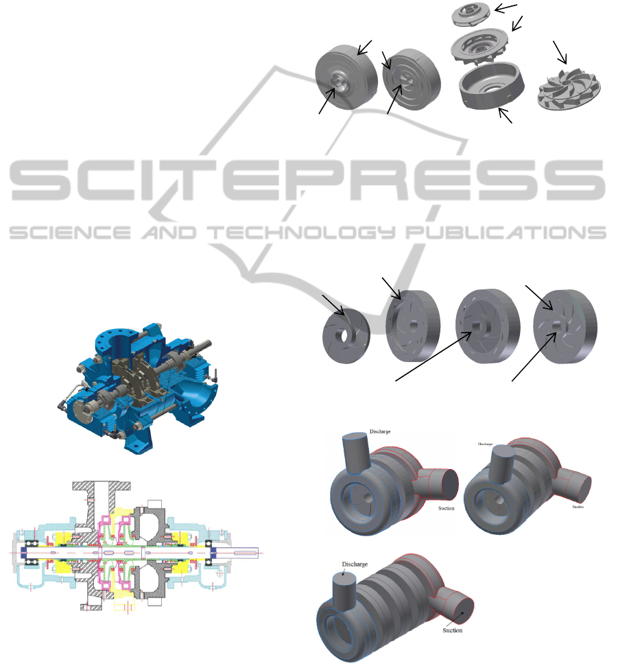
of multistage centrifugal pumps as shown in Fig. 1
for example (Technosub inc.), accounting for the
particularities of the geometry and configuration of
the impeller and diffuser with return vanes, a
numerical investigation was conducted using the
ANSYS-CFX code (Ansys inc., 2011). This was
done to gain further insight into the characteristics of
the three-dimensional turbulent liquid flow through
a multistage centrifugal pump while also considering
various flow conditions and pump design parameters
including the numbers of impeller blades (5, 6 and
7), the number of diffuser return vanes (3, 8, and
11), and the pump stage number (2, 3 and 4).
a) 2-stage centrifugal pump
b) Cross-sectional view of 2-stage pump
Figure 1: Multistage centrifugal pump.
2 GOVERNING EQUATIONS
Fig. 2 shows the model of the first stage of a
multistage centrifugal pump considered in this study.
It consists of an impeller, diffuser with return vanes
and casting.
a) Pump stage b) Stage components
Figure 2: Model of centrifugal pump stage.
To run the numerical simulations, the used domain
fluids of the impeller, diffuser with return vanes and
the multistage centrifugal pumps (2-, 3-, and 4-
stage) are shown in Fig 3.
Suction side (inlet) Discharge side (outlet)
a) Impeller, diffuser and pump stage
b) 2-stage c) 3-stage
d) 4-stage
Figure 3: Domain fluids.
In the centrifugal pump stage’s governing equations
Inlet
Back stage side
Outlet
Return vanes
Blades
Vanes
Impeller
Diffuser with
Return vanes
Casing
NumericalInvestigationofLiquidFlowinTwo-,Three-andFour-StageCentrifugalPumps
93

for liquid flow, the following assumptions were
made: (i) a steady state, three-dimensional and
turbulence flow using the k- model was assumed;
(ii) it was an incompressible liquid; (iii) it was a
Newtonian liquid; and (iv) the liquid’s
thermophysical properties were constant with the
temperature.
To account for these assumptions, the theoretical
analysis of the liquid flow in the impeller passages,
diffuser vane passages and diffuser return vane
passages was based on the continuity and
Navier-Stokes equations (Ansys inc., 2011). For the
three-dimensional liquid flow through these
components of a centrifugal pump stage as shown in
Fig. 2, the continuity equations are expressed by:
0V.
vel
,
(1)
where
z,y,xw,z,y,xv,z,y,xuVV
velvel
is the liquid
flow velocity vector.
Using the coordinate system, Eq. 1 can be rewritten
as:
0
z
w
y
v
x
u
(2)
and the Navier–Stokes equations are given by:
B))V(V.(p)VV.(
T
velveleffvelvel
(3)
where p is the pressure, is the density,
eff
is the
effective viscosity accounting for turbulence, is a
tensor product and B is the source term, which is
equal to zero for the flow in the stationary
components like the diffuser
For flows in an impeller rotating at a constant speed
, the source term can be written as follows:
rxxVx2B
vel
(4)
where
r
is the location vector,
vel
Vx2
is the
centripetal acceleration and
rxx
is the Coriolis
acceleration.
Using the coordinate system, Eq. 3 can be rewritten
as:
222
222
222
222
eff
x
eff
uu u uuu
uvw
xy z xyz
p
B
x
vv v vvv
uvw
xy z xyz
222
222
y
eff
z
p
B
y
ww w www
uvw
xy z xyz
p
B
z
(5)
where
.0B and u2rB ,v2rB
zzy
2
zyzx
2
zx
Furthermore,
eff
is defined as
teff
, where
is the dynamic viscosity and
t
is the turbulence
viscosity, it
is linked to turbulence kinetic energy k
and dissipation ε via the relationship:
12
t
kC
,
where C
is a constant.
The values for k and stem directly from the
differential transport equations for turbulence kinetic
energy and turbulence dissipation rates:
k
k
t
vel
p]k).[()kV.(
(6)
)CpC(
k
]).[()V.(
2k1
t
vel
(7)
where C
1
, C
2
and
are constants. p
k
is the
turbulence production due to viscous and buoyancy
forces, which is modeled using:
)kV.3(V.
3
2
p )VV.(Vp
veltvel
kb
T
velvelveltk
(8)
.gp
t
kb
(9)
where p
kb
can be neglected for the k- turbulence
model.
Additionally, for the flow modeling near the
wall, the logarithmic wall function is used to model
the viscous sub-layer (Ansys inc., 2011).
To solve equations 2 and 5 numerically while
accounting for the boundary conditions and
turbulence model k-, the computational fluid
dynamics ANSYS-CFX code, based on the finite
volume method, was used to obtain the liquid flow
velocity and pressure distributions. Pressure velocity
coupling is calculated in ANSYS-CFX code using
the Rhie Chow algorithm (Ansys inc., 2011).
In the cases examined involving the pump stage,
the boundary conditions were formulated as follows:
the static pressure provided was given at the stage
inlet, while the flow rate provided was specified at
the stage outlet. The frozen rotor condition was used
for the impeller-diffuser interface. A no-slip
condition was set for the flow at the wall boundaries.
The pump head is determined as follows:
g
pp
H
tito
(10)
where p
ti
is the total pressure at the pump inlet and
p
to
the total pressure at the pump outlet as shown in
Fig. 2. They are expressed as:
SIMULTECH2014-4thInternationalConferenceonSimulationandModelingMethodologies,Technologiesand
Applications
94
2
vel
iti
i
V
2
pp
and
2
vel
oto
o
V
2
pp
(11)
Moreover, the hydraulic power of the pump is given
by
QgHP
h
, where Q is the flow rate and H is the
pump head.
In addition, the brake horsepower of the pump
stage is expressed as
CP
s
, where is the angular
velocity and C is the impeller torque.
From the hydraulic power and the brake
horsepower, the efficiency of the pump stage can be
written as
s
h
P
P
. It can also be formulated in terms
of the hydraulic efficiency (
h
), the volumetric
efficiencies (
v
), and mechanical efficiency (
m
) as
mvh
.
3 RESULTS AND DISCUSSION
The main reference data used for the impeller were
195 mm for the inner diameter, 406 mm for the outer
diameter, 6 for the number of blades and 1750 rpm
for the rotating speed. For the diffuser, the main
reference data were 407.016 mm for the inner
diameter, 571.5 mm for the outer diameter, 11 for
the number of vanes and 8 for the number of return
vanes. The numerical simulation results presented in
this work were obtained with the highest accuracy
by conducting mesh-independent solution tests in
each case study using different numbers of mesh
elements.
3.1 Impact of the Number of Impeller
Blades
To analyze the impact of the number of impeller
blades on the pump stage head, the brake
horsepower and efficiency, three impellers with 5, 6
and 7 blades were selected for a diffuser with 11
vanes and 8 return vanes, while the other parameters
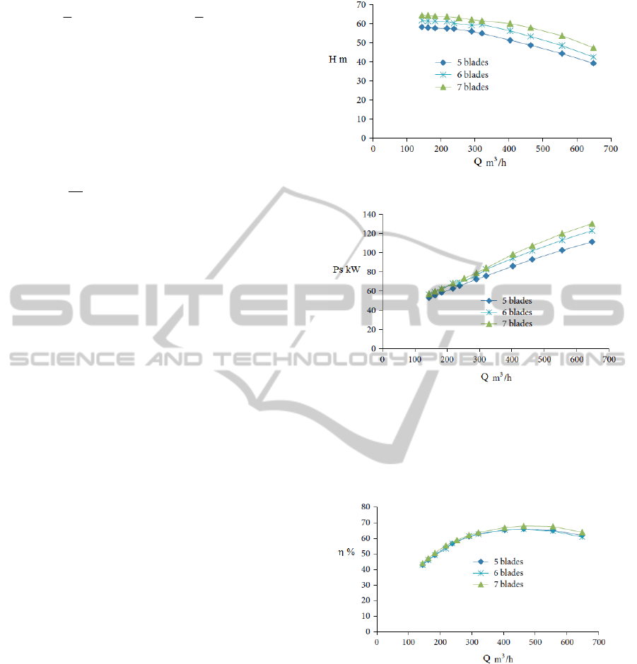
were kept constant. Fig. 4 shows the head as a
function of the volume flow rate, illustrating that the
head and the static pressure keep increasing as the
number of blades increases. Thus, the ideal head is
produced when the number of impeller blades
becomes infinite. Additionally, as shown in Fig. 5,
the brake horsepower increases relative to the
increased number of impeller blades. This is due to
the increase in the request pump shaft torque, as the
number of impeller blades also increases.
Figure 4: Pump stage head versus volume flow rate.
Figure 5: Brake horsepower versus volume flow rate.
Furthermore, Fig. 6 shows the efficiency curves,
showing that the impellers with 5 and 6 blades have
the same efficiency that is lower than the efficiency
for the impeller with 7 blades for large volume flow
rates.
Figure 6: Efficiency versus volume flow rate.
In addition, the distribution of the pressure
difference for Q = 464 m
3
/h in the impeller, diffuser
and diffuser return vane passages is indicated in Tab.
1.
3.2 Impact of the Number of Diffuser
Return Vanes
To investigate the impact that the number of diffuser
return vanes has on the pump stage head, brake
horsepower and efficiency, three diffuser models
NumericalInvestigationofLiquidFlowinTwo-,Three-andFour-StageCentrifugalPumps
95
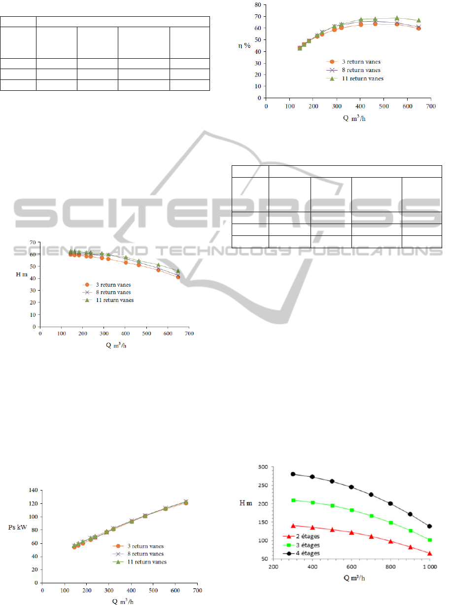
Table 1: Distribution of pressure difference.
Pressure difference ∆p Pa
Blade
number
Impeller Diffuser
Diffuser
return vane
passages
∆p
total
5 476784 98196 -100018 474962
6 512751 108942 -102010 519683
7 547270 120316 -102618 564968
with 3, 8 and 11 return vanes, and 11 vanes were
selected considering an impeller with 6 blades, while
other parameters were kept constant. Fig. 7 shows
the head as a function of the volume flow rate,
where it is observed that the head obtained with the
3 diffuser return vanes is the lowest. This can be
explained by the fact that the variation in the number
of diffuser return vanes affects flow loss due to flow
guidance and friction loss in diffuser return vanes.
As depicted in Fig. 8, the brake horsepower is only
slightly affected by the number of diffuser return
vanes.
Figure 7: Pump head versus volume flow rate.
Furthermore, Fig. 9 shows that for higher volume
flow rates, the efficiency of the diffuser with 11
return vanes is highest. This figure also indicates
that the efficiency is lowest for 5 diffuser vanes.
Additionally, Tab. 2 indicates the pressure
difference in the impeller, diffuser and diffuser
return vane passages, where it can be observed that
the highest pressure loss in the diffuser with 3 return
vanes.
Figure 8: Brake horsepower versus volume flow rate.
Figure 9: Efficiency versus volume flow rate.
Table 2: Distribution of pressure difference.
Pressure difference ∆p Pa
Return
vane
number
Impeller Diffuser
Diffuser
return vane
passages
∆p
total
3 517349 103444 -122147 498646
8 512751 108942 -102010 519683
11 516752 107500 -92048 532204
3.3 Impact of the Number of Stages
To analyze the impact that the pump stage number
has on the pump head, brake horsepower and
efficiency, three centrifugal pumps with 2, 3, 4
stages were selected, while the other parameters
were kept constant. Fig. 10 represents the head as a
function of the volume flow rate, illustrating that the
pump head increases as the number of centrifugal
pump stages increases.
Moreover, as shown in Fig. 11, the brake
horsepower increases relative to the increased
number of centrifugal pump stages. This is due to
the increase in the request pump shaft torque, as the
number of centrifugal pump stages increases.
Furthermore, Fig. 12 indicates that the increase
of the number of centrifugal pump stages does not
nearly affect the pump efficiency.
Figure 10: Pump stage head versus volume flow rate.
SIMULTECH2014-4thInternationalConferenceonSimulationandModelingMethodologies,Technologiesand
Applications
96
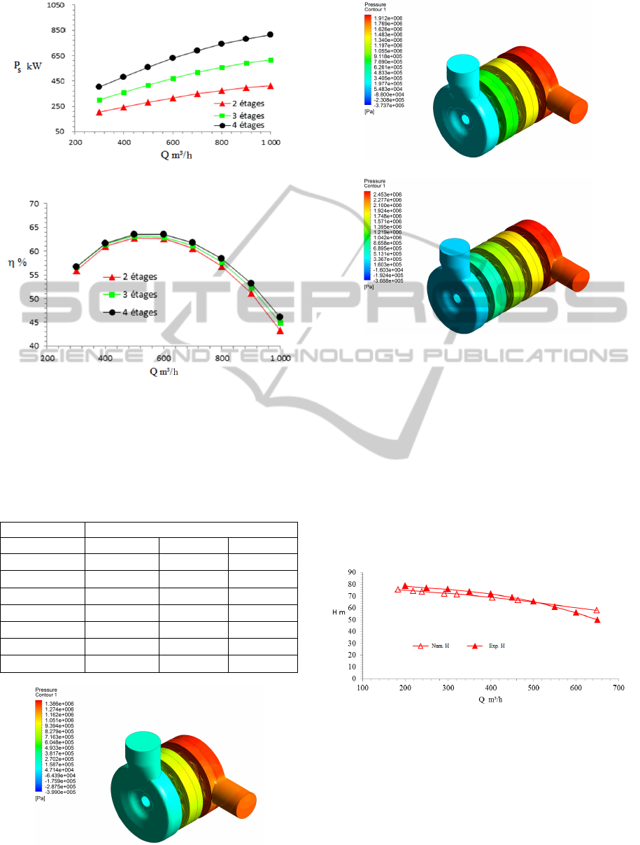
Figure 11: Brake horsepower versus volume flow rate.
Figure 12: Efficiency versus volume flow rate.
In addition, Fig. 13 represents the corresponding
contours for static pressure. There, it can be seen
that the static pressure increases with increasing the
pump stage number as depicted in Tab. 3
Table 3: Distribution of pressure difference ∆p [Pa].
Number of stages
2 3 4
Suction
‐45616 ‐45731 ‐45850
Stage # 1 575385 570477 570527
Stage # 2
638616 559292 556666
Stage # 3 -
634570 556320
Stage # 4 - - 637700
Discharge
‐87020 ‐89690 ‐89090
Δp
total
1081365 1628918 2186273
a) 2-stage centrifugal pump
b) 3-stage centrifugal pump
c) 4-stage centrifugal pump
Figure 13: Static pressure contour
3.4 Model Validation
To validate the model developed for the multistage
centrifugal pump, the numerical simulation results
were compared with the experimental results
obtained from Technosub for a first stage. Figs. 14-
16 show the comparison between the experimental
and numerical curves for the head, brake horsepower
and efficiency, respectively. From these figures, it
can be seen that there is good harmony between the
numerical and experimental results.
Figure 14: Pump stage head versus volume flow rate.
4 CONCLUSIONS
In this work, a steady state liquid flow in a two-,
three- and four-stage centrifugal pumps was
numerically investigated. A model of a centrifugal
pump stage composed of an impeller, diffuser and
casting was developed to analyze the impacts of the
NumericalInvestigationofLiquidFlowinTwo-,Three-andFour-StageCentrifugalPumps
97
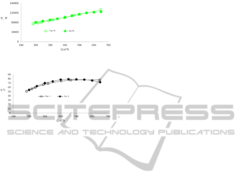
Figure 15: Pump stage brake horsepower versus volume
flow rate.
Figure 16: Pump stage efficiency versus volume flow rate.
number of impeller blades, diffuser return vanes and
stage on the head, brake horsepower and efficiency
of the pump. The results obtained demonstrate,
among other things, that the pump stage head and
brake horsepower increase as the number of impeller
blades increases. Furthermore, the head and
efficiency increase for large volume flow rates with
increasing numbers of the diffuser return vanes. The
brake horsepower hardly varies at all regardless of
the number of diffuser return vanes. Additionally,
the results obtained clearly reveal that the head and
brake horsepower of a multistage centrifugal pump
increase as the number of the stage increases. The
efficient is less affected by the pump stage number.
The comparison of the developed model with the
experimental results shows good agreement.
NOMENCLATURE
B source term (Nm
-3
)
C torque (Nm)
g acceleration of gravity (ms
-2
)
H head (m)
P power (W)
p pressure (Nm
-2
)
p
turbulence production due to viscous and
buoyancy forces
Q flow rate (m
3
s
-1
)
r radial coordinate (m)
V velocity (ms
-1
)
u flow velocity in x direction (ms
-1
)
v flow velocity in y direction (ms
-1
)
w flow velocity in z direction (ms
-1
)
x x-coordinate (m)
y y-coordinate (m)
z z-coordinate (m)
Greek symbols
difference
turbulence dissipation (m
2
s
-3
),
efficiency
turbulence kinetic energy (kg m
-2
s
-2
)
fluid density (kg m
-3
)
dynamic viscosity (Pa s)
eff
effective viscosity (Pa s)
t
turbulence viscosity (Pa s)
ω angular velocity (rad s
-1
)
Subscripts
1 inlet
2 outlet
h hydraulic
i inlet
m mechanical
o outlet
s shaft
t total
v volumetric
vel velocity
ACKNOWLEDGMENTS
The authors are grateful to the Foundation of
University of Quebec in Abitibi-Temiscamingue
(FUQAT) and the company Technosub inc.
REFERENCES
Peng W. 2008. Fundamentals of turbomachinery.
Hoboken, New Jersey, John Wiley and Sons.
Huang S., Islam M. F., Liu P. 2006. Numerical simulation
of 3 D turbulent flow through an entire stage in a
multistage centrifugal pump. International Journal of
Computational Fluid Dynamics, Vol. 20, Issue 5,
Pages 309-314.
Miyano M., Kanemoto T., Kawashima D., Wada A., Hara
T., Sakoda K. 2008. Return Vane Installed in
Multistage Centrifugal Pump. International Journal of
Fluid Machinery and Systems, Vol. 1, No. 1.
SIMULTECH2014-4thInternationalConferenceonSimulationandModelingMethodologies,Technologiesand
Applications
98

Kawashima D., Kanemoto T., Sakoda K., Wada A., Hara
T. 2008. Matching Diffuser Vane with Return Vane
Installed in Multistage Centrifugal Pump.
International Journal of Fluid Machinery and
Systems, Vol. 1, No. 1.
Gantar M., Florjancic D., and Sirok B. 2002. Hydraulic
Axial Thrust in Multistage Pumps - Origins and
Solutions. Journal Fluids Engineering, Vol. 124, Issue
2, 336-341.
Jirout T. 2014. Pumping capacity of pitched blade multi-
stage impellers. Chemical and Process Engineering,
35 (1), 47-53.
Nicolas La Roche-Carrier N., Dituba Ngoma G., and Ghie
W. 2013. Numerical investigation of a first stage of a
multistage centrifugal pump: impeller, diffuser with
return vanes, and casing. ISRN Mechanical
Engineering, Volume 2013, Article ID 578072, 15
pages.
Ansys inc. 2011. ANSYS-CFX (CFX Introduction, CFX
Reference Guide, CFX Tutorials, CFX-Pre User's
Guide, CFX-Solver Manager User's Guide, CFX-
Solver Modeling Guide, CFX-Solver Theory Guide),
release 14.0, USA.
Technosub Inc., www.technosub.net.
NumericalInvestigationofLiquidFlowinTwo-,Three-andFour-StageCentrifugalPumps
99
