
Flexible Shape Measurement System for Chemical Plant Using
Magnetic Sensors
Kumiko Yoshida
1
and Kikuhito Kawasue
2
1
Interdisciplinary Graduate School of Agriculture and Engineering, University of Miyazaki, 1-1 Gakuen Kibanadai Nishi,
Miyazaki, Japan
2
Department of Environmental Robotics, University of Miyazaki, 1-1Gakuen Kibanadai Nishi, Miyazaki, Japan
Keywords: Computer Vision, Pipe Measurement, Magnetic Sensor, CCD Camera, Point Cloud.
Abstract: We propose a flexible computer vision system using magnetic sensors. The system enables a flexible free
scanning of a CCD camera and a laser slit using 3D magnetic sensors. Many numbers of views of each
model from different angles can be taken on measuring the configuration between a CCD camera and a laser
slit projector simultaneously. The information of different views is combined to reconstruct the 3D object
on a computer display. In this paper, the application for pipe measurement is introduced. Experimental
results show the feasibility of our system.
1 INTRODUCTION
Replacement or construction of new pipes is often
carried out for the renewal of the superannuated
facilities in a chemical plant and general factory.
Generally, as the facilities in the plant are running
continuously, the period of the replacement work
should be minimum time to keep the productivity. In
order to cope with this requirement, detailed and
exact data (drawing) of the pipe arrangements are
indispensable. However, almost all drawings do not
correctly match with the state of current pipe
arrangements in the factory. Therefore, the re-
measurement of the pipes is required frequently at
the plant. Generally, the re-measurement is
conducted by manually using a metal tape measure
etc. and it causes the redo of the replacement or
construction works since the accuracy of the manual
measurement is uncertain.
Recently, the three-dimensional measurement
systems with a laser scanner are widely used in
various fields (Faugeras, 1996; Ochiai, 1988; Torras,
1992). These systems have begun to be utilized also
for the equipment measurement in chemical plants.
The measurement system can obtain thousands of
point cloud data with three-dimensional position in a
few second. Point cloud data are sets of vertices in a
three-dimensional coordinate system. The point
cloud data are useful for the fundamental data to
grasp the situation of the facilities in the plant. In the
typical measurement system with a laser scanner, an
infrared laser is sent out and reflected back to the
system. The distance is measured by the time of
flight of the laser pulse between the device and
target, or the shift in the wavelength of the return
beam(Pueschel, 2013). However, since these laser
scanners are generally fixed on the stable ground
with a tripod, the setting position is restricted and
the unmeasurable area are existed such as the narrow
or pipes crowded area etc. These areas have to be
measured by conventional way using metal measure
etc. Therefore hand held measurement system for
the measurement in such a crowded area has been
required.
In this paper, hand held measuring system using
magnetic sensors is introduced. This system is based
on the slit-ray projection method. Slit-ray is
projected on the surface of an object and the
reflected light is recorded by a CCD camera. Three-
dimensional position on the slit is calculated on
considering the configuration of the CCD and the
laser projector. Proposed system with magnetic
sensors enables us a separated free scanning of each
of a CCD camera and a laser slit projector. The
magnetic receiver (Polhemus Inc.) is attached in
each of a CCD camera and a laser projector. The
magnetic transmitter is placed on the fixed table and
the magnetic fields are generated from the
transmitter. The magnetic receiver detects the each
three-dimensional position and the orientation of the
758
Yoshida K. and Kawasue K..
Flexible Shape Measurement System for Chemical Plant Using Magnetic Sensors.
DOI: 10.5220/0005097707580763
In Proceedings of the 11th International Conference on Informatics in Control, Automation and Robotics (ICINCO-2014), pages 758-763
ISBN: 978-989-758-039-0
Copyright
c
2014 SCITEPRESS (Science and Technology Publications, Lda.)
CCD camera and the laser projector at 60Hz on
considering the received magnetic strength and
direction. Many numbers of views of a model from
different orientations are taken on measuring the
configuration between a CCD camera and laser-slit
simultaneously. User directs the laser on the
measuring target and the CCD detects the image
from the position where the reflected light is visible.
It enables the flexible measurement for a complex
area. The information of different views can be
combined to reconstruct the 3D object on a
computer display with minimum loss of data.
For one of the applications of our system, the
shape measurement of pipes is introduced in this
paper. The proposed system was applied to measure
the shape and arrangements of pipes. Furthermore,
3D temperature measurement is introduced for one
of the application of our system. Experimental
results show the feasibility of our system.
2 SYSTEM SETTING
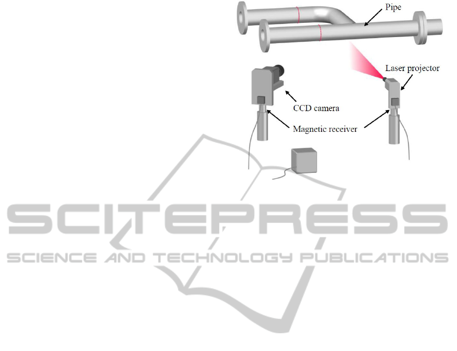
Figure 1 shows the setup of the measurement
system. The system consists of a CCD camera, slit
laser projector. Electric magnetic receiver is attached
on each of the CCD camera and the slit laser
projector. The magnetic transmitter is placed on the
fixed table near the magnetic receivers. A slit ray is
projected on the surface of the measuring object and
the CCD camera records the reflected light that
appears on the surface of the object. The transmitter
of the electro-magnetic sensor generates the
magnetic field and the magnetic field is detected by
the each of the magnetic receiver. The signal from
the magnetic receiver is sent to the main controller
to calculate the three-dimensional position and the
orientation (Azimuth, Elevation, Roll) of the
receiver. (McCallum, 1996, 1998; Nixon, 1998).
The positions and the direction of the CCD
camera and the laser projector are detected at a rate
of 60 Hz during the measurement; therefore, it
enables the flexible measurement by a free scanning
of the CCD camera and the laser.
3 MEASUREMENT PROCEDURE
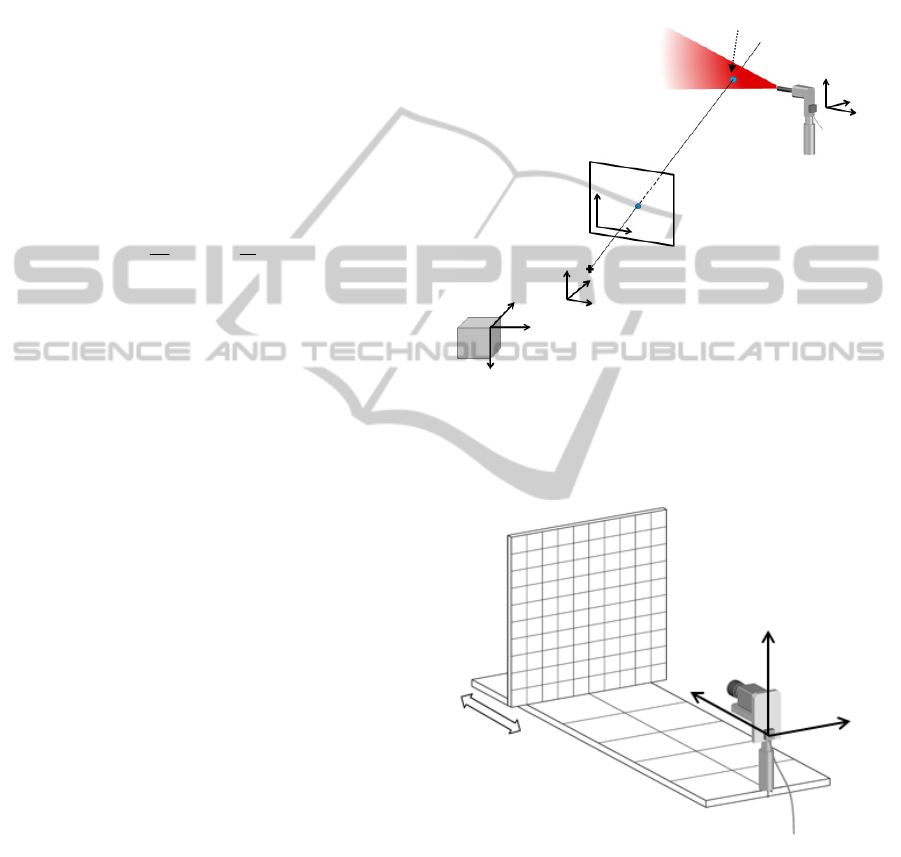
The relation between the camera coordinates and the
receiver coordinates is shown in Figure 2. The
measurement procedure is to estimate the
intersection between the laser plane and the vector
from the focal point F of the CCD camera. The laser
Figure 1: Setup of the measuring system.
plane and vector from the focal point of the CCD
camera is detected on real time during the
measurement by the magnetic sensors.
The electro-magnetic sensor receiver attached on
the laser slit projector enables the real-time detection
of laser plane information. The information detected
by the magnetic receiver is the three-dimensional
position (x
ow,
y
ow,
z
ow
) and the orientation (Ψ:
Azimuth, Θ: Elevation, Φ: Roll) of the magnetic
receiver itself. This information is used to determine
the equation of the laser plane. The arbitrary three
points on a laser plane on receiver coordinates
originated at the receiver position are converted into
the world coordinates (x
rw
, y
rw
, z
rw
) originated at the
transmitter position by the following formula.
ow
ow
ow
r
r
r
rw
rw
rw
z
y
x
z
y
x
RPY
z
y
x
,,
(1)
where
CCSCS
SCSSSCCSSSCS
SSCSCCSSSCCC
CS
SC
CS
SC
CS
SC
RPY
0
0
001
0
010
0
100
0
0
,,
C: Cos., S: Sin.
Ψ: Azimuth, Θ: Elevation, Φ: Roll
Three arbitrary three points on a laser plane are
converted to world coordinates originated at the
transmitter position by (1) and the laser plane
equation is determined on the world coordinates as
FlexibleShapeMeasurementSystemforChemicalPlantUsingMagneticSensors
759
following equation.
1
1
1
,,
C
B
A
zyx
(2)
where
1
1
1
1
333
222
111
rwrwrw
rwrwrw
rwrwrw
zyx
zyx
zyx
C
B
A
The detection process of the laser plane
information is executed at 60Hz. The point appeared
on the image plane is explained by using the camera
coordinates with an origin at focal point as following.
Z
Y
fv
Z
X
fu ,
(3)
This relation can be expressed by matrix as
following.
Z
Y
X
f
f
v
u
100
00
00
1
(4)
In order to convert this camera coordinates into
the receiver coordinates with an origin at the
receiver, parameters (k
11
-k
33
) are introduced on
considering the rotation and displacement as
following.
1
11
333231
24232221
14131211
z
y
x
kkk
kkkk
kkkk
v
u
s
(5)
Equation (5) indicates the relation between the
camera coordinates and the receiver coordinates.
This equation can be converted also as following.
vkzkvkykvkxkvk
ukzkukykukxkuk
24233322322131
14133312321131
(6)
The eleven parameters k
11
-k
33
can be determined
by setting some corresponding coordinates that the
values are already known. The calibration setup is
shown in Figure 3. The image of the scale board is
recorded by the CCD camera and is displayed on the
computer display. A mouse device and a keyboard
set the camera coordinates and the receiver
coordinates, respectively.
The equation (6) indicates the two planes. The
intersectional line between these planes indicates the
line from the focal point F to the measuring point on
the receiver coordinates. The line can be expressed
with an extra parameter t as following.
lthz
ntgy
mtfx
(7)
Figure 2: Relation between camera coordinates and
receiver coordinates.
Figure 3: Calibration setup.
where (f,g,t) is a vector that the direction is from
focal point of the camera to the measuring point and
(m,n,l) is a point located on the line on the receiver
coordinates. This receiver coordinates can be
converted to the world coordinates with an origin at
the transmitter as following formula.
x
y
z
Scale board
CCD camera
with magnetic sensor
Measuring point
x
r2
z
r2
y
r2
Laser plane
Receiver coordinate
Image plane
x
r1
z
r1
y
r1
X
Y
Z
Receiver coordinate
World coordinate
v
u
Camera coordinate
Camera focus F
ICINCO2014-11thInternationalConferenceonInformaticsinControl,AutomationandRobotics
760
z
y
x
w
w
w
lth
ntg
mtf
RPY
Z
Y
X
,,
(8)
Where RPY is an orientation of the receiver and
(w
x
, w
y
, w
z
) indicates the position of the receiver.
The position of measuring point on the world
coordinates can be determined as the intersection
between the laser plane and the line from focal point
of the CCD camera to measuring point. The position
(X, Y, Z) can be calculated from (2) and (8). It is
rearranged as following.
z
y
x
wRPYl
wRPYn
wRPYm
t
Z
Y
X
RPYh
RPYg
RPYf
CBA
,,
,,
,,
1
,,100
,,010
,,001
0
(9)
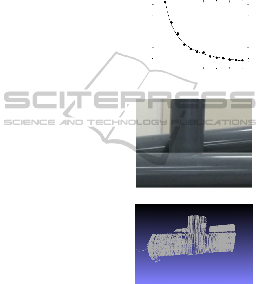
4 EXPERIMENTS
Since the system is based on the principle of
triangulation, the angle between the CCD camera
and the laser slit influences the measurement
accuracy. Therefore, in this experiment, the angle
between the CCD and the laser slit was changed by
5 degree, and the accuracy of the measurement was
evaluated. Figure 4 shows the example of the
measurement accuracy in this experiment when a
plane board was set at distance 426 mm from the
CCD. The results of the measured positions were
evaluated at the known position on the plane board
on each angle between the CCD camera and the
laser. When the angle between the CCD camera and
the laser slit was over 20 degree, the error was less
than 1 mm.
In the measurement using our proposed system,
an operator projects the laser slit on the target and
the slit ray reflected on the surface of the target is
recorded by the CCD camera from the angle where
the slit ray is visible. CCD camera and laser
projected can be moved separately and it enables us
the flexible measurement. The pipe can be
reconstructed from more than two sets of the cross-
sectional point cloud data. The photograph of
measured pipes is shown Figure 5. They are made of
plastic and the diameters are 114 mm. Figure 6
shows the point cloud data obtained by our system
and Figure 7 shows the reconstructed pipe from the
point cloud data.
20 40
60
1
2
3
0
Angle between CCD camera and Slit ray [deg]
Measured erro
r
[mm]
z=426[mm]
Figure 4: Measurement accuracy.
Figure 5: Photograph of measured pipes.
Figure 6: Point cloud data of measured pipes.
The three-dimensional temperature distribution can
be measured using thermography attached on our
system (Li, 2013). Figure 8 shows the three-
dimensional temperature measurement system. In
order to allocate the temperature data into the 3D
FlexibleShapeMeasurementSystemforChemicalPlantUsingMagneticSensors
761
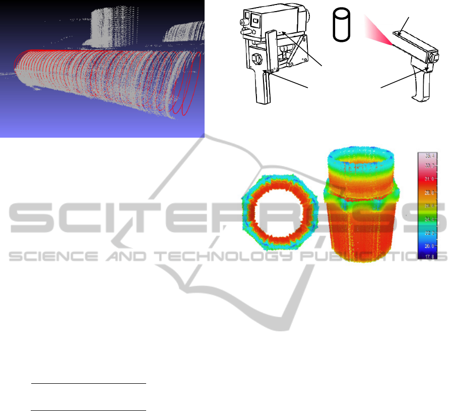
Figure 7: Reconstructed pipe from the point cloud data.
shape data, it is necessary to calibrate the
thermography since the corresponding position
relationship between thermography coordinates and
world coordinates need to determine in advance. The
relationship between thermography coordinates (u
t
,
v
t
) and world coordinates (x,y,z) is formulated as
follows.
1
11
12
13
14
21
22
23
24
31
32
33
1
∙
1
(10)
Where, it is called as thermography calibration
that estimates the parameters (h
11
to h
33
). These
parameters can be determined by inputting some
corresponding coordinates between the
thermography coordinates and the world coordinates.
Equation (11) can be written as follows.
11
12
13
14
31
32
33
1
21
22
23
24
31
32
33
1
(11)
Once parameters h
11
to h
33
and world coordinates
of measurement points on the surface of a target
object are determined, the corresponding
thermography coordinates can be calculated by
equation (11). Therefore, the corresponding
temperature data can be allocated to the
reconstructed shape of a target object. Figure 9
shows the reconstructed three-dimensional shape
with temperature of a plastic pipe.
5 CONCLUSION
Three-dimensional measurement system which
enables a separated free scanning of a CCD camera
and a laser slit has been introduced. An operator can
change the configuration flexibly between a CCD
Figure 8: Three-dimensional temperature measurement
system.
Figure 9: Reconstructed three-dimensional shape with
temperature.
camera and a laser slit according to the complexity
of the target. It should take a larger angle between a
laser and camera for a smooth area, and smaller
angle for a complicated area. Since the angle
between the CCD camera and the laser influences
the measurement accuracy during the measurement,
the result depends on the operator’s experience. It is
desirable to record the reliability on a measurement
result with digital data.
For one of the applications of our system, the
shape measurement of pipes is introduced in this
paper. The proposed system was applied to measure
the shape and arrangements of pipes. Furthermore,
3D temperature measurement is introduced for one
of the application of our system. Experimental
results show the feasibility of our system.
REFERENCES
Faugeras, O., 1996. Three-dimensional computer vision, A
geometric viewpoint. Cambridge, MA: MIT Press.
Li, T. and Kawasue, K., 2013. Calibration Methods for 3D
Thermo-sensing System. Information Technology
Journal, 12(24), 8424-8429.
McCallum, B. C., Fright, W. R., Nixon, M. A. and Price,
N. B., 1996. A Feasibility Study of Hand-held Laser
Magnetic receive
r
Thermography
Laser projecto
r
ICINCO2014-11thInternationalConferenceonInformaticsinControl,AutomationandRobotics
762

Surface Scanning. in: Proceedings of Image and
Vision Computing NZ 1996, Lower Hutt, 103–108.
McCallum, B. C., Nixon, M. A., Price, N. B. and Fright,
W. R., 1998. Hand-held Laser Scanning, in:
Proceedings of Image and Vision Computing NZ 1998,
The University of Auckland, 17–22.
Nixon, M. A., McCallum, B. C., Fright, W. R. and Price,
N.B., 1998. The Effects of Metals and Interfering
Fields on Electromagnetic Trackers. Presence, MIT
Press, 7(2), 204-218.
Ochiai, T., Ishimatsu, T., Kawasue, K., Fukakawa, M. and
Kumon, K., 1988. three-dimensional surface
measurement of a human face. Industrial Electronics
Society, 4, 965 – 970.
Pueschel, P., 2013. The influence of scanner parameters
on the extraction of tree metrics from faro photon 120
terrestrial laser scans. PandRs, (78), 58–68.
Torras, C., 1992. Computer vision : theory and industrial
applications. Berlin ; New York: Springer-Verlag.
FlexibleShapeMeasurementSystemforChemicalPlantUsingMagneticSensors
763
