
An Architecture for the Design of Platforms Supporting Responsive
Environments
Marco Covelli
1
, Daniela Micucci
2
and Marco Mobilio
2
1
TabulaeX, via Carducci 32, Milan, Italy
2
Department of Informatics Systems and Communication, University of Milano Bicocca, Viale Sarca 336, Milan, Italy
Keywords:
Perception Flow, Action Flow, Integration, Software Architecture, Responsive Environments
Abstract:
Responsive environments are able to sense the environment and to respond to it and to the users that inhabit
it. Those systems require both the integration of heterogeneous devices and an abstract representation of
the environment to reason about interesting changes. The paper presents DEA (Domain Entities Access), an
architecture that enables the realization of platforms supporting responsive environments in the interaction
with instrumented physical environments through the observation and the control of meaningful domain en-
tities, thus abstracting from any technological details. Platforms can be easily realized by plugging specific
domain-dependant components in a framework that manages all the domain-independent aspects. Thus, the
architecture results to be open with respect to both new devices and new typologies of domain entities. A
prototypical implementation of the framework has been provided. Moreover, a specific platform has been
realized to support an end-user application dealing with instrumented environments.
1 INTRODUCTION
Instrumented environments (Butz and Kr
¨
uger, 2003)
are common environments enriched with devices able
to gather information about them and to act on them.
From a technological point of view, they constitute
the milestone of the responsive environments (Negro-
ponte, 1975; Bullivant, 2006), systems able to sense
the environment and to respond to it and to the users
that inhabit it.
Those kind of systems primarily require to in-
termix multiple components and integrated solutions
(e.g., home automation gateways) that are highly het-
erogeneous, have different capabilities, and often rely
on different communication protocols (Kim et al.,
2012). Due to this heterogeneity, many systems rely
on ad hoc solutions that often are based on specific
technologies and protocols.
The approaches to the integration of heteroge-
neous devices can be divided into two main groups:
solutions that supply with enabling integration plat-
forms (Thomson et al., 2008; Kusznir and Cook,
2010; Ristau, 2008), and solutions that provide plat-
forms that allow applications to reason in terms of
domain-related concepts (Rom
´
an et al., 2002; Aiello
and Dustdar, 2008). Platforms of the first group pro-
vide an unified access to the heterogeneous devices.
Thus, they can be used in any application domain, but
they do not provide an abstract, domain-dependant
model of the environment. On the opposite, solu-
tions of the second group provide applications with
a model of the environment that is closer to the appli-
cation logic, thus filling the gap between the physical
environment and how it is perceived by the applica-
tions. The main disadvantage of such solutions con-
cerns the poor adaptability of the model to different
domains than the original.
The paper proposes Domain Entities Access
(DEA), an architecture for the observation and the
control of instrumented environments that is located
halfway between the two main classes of approaches.
DEA allows the integration of heterogeneous devices
and provides end-user applications with a unified ac-
cess to an abstract domain-related representation of
the environment. The abstract representation of the
environment i) captures domain related issues by ab-
stracting from the physical devices; ii) can be in-
spected by end-user applications with the aim of iden-
tifying intelligent/ad hoc behavior; and iii) can be
used by end-user applications to deliver commands
reifying the identified intelligent/ad hoc behavior.
The architecture carefully separate issues related
to the specific application domain (e.g., inferring the
position of a person from stimuli generated by a cam-
417
Covelli M., Micucci D. and Mobilio M..
An Architecture for the Design of Platforms Supporting Responsive Environments.
DOI: 10.5220/0005099404170427
In Proceedings of the 9th International Conference on Software Engineering and Applications (ICSOFT-EA-2014), pages 417-427
ISBN: 978-989-758-036-9
Copyright
c
2014 SCITEPRESS (Science and Technology Publications, Lda.)

era) from those that are domain-independent (e.g.,
the way applications observe and control the environ-
ment). Moreover, the architecture enforces the insu-
lation and compactness of components, and, in par-
ticular, of those that are domain-dependant. Such
an approach allows defining a framework that pro-
vides both an implementation of all the domain-
independent and the infrastructure in which easily
plugging the domain-dependant components. This re-
sults in a platform that end-user applications can ex-
ploit to observe and control domain-related entities.
The paper is organized as follows: Section 2
presents the DEA architecture; Section 3 describes
the implementation of a framework supporting the
DEA architecture and a specific configuration for a
real simplified scenario; Section 4 compares DEA to
the state of the art; and Section 5 outlines the conclu-
sions and identifies future directions.
2 DEA ARCHITECTURE
There is a semantic gap between the environment
model used by end-user applications to observe and
interact with the physical environment and the de-
vices that produce stimuli and actuate actions. End-
user applications reason in terms of statuses of do-
main entities. For example, “Marco is located in
room 27”, “switch on the main light in room 2006”.
All the emphasized words are domain entities and
related statuses. On the opposite, sensing devices
produce stimuli and actuating devices accept actions
whose semantics and syntax is up to the devices.
“DF6YH78KLO”, “#01001#01”, are respectively ex-
amples of a stimulus from a RFID reader and of an
action to a BTicino light.
DEA (Domain Entity Access) is a layered archi-
tecture for the design of platforms supporting end-
user applications that reason in terms of domain en-
tities be they abstractions of physical devices (e.g.,
lamp) or inferred from events generated by sensing
devices (e.g., people), thus filling the semantic gap.
The architecture seamlessly integrates sensing and ac-
tuation devices, providing end-user applications with
a environment model that they can exploit to control
and observe the status of meaningful domain entities.
The environment model is an abstract and unified rep-
resentation of the context of interest, which ranges
from the physical devices (e.g., lamps) to the people
that inhabit the environment.
2.1 Overview
Stimuli from the sensing devices in the physical en-
vironment contribute in maintaining the environment
model updated so that it can reflect the “real” situa-
tion. Symmetrically, commands from end-user appli-
cations possibly affect the “real” environment through
actions that are performed by actuating devices. In
turn, a change of the “real” environment is captured
by sensing devices that produce stimuli, thus closing
the loop. For example, an application that tracks peo-
ple and activates cameras only when required, rea-
sons on a model of the environment constituted by
people and cameras whose status is updated by a set
of physical cameras, RFID readers, and any kind of
sensing device able to detect movements. Moreover,
the application operates on the status of the camera in
the environment model to control the corresponding
physical camera, thus ignoring the specific techno-
logical dependant action required to switch on/off the
physical camera. In turn, when the physical camera
changes its status, the corresponding generated stim-
ulus will update the status of the camera in the en-
vironment model. The two flows respectively realize
the processes of perception and action described in
(Cook and Das, 2007).
Referring to Figure 1, the first three layers of the
architecture (from the bottom) deal with data abstrac-
tion that is responsible for maintaining the environ-
ment model updated with respect to the “real” envi-
ronment, thus managing both the perception and the
action flows. The upper layer deals with access mech-
anisms end-user applications can use to observe and
control the environment model. In detail, the inter-
face layer is responsible for interfacing with the spe-
cific device; the translation layer translates stimuli as
produced by the devices into a common vocabulary
(abstract stimuli) and actions (abstract actions) into
technological dependant actions; the inference/reifi-
cation layer makes inferences about statuses of do-
main entities according to stimuli from the devices
(and the actual statuses) and reifies commands into
abstract actions (independent from any technological
issues) that actuators has to perform; finally, the ac-
cess layer provides mechanisms an end-user applica-
tion can exploit to observe and control statuses of do-
main entities.
2.2 Data Abstraction
The two lowest layers of the architecture concern the
interfacing with a set of heterogeneous devices, each
of them communicating through its own protocol and
producing or consuming data according to its own
ICSOFT-EA2014-9thInternationalConferenceonSoftwareEngineeringandApplications
418
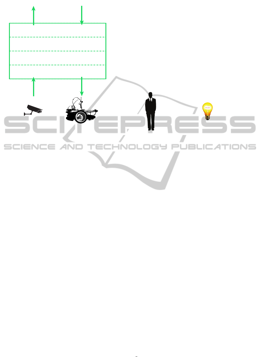
APPLICATIONS
Stimuli
Actions
Statuses
Commands
Access Layer
Interface Layer
Inference / Reification Layer
Translation Layer
Figure 1: Overall architecture.
specific syntax.
The interface layer handles the specific communi-
cation mechanisms with sensors and actuators. Re-
spectively i) it receives stimuli from sensing devices
and delivers them to the translation layer, and ii) it ac-
cepts actions from the translation layer and delivers
them to the correct actuating devices.
At this layer, stimuli are still related to a specific
syntax: the translation layer abstracts from the spe-
cific syntax of stimuli, allowing the higher layer to
focus on their semantics only. Respectively, i) it re-
ceives stimuli from the interface layer, turns their syn-
tax to a common language maintaining the original
semantics by generating abstract stimuli, and deliv-
ers the abstract stimuli to the inference/reifying layer;
ii) it receives abstract actions (i.e., actions expressed
in the common language) from the inference/reifying
layer, generates actions by turning the abstract ac-
tions in the specific syntax known by the actuators
recipients of the actions, and delivers the actions to
the interface layer. This way, the inference/reifying
layer can rely on data (abstract stimuli and abstract ac-
tions) that are completely independent from their spe-
cific devices. For example, in this layer two stimuli
of brightness respectively from a PWM (pulse-width
modulation) and a serial interface, will be standard-
ized to a common scale and syntax.
Stimuli and actions are completely independent
from their specific devices. The inference/reification
layer relies on those information to infer the statuses
of domain entities and to reify commands into actions.
Domain entities (“entities” from now on) realize
the environment model. They are observable and pos-
sibly controllable units of interest in a “real” environ-
ment from the application point of view. An entity is
defined as a set of property-value pairs, that entirely
describes the entity itself. Each property models a
piece of information. Which properties characterize
an entity is a domain related issue. For this reason,
DEA specifies only how they have to be defined. Re-
ferring to a domotic domain, Figure 2 sketches two
examples of domain entities that respectively repre-
sent a person and a light each characterized by its
proper set of properties: a person has a position and
a name, a light has a position too and is in an on/off
status. Moreover, both the entities has a type and an
unique identifier.
Id: m_covelli
Type: Person
Name: Marco Covelli
Location: sal1
Id: light5
Type: Light
Location: sal1
OnOStatus:
On
Figure 2: Examples of domain entities.
Properties can be mutable and immutable. The
former are fixed and cannot be changed over time
(e.g., the name of a person). On the opposite, the
values of mutable properties are the results of a in-
ference process operated in the inference/reification
layer. The process evaluates abstract stimuli from
the translator layer to infer significant changes of do-
main entities properties. In real cases, abstract stimuli
could be inaccurate, mostly due to sensors quality or
intrinsic difficulty of the perception task. For this rea-
son, the inferred values are enriched with confidences.
Thus, stimuli from the field activate perception flows
that cause updates of the statuses of domain entities.
Commands are requests for changing the status of
entities. This means that a status can also be control-
lable. It is important to notice that not all statuses can
be also controllable: although the on/off status of a
light is typically controllable, the same cannot be as-
serted for a person’s location. When a commands is
delivered to the inference/reification layer, it is rei-
fied into abstract actions that are then delivered to
the translator layer. Thus, commands activate action
flows that cause the activation of the physical actua-
tors.
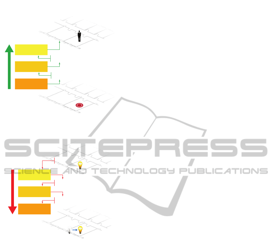
Figure 3 sketches an example of the perception
flow. An RFID sensor detects a tag: this event is
captured by the interface layer that exposes the data
to the upper layer. The data is translated into the
homogeneous syntax and propagated to upper layer.
The inference/reification layer infers the new value
for the position property of the person with identifier
m covelli and then updates the persistent represen-
tation of the environment model.
AnArchitecturefortheDesignofPlatformsSupportingResponsiveEnvironments
419
rd_reader1
data$300833B2DDD9BD0100162B2B#
Interface Layer
Translation Layer
rd_reader1
tagDetection:
300833B2DDD9BD0100162B2B
Inference/Reication
Layer
Id: m_covelli
Location: sal1
Figure 3: Perception flow.
Figure 4 sketches an example of the action flow.
An end-user application wishes to turn a light on. The
light_switcher5
*1*1*5#
light_switcher5
SwitchOn
Id: light5
OnOStatus:On
Interface Layer
Translation Layer
Inference/Reication
Layer
Figure 4: Action flow.
light is modeled by a domain entity with a set of prop-
erties including OnOffStatus, which is controllable
and contains the status of the light. The application
delivers to the inference/reification layer a command
stating that the value of the property OnOffStatus
should be set to On. The layer is in charge of reifying
the command by producing the proper abstract action
for the corresponding light switcher. The abstract ac-
tion is delivered to the translator layer that produces
an action that is understandable to the recipient light
switcher. The action is then managed by the interface
layer that finally deals with the concrete interfacing
with the device.
2.3 Environment Model Access
The inference/reification layer maintains entities (i.e.,
the environment model). The access layer provides
mechanisms end-user applications can exploit to ob-
serve and control the environment model. Such mech-
anisms are based on messages and allow formulat-
ing requests about domain entities without the need to
mention them explicitly. By exploiting a subset of the
concepts of predicate logic, it is possible to refer to
domain entities through their properties and their val-
ues. Such a solution allows end-user applications to
do not explicitly know the domain entities constitut-
ing the environment model. For example, an applica-
tion can formulate a request like “switch on the lamp
in room 27” without explicitly knowing which is the
lamp in room 27. At a conceptual level, the approach
is to send messages directly to domain entities, which
respond individually on their merits. Reply messages
are also characterized by a payload that contains the
required information, and by a sender that identifies
the entity to which the information is referred.
A request message consists of a recipient, which
describes via predicate logic the properties of the enti-
ties to which the message is addressed, and a payload,
which specifies the detail of the request. A reply mes-
sage consists of a sender that is described via predi-
cate logic and a payload with the information related
to the sender.
We define a predicate p(x), with x a domain en-
tity, as a series of property-value couples, linked by
the common logical connectors (conjunction, disjunc-
tion, and negation). For example, the predicate p
1
(x)
“x is a lamp located in sal2 lab” can be expressed in
terms of property-value tokens like “x has property
Type equals to Lamp AND x has property Location
equals to sal2”. Defining the environment model E
as the set of all the domain entities and a given p(x),
it is possible to declaratively describe a set E
p
⊆ E,
containing the entities having the characteristics de-
scribed in p, as follows: E
p
= {e ∈ E | p(e) is true}.
To be fully compliant with the domain model, the syn-
tax includes the possibility to specify a minimum con-
fidence, to filter values under a given trustworthiness
threshold.
This approach effectively allows entity selection
by the specification of property constraints.
The use of predicate enables the definition of dy-
namic sets of entities, by formalizing predicates that
may include mutable property values.
For example, it is possible to define a predicate
p
2
(x) “x is a person in sal2 lab”: there will be a con-
crete possibility that an entity e could be in E
p
at the
moment t
0
but not at t
1
. This makes possible to dis-
criminate entities by their properties, without the need
of enumerating them.
However, it is important to notice that this ap-
proach also fits the case we want to explicitly refer
to a specific entity, that could be done by defining a
constraint on the Id property (if defined).
Exploiting the above described message-based
ICSOFT-EA2014-9thInternationalConferenceonSoftwareEngineeringandApplications
420

protocol, the access layer enables end-user applica-
tions
• to query the model about the punctual status of
selected entities (observation)
• to express interest for statuses’ changes of se-
lected entities, obtaining notifications at each oc-
currence (subscription)
• to express desired statuses for entities, that are rei-
fied in changes to the physical environment made
by suitable actuators (wish)
Observation and subscription are for observation
purposes. However, in the first case the request con-
cerns the current status of an entity; in the second one,
it refers to the status changes that occurs since the re-
quest. Instead, wish allows end-user applications to
deliver commands, i.e., to change the entities status.
For example, observation allows to query the environ-
ment in order to obtain the names of the persons in a
room at the time of the request; subscription allows to
express interest for all the future changes of the status
of the lights in a specific room, without having to ex-
plicitly list them; wish allows to ask for switching off
all the lights in a certain area.
An observation consists in a request message
specifying a predicate that defines the interested enti-
ties and a list L of properties and corresponding values
as payload.
For example, an end-user application needs to
know the number of people that are currently present
in a building composed by two rooms. Room is a do-
main entity characterized by the properties Id (the
identifier), Type (the typology of the entity), and
ContainedPeolple (the number of contained peo-
ple). Thus, the end-user application composes the ob-
servation request message:
Rec ipi e nt :
Type = R oo m
Obse r v a t i o n R e q u e s t :
Co n t a i n e d P e o p le
This message is delivered to all the entities who have
the property Type equals to Room. The payload spec-
ifies that the request concerns the value of their prop-
erty ContainedPeople. The two rooms (sal1 and
sal2) answer the query by sending back to the re-
questing application, the messages:
Sen d e r :
Id = sal1
Ob se rv at io nR es po ns e :
Co n t a i n e d P e o p le = 1 0.9
Sen d e r :
Id = sal2
Ob se rv at io nR es po ns e :
Co n t a i n e d P e o p le = 3 0.9
The second value in ContainedPeople = 1 0.9
and in ContainedPeople = 3 0.9 is the confidence
value.
Subscription allows to observe the environment
model asynchronously: end-user applications sub-
scribe to entity status changes so that they will be
notified each time a change occurs. Firstly the end-
user application performs a subscription specifying
the predicate p that describes the target entities and
the list L of properties in which it is interested. Since
the subscription, the end-user application will receive
a notification whenever a status change involves one
of the properties in L of an entity in E
p
.
For example, an end-user application needs to be
notified each time a student changes its location in-
side a university building. Person is a domain en-
tity characterized by the properties Id (the identifier),
Type (the typology of the entity), Location (the po-
sition inside the building), and Role (the role of the
person). Thus, the end-user application composes the
subscription request message:
Sen d e r :
Ca s e S tu d y A p p
Re c ip i en t :
Type = P e r son A ND
Role = S t u de n t
Su bs cr ip ti on Re qu es t :
Lo c a t i o n
From now on, the requesting application will be
notified of any Location value change that involves
entities of type Person and role Student. Differently
from “standard” request messages, the subscription
also includes a sender field, needed to identify the re-
cipient of future notification messages. Suppose that
the environment model has been updated as a result of
a perception flow generated by an image captured by
a camera. The Location value of the entity with Id
equals to m covelli has changed, meaning that the
entity “has entered” a new location. Then, the entity
itself sends to the applications that are subscribed to
such event the notification message:
Sen d e r :
Id = m _c o ve l li
St a t u sC h a n g e :
Lo c a t i o n = s a l 1 0 .8
Wish allows end-user applications to control the
“real” environment through commands. Actuated
commands can produce effects that are perceived by
sensors, which activate a perception flow. Thus, the
consequences of a command request will be observ-
able by the applications if they properly observe the
environment model, according to the previous intro-
duced modes (observation and/or subscription). In
AnArchitecturefortheDesignofPlatformsSupportingResponsiveEnvironments
421

other words, to perceive the change, the application
must observe the entity it wants to control.
A wish consists in a request message that con-
tains a predicate p that describes the target entities,
and a property-value pair as payload, that specifies the
property and the new value the application “wishes”
to assign to the target entities.
For example, an end-user application needs to
switch on all the lights in the sal1 room. Light
is a domain entity characterized by the properties
Id (the identifier), Type (the typology of the en-
tity), Location (the position inside the building), and
OnOffStatus (the on/off status). Thus, the end-user
application composes the request message:
Re c ip i en t :
Type = Li g h t AN D
Lo c a t i o n = s a l 1
Wi s h R eq u e s t :
On O f f St a t u s = On
This request message selects the entities by the type
(they should be lights) and the location (they should
be in sal1), and asks them to switch on. This request
activates an action flow.
2.4 Concrete Architecture: Components
Figure 5 illustrates the overall architecture with em-
phasis on its concrete realization in terms of software
components.
Each of the first three layers deals with well-
defined data structures both in perception flow (from
bottom to top) and in action flow (from top to bottom).
This allows identifying software components charac-
terized by compactness and insulation (Stevens et al.,
1979).
In detail and starting from the bottom, the compo-
nent in charge of communicating with a device is the
sensor wrapper (for sensing devices) and the actua-
tor wrapper (for actuating devices). At least there are
as many wrappers as the different typologies of the
physical devices. In Figure 5 they are represented by
the components labeled SW
i
(sensor wrappers) and AW
i
(actuator wrappers).
The component in charge of operating translations
is the stimuli translator (from stimuli to abstract stim-
uli) and the action translator (from abstract actions to
actions) respectively. At least there are as many trans-
lators as the different typologies of protocols used by
the physical devices. In Figure 5 components labeled
ST
i
and AT
i
are respectively stimuli translators and ac-
tion translators.
Wrappers and translators depend on the specific
devices that instrument the environment. Thus, they
are domain-dependant components.
The inference and the reification activities in
the inference/reification layer are respectively con-
cretized by the status guesser and the wish reasoner
components.
In Figure 5, components labeled SG
i
and WR
i
are
respectively status guessers and wish reasoners. How
many guessers are needed depends both on the char-
acteristics of the domain entities (i.e., their properties
and dependencies) and on how much the guessers are
compact and insulate. The same holds for the wish
reasoners.
Guessers and reasoners depends on the spe-
cific domain entities that constitute the environment
model and their properties. Thus, they are domain-
dependant components.
Each interaction mode is supported by specific
components as depicted in Figure 5: the observa-
tion component is in charge of managing the obser-
vation interaction mode; the subscription component
is in charge of managing the subscription interaction
mode by capturing the status changes inferred by the
status guessers and delivering them to the subscribed
end-user applications; and the wish component is in
charge of managing the status change requests, thus
delivering them to the proper wish reasoners.
The identified components and layering allow to
define a framework for what concerns the access layer
and the structure of the components in the data ab-
straction layer. When an instrumented environment
must be observed and controlled, then a platform is
designed. Such a platform will relies on the frame-
work for what concerns the domain-independent is-
sues, and will include both the appropriate set of do-
main entities and the domain-dependant components.
3 VALIDATION
The validation aimed to prove the effective advan-
tages in the development of end-user applications us-
ing the presented architecture. The validation process
includes the concrete design and the implementation
of:
• DEA framework, which provides the concrete im-
plementation of all the domain-independent com-
ponents, the interface of the domain-dependant
components, and the components interaction
mechanisms.
• DEA platform, which includes the definition of
the entities typologies involved in a specific do-
main and the implementation of all the abstrac-
tion layer components according to the interfaces
provided by the DEA framework
ICSOFT-EA2014-9thInternationalConferenceonSoftwareEngineeringandApplications
422
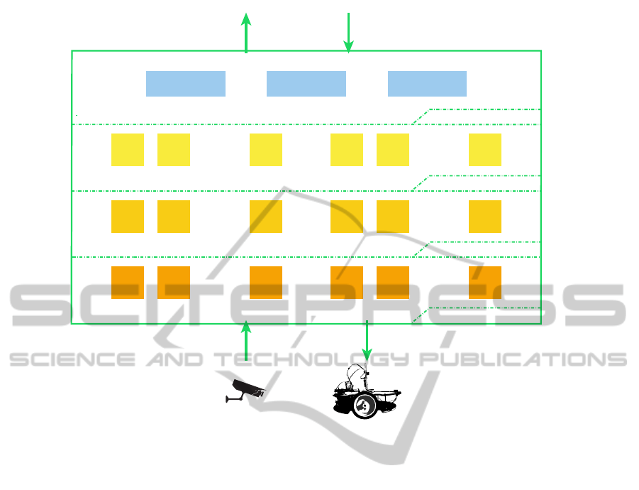
Subscription
Observation
Wish
Access Layer
Inference / Reification Layer
Stimuli
Actions
APPLICATIONS
Statuses
Commands
Translation Layer
SW
2
SW
1
SW
p
...
AW
2
AW
1
AW
q
...
ST
2
ST
1
ST
J
...
AT
2
AT
1
AT
k
...
SG
2
SG
1
SG
n
...
WR
2
WR
1
WR
m
...
Interface Layer
Figure 5: Concrete architecture.
• an end-user application, which performs domain
specific actions according to the state of the envi-
ronment model
3.1 DEA Framework
The DEA framework has been developed using Java
technologies. In particular, the request endpoints (i.e.,
the observation, subscription, and wish components)
have been integrated with Jess and web services, to
deal with the logic predicates and the communica-
tion with applications respectively. The communi-
cations between the domain-dependant components
have been implemented through SIS (Bernini et al.,
2012), a publish/subscribe framework based on the
multi-space metaphor.
3.2 DEA Platform
The end-user application provides users with an up-
dated information about people location inside a
building constituted by two rooms (sal1 and sal2) and
a passage connecting them. Moreover, the building is
populated by a mobile and controllable entity labeled
Poomba (i.e., a robot).
Thus, the environment model consists of the fol-
lowing entities: Light, MobileUnit, Person, and
Room. Each of them is characterized by the follow-
ing properties: Location, Type, and Id. More-
over, Light has also OnOffStatus that states if
the light is switched on or off, and Room has the
ContainedPeople property that maintains the num-
ber of people that are actually inside the room.
The above entities constitute the whole environ-
ment model since they entirely represent the “context
of interest”. Moreover, the model, by its own na-
ture, handles the entities in the same way and does not
specify any structural constraint between them. Possi-
ble physical/spatial considerations (e.g., the building
topology) have to be done on one or more external
physical space models.
The physical environment has been instrumented
with RFID sensors produced by Softwork in proxim-
ity of the entrance and the exit of each room, with a
BTicino system that controls the lights relying on the
OWN protocol, and with a mobile unit equipped with
actuators (to move the entity) and sensing devices (to
perceive stimuli for localization purpose).
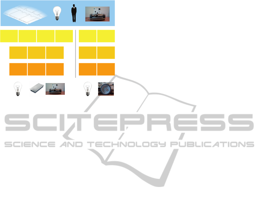
The implemented components dealing with
domain-related issues are sketched in Figure 6. At
a first look they may appear too many, but each
AnArchitecturefortheDesignofPlatformsSupportingResponsiveEnvironments
423
Room
ContPeople
SG
Lamp
OnOStatus
SG
Person
Location
SG
MobileUnit
Location
SG
OWNet
ST
Softwork
ST
Poomba
ST
MyHome
SW
RFIDSensors
SW
PoombaMov
SW
Lamp
OnOStatus
WR
MobileUnit
Location
WR
OWNet
AT
Poomba
AT
MyHome
AW
PoombaMov
AW
Figure 6: Domain-related components for the applicative
scenario.
one is actually very simple, reflecting a philosophy
of high-cohesion and low-coupling. In particular,
at the interfacing layer, MyHomeSW, RFIDSensorsSW,
and PoombaMovSW respectively interfaces with the
respective sensors to acquire the generated stim-
uli; MyHomeAW and PoombaMovAW respectively inter-
faces with the respective actuators to deliver actions.
At the translation layer, OWNetST, SoftworkST, and
PoombaST translate stimuli from the respective sen-
sors into abstract stimuli; OWNetAT and PoombaAT
translate abstract actions from the wish reasoners into
actions in a language that the target actuator is able
to understand. Finally, at the inference/reification
layer, RoomContPeopleSG, LampOnOffStatusSG,
PersonLocationSG, and MobileUnitLocationSG
are in charge of elaborating the abstract stimuli re-
spectively from the SoftworkST component to up-
date the ContainedPeople property of each Room
entity, from the OWNetST component to update the
OnOffStatus property of each Light entity, from
the SoftworkST component to update the Location
property of each Person entity, and from the
PoombaST component to update the Location prop-
erty of the MobileUnit entity; LampOnOffStatusWR
and MobileUnitLocationWR are in charge of reify-
ing the commands from the end-user application into
corresponding abstract actions and deliver them re-
spectively to OWNetAT and PoombaAT components.
3.3 End-user Application
The end-user application realizes the following be-
haviors in response to particular environment condi-
tions:
• If there is at least one person into the sal2 room,
all the lights must be switched on
• If there are no people into the sal2 room, all the
lights must be turned off
• If there is a professor in one of the two rooms, the
mobile unit must be located in the same place
The above behaviors will be realized as follows:
the lights will be switched when the first person en-
ters the sal2 room and switched off when the last one
exits; in the same way, when a professor enters one
of the two rooms, the mobile unit, if not in the same
place, will move to reach the room.
The end-user application is a simple Java program
that interfaces with the exposed web services of DEA
platform. Its basic behavior is to initially send sub-
scription requests and wait for status change notifica-
tions to trigger wish requests.
The following, for example, is the subscription re-
quest for observing changes in the number of people
that are present in the sal2 room:
Sen d e r :
Ca s e S tu d y A p p
Re c ip i en t :
Type = Room AND
Name = sal2
Su bs cr ip ti on Re qu es t :
Co n t a i n e d P e o p le
Thus, whenever a new person enters the sal2 room,
the application will receive a notification like the fol-
lowing:
Sen d e r :
Id = sal2
St a t u sC h a n g e :
Co n t a i n e d P e o p le 1 0 . 9
This message, for example, notifies that the sal2 room
now contains one person with a confidence equals to
0.9. Because there is at least one person in sal2, the
application logic triggers a rule that sends a wish re-
quest like the following:
Re c ip i en t :
Type = Li g h t AN D
Lo c a t i o n = s a l 2
Wi s h R eq u e s t :
On O f f St a t u s = On
This message requests that all the lights in the sal2
room have to be switched on.
It is interesting to notice that the previous notifica-
tion message could be received both if the sal2 room
already contains more than one person or no persons
yet. In the first case, the lights are already on and
the wish request does not produce any effect; in the
second, the lights are switched on. This could be a
representative example of delegation of logic.
Finally, to fulfill the last behavior, the application
performs the following subscription:
ICSOFT-EA2014-9thInternationalConferenceonSoftwareEngineeringandApplications
424

Sen d e r :
Ca s e S tu d y A p p
Re c ip i en t :
Type = P e r son A ND
Role = P r of e s s o r
Su bs cr ip ti on Re qu es t :
Lo c a t i o n
When Mr. White (who is a professor) will enter sal2,
the application will receive a message like the follow-
ing:
Sen d e r :
Id = m r _w h it e
St a t u sC h a n g e :
Lo c a t i o n = s a l 1 0 .9
The application then will send the following com-
mand:
Re c ip i en t :
Id = p o o mb a
Wi s h R eq u e s t :
Lo c a t i o n = s a l 1
3.4 Discussion
The design and implementation of the case study
application have highlighted the architectural advan-
tages of the solution presented in this paper. In par-
ticular, it has pointed out an extreme simplicity in the
development.
The necessary knowledge for interacting with the
architecture is reduced to sending and receiving well-
structured messages, containing data that only refers
to the defined entity model and known to the applica-
tions. This allows to totally abstract the purely tech-
nological and low-level interactions with the devices,
enabling the application to interface to an environ-
ment representation that is nearer to its logic.
The use of entity models and of an interaction
mechanisms linked to logic predications on them also
allow the simple adaptation of the application to dif-
ferent environment configuration. The logic the case
study application uses is completely unrelated from
the concrete environment configuration: for example,
the addition of new lights in the sal2 room or the in-
sertion of other professors into the domain entities set
does not lead to any modification to the application
logic, that remains equally compatible to the require-
ments. The a-priori assumed knowledge on the do-
main entities can be easily derived from targeted ob-
servation that only exploits the information provided
by the model (and possibly by the physical environ-
ment structure).
Reasoning on domain data has also made the im-
plementation of the logic less complex, reducing it to
an application of simplified rules.
The validation has not highlighted performance is-
sues, an aspect that will be further investigated conse-
quently to a prototype optimization.
4 RELATED WORKS
Devices interoperability is a well known issue
(Bonino et al., 2008)(Kusznir and Cook, 2010). De-
pending on the research field (more or less oriented to
hardware integration), the proposed solutions can be
classified in two main groups: the former composed
by integration platforms that merely unify communi-
cation mechanisms from and to devices; and the latter
composed by more complex architectures that offer an
environment representation to the applications, more
suited to the application domain.
DEA fits in the middle of these two classes, reduc-
ing their drawbacks and exploiting their advantages.
4.1 Integration Platforms
Solutions in this scope focus on the technological
problem of devices interoperability. Typically they
offer platforms that abstract specific communication
protocols and offer homogeneous mechanisms for in-
teracting with the devices. The general approach is to
define a set of communication requirements that ap-
plications have to use to interface with them. These
requirements are often represented by the use of com-
mon vocabularies to uniform syntax and semantics of
data and the adherence to a common communication
mode.
The CASAS Lightwight middleware (CLM)
(Kusznir and Cook, 2010), for example, is a solution
based on message-passing between information
sources (typically sensors) and consumers, that
uses the publish/subscribe paradigm: the interested
components subscribe to specific sources and conse-
quently receive the produced information, expressed
by a predefined XML syntax. Thomson et al. in
(Thomson et al., 2008) follows a service-oriented ap-
proach instead, proposing a framework that abstracts
devices and exposes them as web services or through
technologies like Java RMI.
Solutions of this kind often are foundations of re-
search projects, in particular in the field of Ambient
Intelligence and Ubiquitous Computing. CLM, for ex-
ample, is used as a base for the communication sys-
tem of the smart home CASAS (that, in the authors
knowledge, has not public results yet); the framework
by Thomson et al. constitutes instead the device ab-
straction infrastructure of Amigo (Janse et al., 2008),
AnArchitecturefortheDesignofPlatformsSupportingResponsiveEnvironments
425

that proposes a service-oriented architecture for smart
homes.
These integration platforms only deal with devices
and their data, delegating the end-user applications
to fit them into an appropriate environment represen-
tation. This allows these solutions to be potentially
used in any application domain that concerns hard-
ware components. However, defining and maintain-
ing a proper environment model often is a non-trivial
task.
DEA follows the general approach above de-
scribed and takes inspiration from the CLM publish/-
subscribe model for its data abstraction layers, by al-
lowing the communication between device compo-
nents and inference/reification ones through the SIS
framework. The syntax and semantic of the data are
defined in a shared vocabulary, that models device
raw data in a plain format. In addition, DEA allows to
define and maintain an environment model, that could
include the architecture into the “domain-oriented ar-
chitectures” group.
4.2 Domain-oriented Architectures
Domain-oriented architectures mainly focus on offer-
ing information models that fit particular application
domains. These architectures usually include device
interoperability mechanisms, that they use to infer do-
main knowledge from heterogeneous sources.
Usually information models refer to abstract rep-
resentation of an environment, whose complexity de-
pends on the specific domain of the solution. In gen-
eral, solutions in this scope add an abstraction layer
to the previous group, with the goal of infer domain
knowledge from device data.
In the field of home automation we found, for
example, DOG Gateway (Bonino et al., 2008), an
architecture for “intelligent domotic environments”,
that abstracts hardware components into an ontolog-
ical representation of the overall environment, which
comprises appliances, various systems (e.g., HVAC,
gas, lightning) and simple devices (e.g., lamps), and
their spatial location into the environment topology.
In this case, the gap between device data and domain
knowledge is relatively small: most of the entities at
domain level are devices or their aggregations.
In the field of Ambient Intelligence, and in more
complex automation solutions, the richness of the
models may increase, including more than just device
entities and their statuses. In these scenarios, models
are enriched by more abstract entities, like people or
weather conditions; in general, using an Ubiquitous
Computing term, these models deal with context in-
formations.
Fernandez-Montes et al. in (Fernandez-Montes
et al., 2009) propose a Smart Environments software
reference architecture. This architecture implements
a perception-reasoning-action cyclic flow. Through
a component called Ontologiser, it organizes data,
standardizing them into an environment model. This
model includes devices information (i.e., their spatial
location and status), inhabitants (like personal data,
localization, and health status) and other environment
information (e.g., room temperature and brightness).
This “perceived” information is used to reason about
the environment and then to possibly act on it.
In Ubiquitous Computing, the focus moves further
on even more abstract environment representation,
where devices may be mere information sources (e.g.,
RFID tags detecting people presence), thus some-
times directly excluded from the model. An example
is Gaia (Rom
´
an et al., 2002), defined by its authors
as a middleware for Active Spaces. An Active Space
is an instrumented environment coordinated by a soft-
ware infrastructure that extracts context information,
that can be useful to adapt the environment itself to
the user’s needs.
The main common drawback of the solutions of
this class is that each of them supports a specific do-
main and consequently defines a static information
model, concretely excluding its reusability in differ-
ent domains. DEA overcomes this issue by defining
a plain and simple method for modeling domain in-
formation that is based on property-value pairs. Thus,
we define how to model information, but not what,
leaving to domain experts or anyone who wants to use
the architecture the definition of its own environment
model and how device data are linked to it.
Another aspect regards the action process, that is,
how applications act on the environment to change its
state. Although each of the presented architectures
model in a clear way the perception of the environ-
ment (the transformation of device-related data into
domain knowledge), there are not details for its sym-
metric process. The best expectation should be to ex-
press actions using the same syntax and semantic of
the domain model. DEA complies this expectation by
allowing the applications to express wishes on entity
statuses, that will be transformed into feasible actions
for the appropriate hardware components.
5 CONCLUSIONS AND FUTURE
DIRECTIONS
The paper presented an architecture that allows the
integration of heterogeneous devices in order to offer
end-user applications a representation of the environ-
ICSOFT-EA2014-9thInternationalConferenceonSoftwareEngineeringandApplications
426

ment at the right level of abstraction. Thus, applica-
tions can observe and control the physical environ-
ment reasoning only on domain information.
The proposed architecture is independent from the
application domain, highly modular and open. In fact
it is not designed for a specific scenario, but defines
precise levels of abstraction in which placing well-
defined components that are domain dependant. Such
components are characterized by a high independence
and have well-defined interfaces, which specify the
structure of the data to be treated and how to com-
municate with the rest of the architecture. This en-
forces the openness of the solution, since it encour-
ages the addition of components that adhere to the in-
terfaces and that realize the needed abstraction flows,
thus making easy to incrementally support new de-
vices and entity models.
The implementation of a case study has also
demonstrated the actual simplification in terms of ac-
cess to the environment by end-user applications. In
particular, the case study has emphasized how the ar-
chitectural solution allows to clearly separate the im-
plementation strategies (that are responsibility of the
applications) from how they perceive and modify the
environment (aspects completely managed by the ar-
chitecture).
Future developments will include the identifica-
tion of a solution to the problem of the aging of the
statuses of the entities. This problem, identified in
the analysis stage, regards the updating of the con-
fidence level of the property to which this attribute
lapses in the absence of sensory stimuli. Related to
this issue, we plan to include the management of his-
tories of the changes. This implies to consider tem-
poral aspects of the information that will be managed
using TAM (Time Aware Machine) (Fiamberti et al.,
2012), a framework that provides the support in con-
textualizing information in a temporal context.
REFERENCES
Aiello, M. and Dustdar, S. (2008). Are our homes ready
for services? A domotic infrastructure based on the
web service stack. Pervasive and Mobile Computing,
4(4):506–525.
Bernini, D., Fiamberti, F., Micucci, D., and Tisato,
F. (2012). Architectural abstractions for spaces-
based communication in smart environments. Jour-
nal of Ambient Intelligence and Smart Environments,
4(3):253–277.
Bonino, D., Castellina, E., and Corno, F. (2008). The DOG
gateway: enabling ontology-based intelligent domotic
environments. Consumer Electronics, IEEE Transac-
tions on, 54(4):1656 –1664.
Bullivant, L. (2006). Responsive Environments: Architec-
ture, Art and Design (V&A Contemporaries). Victoria
& Albert Museum.
Butz, A. and Kr
¨
uger, A. (2003). A generalized peep-
hole metaphor for augmented reality and instrumented
environments. In Proceedings of The International
Workshop on Software Technology for Augmented Re-
ality Systems (STARS).
Cook, D. J. and Das, S. K. (2007). How smart are our en-
vironments? an updated look at the state of the art.
Pervasive and Mobile Computing, 3(2):53–73.
Fernandez-Montes, A., Ortega, J., Alvarez, J., and
Gonzalez-Abril, L. (2009). Smart environment soft-
ware reference architecture. In Fifth International
Joint Conference on INC, IMS and IDC, 2009. NCM
’09, pages 397–403. IEEE.
Fiamberti, F., Micucci, D., and Tisato, F. (2012). An object-
oriented application framework for the development
of real-time systems. Lecture Notes in Computer Sci-
ence, 7304 LNCS:75–90.
Janse, M., Vink, P., and Georgantas, N. (2008). Amigo
architecture: Service oriented architecture for intelli-
gent future in-home networks. In Constructing Am-
bient Intelligence, volume 11 of Communications in
Computer and Information Science, pages 371–378.
Springer Berlin Heidelberg.
Kim, J. E., Boulos, G., Yackovich, J., Barth, T., Beckel, C.,
and Mosse, D. (2012). Seamless integration of hetero-
geneous devices and access control in smart homes. In
2012 8th International Conference on Intelligent En-
vironments (IE), pages 206–213.
Kusznir, J. and Cook, D. (2010). Designing lightweight
software architectures for smart environments. In
2010 Sixth International Conference on Intelligent
Environments (IE), pages 220 –224. IEEE.
Negroponte, N. (1975). Soft architecture machines. MIT
Press.
Ristau, H. (2008). Publish/process/subscribe: Message
based communication for smart environments. In
2008 IET 4th International Conference on Intelligent
Environments, pages 1–7.
Rom
´
an, M., Hess, C., Cerqueira, R., Ranganathan, A.,
Campbell, R., and Nahrstedt, K. (2002). A middle-
ware infrastructure for active spaces. Pervasive Com-
puting, IEEE, 1(4):74 –83.
Stevens, W., Myers, G., and Constantine, L. (1979). Clas-
sics in software engineering. chapter Structured De-
sign, pages 205–232. Yourdon Press, Upper Saddle
River, NJ, USA.
Thomson, G., Sacchetti, D., Bromberg, Y., Parra, J., Geor-
gantas, N., and Issarny, V. (2008). Amigo interop-
erability framework: Dynamically integrating hetero-
geneous devices and services. In Constructing Am-
bient Intelligence, volume 11 of Communications in
Computer and Information Science, pages 421–425.
Springer Berlin Heidelberg.
AnArchitecturefortheDesignofPlatformsSupportingResponsiveEnvironments
427
