
Initial Alignment Scheme and Tracking Control Technique
of Free Space Optics Laser Beam
Takeshi Tsujimura, Shigeki Muta, Yuichiro Masaki, and Kiyotaka Izumi
Department of Mechanical Engineering,
Graduate School of Science and Engineering, Saga University, Saga, Japan
Keywords: Free Space Optics, Communication, Laser, Robot, Control, Alignment, Tracking, Gaussian Beam.
Abstract: This paper describes the laser beam alignment techniques for free space optical communication. Bilateral
laser transmission system is designed between two active free-space-optical apparatuses, which are
equipped with galvanic scanners, E/O and O/E converters and are able to control laser beam discharging
directions. Two alignment strategies are proposed with regard to the transient and steady state of optical
signal transmission. Search method for initial alignment is established based on the Gaussian beam optics,
and a tracking control system is constructed for laser beam to maintain stable telecommunication between
roaming transmission equipments. Experiments reveal that the proposed techniques enable the free space
optics system to locate the target receiver and to pursue the unstable transmission apparatus.
1 INTRODUCTION
Free space optics (FSO) is an alternative to the main
telecommunication technology such as optical fiber
network or wireless local area network. It realizes
telecommunication by transmitting collimated laser
beam in the air (Willebrand, 1999) (Ghimire, 2011)
(Yamashita, 2011). FSO system is superior to
optical fiber system in installation time and cost. It
provides securer broadband communication than
wireless LAN against phone tapping because laser
beam does not spread like radio wave. On the other
hand, conventional FSO is considered not to be
ubiquitous but stationary telecommunication
technology as it is designed for fixed point-to-point
communication.
We have proposed active FSO technology
(Tsujimura, 2004) to realize ubiquitous broadband
communication in the user network where the
transmission length is around 100 meters. It can be
improved to an optical mesh network that serves as a
rural area network as shown in Fig. 1. This figure
illustrates a prospect of a free space optics network
among islands, where the stationary FSO
apparatuses relay transmission laser beam.
Each apparatus contains a transmitter and a
receiver. Laser beams transmit bi-directionally
between two pieces of apparatus. It is necessary to
achieve long-distance transmission with thin laser
beam from the transmitter to the receiver in the air.
The positional relationship between the apparatuses
is not always stationary but may shift by inches.
Figure 1: Optical network based on free space optics.
One of remarkable features of active FSO system
is the mobile terminal tracking technique (Tsujimura,
2004). We are planning to apply this system to the
hundreds-of-meter-long transmission. Laser beam
alignment is essential to complete communication
between remotely separated transmission
apparatuses, and communication quality depends on
the alignment accuracy (Yoshida, 2004).
Active free space
optics apparatus
83
Tsujimura T., Muta S., Masaki Y. and Izumi K..
Initial Alignment Scheme and Tracking Control Technique of Free Space Optics Laser Beam.
DOI: 10.5220/0005101200830088
In Proceedings of the 5th International Conference on Optical Communication Systems (OPTICS-2014), pages 83-88
ISBN: 978-989-758-044-4
Copyright
c
2014 SCITEPRESS (Science and Technology Publications, Lda.)
We are studying on laser beam alignment
method. Bilateral free space optics apparatus is
designed and a prototype of the distributed control
system is constructed using a galvanic scanner to
steer the laser beam direction. Two types of laser
beam alignment strategies are proposed according to
the transmission condition and the alignment
procedure is established. Experiments confirm the
validity of the proposed searching algorithm for
optical signal connection and the tracking control
system in the active free space optics
communication.
2 ACTIVE FREE SPACE OPTICS
SYSTEM
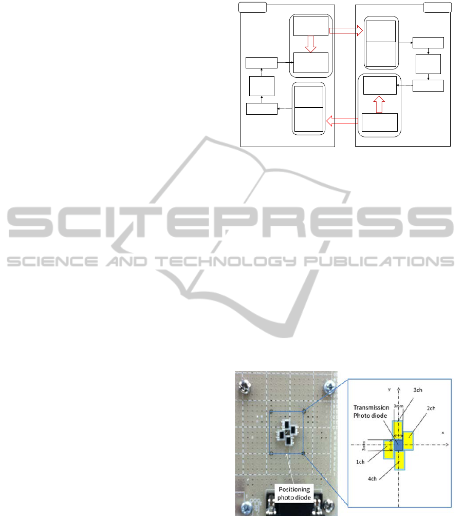
Figure 2 indicates the block diagram of the active
FSO system, where two FSO setups discharge laser
beam each other to realize bilateral optical
communication. Each is equipped with a PC to
control both a receiver and a transmitter. The
galvanic scanner guides the laser beam direction
based on the arrival point of the laser beam on the
opposite receiver.
The proposed active FSO system tracks a mobile
terminal maintaining broadband communication
using the laser positioning scheme. Positioning
error of laser beam is detected by the dedicated
sensor device and is transferred to the feedback
controller carried upon the upstream transmission
line directing from the opposite transmitter. The
feedback control signals are superposed on the
optical signals transmitting communication data.
The transmitter is composed of an E/O converter
and a galvanic scanner. The E/O converter contains
an AlGaIn laser diode whose frequency bandwidth is
up to 1.2 GHz. We use 658 nm-wavelength laser
diode in this paper. The E/O converter discharges a
transmission laser pulses to realize broadband
communication. The laser beam is focused several
millimetres in diameter.
The galvanic scanner is equipped with two
motor-driven reflection mirrors. It reflects laser
beam and discharges it spherically in the air. Those
mirrors are attached to the orthogonal axes of
motors. They are controlled by servo motor drivers
with a resolution of 4.77×10
-4
deg, which
corresponds to an accuracy of 4.16×10
-2
mm on the
receiver plane.
Thus we can direct the laser beam, discharged
from the laser diode, to the objective direction by
controlling the motors of the galvanic scanner.
Figure 2: Distributed control system of bilateral FSO.
The receiver involves both the transmission
photodiode and the positioning ones. An O/E
converter for fiber optics use serves as the
transmission photodiode by modifying to FSO
transmission by adjusting its optical system. A
SiPIN photodiode is built in the O/E converter. Its
maximum frequency bandwidth and wavelength
range are 1 GHz and 400 to 1000 nm, respectively.
The positioning photodiodes are designed and
manufactured as shown in Fig. 3, where four
positioning photodiodes are surrounding the
transmission photodiode (Muta, 2013). They are
SiPIN photodiodes, whose wavelength range and
cutoff frequency are from 320 to 1100 nm, and 25
MHz, respectively.
Figure 3: Positioning photodiode.
They are used only for detection of laser
luminescence. The positioning photodiode unit
outputs four values of voltages representing laser
intensities of the corresponding positions of each
photodiode.
Photo
diode
AD board
PC
O/E
converter
Receiver
Transmitter
E/O
converter
Laser beam
Galvanic
scanner
DA board
Laser
beam
PC
DA board
Galvanic
scanner
E/O
converter
Laser beam
Laser
beam
Transmitter
Photo
diode
O/E
converter
Receiver
AD board
FSO#2
FSO#1
OPTICS2014-InternationalConferenceonOpticalCommunicationSystems
84

3 LASER BEAM CONTROL
TECHNIQUES
Free space optics communication is performed
between two pieces of FSO apparatus. Single
channel of the bilateral transmission lines is
illustrated in Fig. 4, which describes only a
transmitter and a receiver of its neighbouring
apparatus tens of meters away. A thin laser beam is
introduced from a transmitter to an opposite receiver
to realize broadband communication.
The system keeps the laser spot within the
sensible range of the receiver by controlling the
discharge direction of the laser beam with a galvanic
scanner. The scanner is equipped with two pairs of
servo motor driven mirrors to reflect laser beam to a
designating direction. The objective mirror angles
are calculated based on the laser intensity measured
by the positioning photodiode.
The receiver contains two types of detectors: the
transmission photodiode and positioning
photodiodes. The arrived laser beam is introduced to
the transmission photodiode to catch the optical
transmission signals. The function of the latter
photodiodes is evaluation of positioning error of the
laser beam. Their output data is transferred to the
galvanic scanner to generate feedback control
command.
The thin laser beam is required to keep hitting
the small receiver to maintain communication even
if the target drifts.
We have prepared two modes of laser beam
alignment: the transient and the steady state. In the
former state, communication is not established yet,
as the optical signals do not successfully reach the
receiver. It is necessary to find out presice travelling
route of the laser beam from the transmitter to the
receiver.
Figure 4: Active free space optics system.
In the steady state, the laser beam arrives within
the detection range of the positioning photodiodes.
Based on the measured optical intensity, the tracking
control is applied to adjust the laser hitting point
onto the midst of the positioning photodiodes where
the transmission photodiode is installed.
Each of two control schemes is applied
according to the state as shown in Fig. 5.
It starts with the transient state in general as the
laser beam is wide of the receiver. Thus, the system
scans the laser beam around over the area where the
target receiver is possibly located, searching for the
line-of-sight from the transmitter to the receiver.
After monitoring the intensity of the received laser
luminescence, the optimum physical relationship
between the transmitter and the receiver is
determined by adjusting the laser beam direction so
that received signal intensity would be the highest.
Once the receiver detects the laser luminescence,
a feedback control algorithm steers the laser beam
direction so that the laser spot keeps within the
sensible area on the receiver. In the steady state, the
laser beam can track the receiver automatically. The
target motion is estimated based on the output of
positioning photodiodes that catch the laser
luminescence discharged from the opposite
transmitter.
Figure 5: Laser beam alignment procedure.
If the laser beam misses reaching the target
receiver by accident and the transmission is
disconnected, the system is incapable of estimation
and loses track of the target. Then the mode is turns
to the transient state, and starts searching again.
3.1 Initial Alignment Scheme to
Capture Optical Signals
The proposed system searches for the line-of-sight
of the laser beam in the transient state. When the
distribution of the laser beam intensity is previously
Start
Search for
communication
Tracking
control
Disconnect?
no
yes
InitialAlignmentSchemeandTrackingControlTechniqueofFreeSpaceOpticsLaserBeam
85
known, it helps the search easier than observing all
over the space. If the laser beam corresponds to
Gaussian beam optics, it is possible to analytically
estimate the peak of the distribution. That means we
can adjust the optical axis of the laser beam just onto
the receiver.
Let us consider the formulation of the laser beam
in the x-y-z coordinate system, assuming the optical
axis is parallel to the z-axis. When a laser beam hits
at (a, b) on the x-y plane, the optical intensity, E
xy
of
a Gaussian beam at (x, y) on the x-y plane is
theoretically formulated as
=
exp
()
+ ()
(1)
where E
0
is the maximum intensity, which is
observed on the optical axis (a, b).
By locating the positioning photodiode at (x
0
,
y
0
), we obtain the laser luminescence intensity, E
x0y0
at that point. Then equation (1) gives the following
equation.
(
)
+ (
)
=
log
(2)
Because this equation contains four unknown
parameters, four independent conditions are
necessary to solve the simultaneous equation in
general. If we prepare four positioning photodiode
at (x
0
, y
0
), (x
0
, y
1
), (x
1
, y
0
), (x
1
, y
1
), position (a, b) of
the intensest laser spot is determined, by solving
four simultaneous equations in terms of four
variables, as
a =
(
+
)
+
+
2
{
+
+
}
(3)
b =
+
(
+
)
+
2
{
+
+
}
(4)
where
,
,
represent
log
, log
, log
,
and E
x0y1
,
E
x1y0
, E
x1y1
are the laser luminescence
intensity measured at (x
0
, y
1
), (x
1
, y
0
), (x
1
, y
1
),
respectively.
We have carried out a fundamental experiment to
confirm the analysis. The planar distribution of the
laser beam intensity is actually measured by the
positioning photodiode. It can be approximated by a
Gaussian distribution at E
0
= 8.0 and w = 5.0.
The position (a, b) of the laser beam optical axis
is evaluated by applying the measured values of the
photodiodes to the equations (3) and (4) with regard
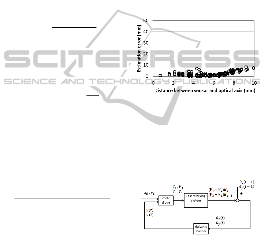
to various sensor placement. Figure 6 shows the
estimation results on condition the photodiodes are
arranged at four corners of 10 mm square. The
vertical axis represents the estimation error of the
optical axis position, while the horizontal axis
denotes the distance between the photodiodes and
the optical axis. It proves that the proposed method
estimates the optical axis position of the laser beam
within an accuracy of 10 mm.
Figure 6: Estimation results of optical axis.
3.2 Tracking Control Technique for
Laser Beam
The tracking control is conducted in the steady state
to steer the laser beam to the midst of four
photodiodes. A feedback control system is
established between the transmitter and the receiver.
A block diagram of proportional control system is
shown in Fig. 7.
Figure 7: Block diagram of laser tracking system.
Equations (5) and (6) express the proportional
control formulations in terms of the command mirror
angles for two-degree-of-freedom laser beam angles,
where θx(t) and θy(t) represent the mirror angles,
Kx, Ky do the feedback gains, V
1
, V
2
, V
3
and V
4
do
the output voltages of the positioning photo diode,
and θx(t-1), θy(t-1) do the previous angles.
OPTICS2014-InternationalConferenceonOpticalCommunicationSystems
86
(
)
=
(
)
+
(
1
)
(5)
(
)
=
(
)
+
(
1
)
(6)
This system controls the laser beam to make
these four outputs equal. Each positioning
photodiode covers a part of the laser spot, and
generates voltage of the corresponding share of the
laser intensity. When the laser beam shifts aside, the
output voltages of four photodiodes increase or
decrease with regard to the shift direction. The
feedback controller directs the laser beam to
compensate the gap based on the balance of the
photodiode outputs. Thus, the proposed tracking
system is able to chase the target belatedly.
Some experiments are conducted to the active
FSO system to track moving photodiodes. A
motorized stage carries the target positioning
photodiodes along a designated trajectory and the
control responses are measured and evaluated.
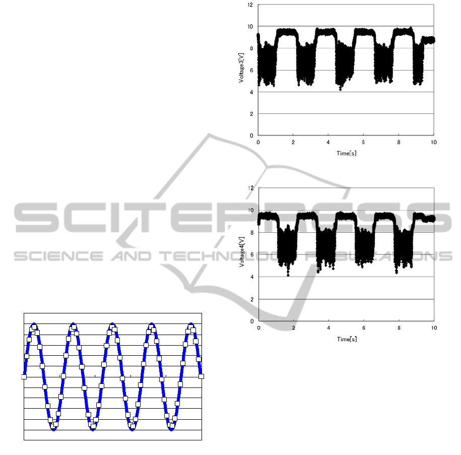
The positioning photodiodes are guided to trace a
vertically reciprocating trajectory, shown by a solid
line in Fig. 8, on the condition that the target speed
is 90 mm/s, the distance from the galvanic scanner
to the positioning photodiode is 5 m, and its motion
amplitude is 50 mm.
Figure 8: Trajectory of target and laser beam.
Channels 1 and 2 catch the horizontal motion.
Channels 3 and 4 observe the vertical motion.
Figure 9 (a) and (b) indicate the amplified output
voltages of the positioning photodiodes, channels 3
and 4. They vary as much as 7.5± 2.5 V. Their
oscillation phases shift each other by π/2 according
to up and down motion of the target. Results suggest
that the laser beam is chasing after the photodiodes
synchronously. Output of channel 1 and 2 is almost
unchanged, because the laser beam swings vertically.
Figure 9 (a): Output voltage of photodiode, ch. 3.
Figure 9 (b): Output voltage of photodiode, ch. 4.
The reflection mirrors equipped in the galvanic
scanner are controlled by servo motors according to
the proportional control algorithm. Their command
angles are determined based on the positioning
photodiode output values. Figure 10 (a) and (b)
show the rotation angles of the horizontal and
vertical mirrors, respectively. The vertical mirror
rotates as much as 0.65
deg in amplitude, while the
horizontal mirror holds still.
Actual motion of the laser beam is compared
with the target photodiode trajectory in Fig. 8, where
white squares indicate the measured trace of the
laser spot. It reveals that the proposed control system
is successful in tracking a mobile target with the
laser beam scanning system from far away.
-60
-50
-40
-30
-20
-10
0
10
20
30
40
50
60
0
2 4 6 8
10
Time [s]
Vertical position [mm]
InitialAlignmentSchemeandTrackingControlTechniqueofFreeSpaceOpticsLaserBeam
87
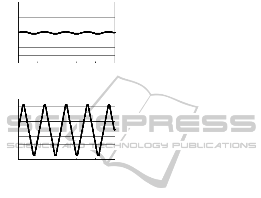
Figure 10 (a): Motion of horizontal mirror.
Figure 10 (b): Motion of vertical mirror.
4 CONCLUSIONS
Bilateral telecommunication system of the active
free space optics system is proposed which is
equipped with distributed control system of the laser
beam scanners to apply to longer-distance optical
transmission in the air. Dedicated apparatus is
designed and prototyped both for communication
and laser beam control. The feedback control system
is also designed to adjust the laser beam travelling
from the distant transmitter within the receiver by
steering the laser beam direction based on the
positioning photodiodes.
Two states are assumed with respect to optical
signal transfer, and the alignment strategy is
proposed according to the state. Searching method
is investigated for the transient state, and its
algorithm is established to determine the summit of
the laser luminescent by analysing the Gaussian
beam optics. It enables the galvanic scanner to
efficiently hunt for the target receiver.
Tracking control is adopted for the scanning
system to maintain optical communication in the
steady state. It directs the laser beam to follow the
target motion and to remain on the receiver.
Experiments clarify that the proposed system
successfully steer the laser beam to follow the target
receiver. It enables the transmitter to maintain long-
distance transmission in high quality even when the
receiver fluctuates.
ACKNOWLEDGEMENTS
This work was partially supported by Strategic
Information and Communications R&D Promotion
Program (SCOPE) of Ministry of Internal Affairs
and Communications, Japan.
REFERENCES
Ghimire, R., Mohan, S., 2011. Auto tracking system for
free space optical communications. 13th International
Conference on Transparent Optical Networks, pp.1-3.
Muta, S., Tsujimura, T., Izumi, K., 2013. Laser beam
tracking system for active free-space optical
communication. Proc. SII2013, pp.879-884.
Tsujimura, T., Yoshida, K., 2004 Active free space optics
systems for ubiquitous user networks. Proc. 2004
Conference on Optoelectronic and Microelectronic
Materials and Devices.
Yamashita, T., et al., 2011. The new tracking control
system for Free-Space Optical Communications. 2011
International Conference on Space Optical Systems
and Applications, pp.122-131.
Yoshida, K., Yano, T., Tsujimura, T., 2004. Automatic
optical axis alignment for active free space optics.
Proc. SICE Annual Conference 2004, pp. 2035-2040.
Willebrand, H., Ghuman, B. S., 1999. Free-Space Optics:
Sams Publishing.
-0.8
-0.6
-0.4
-0.2
0
0.2
0.4
0.6
0.8
0 2
4 6
8
10
Time [s]
Angle [degree]
-0.8
-0.6
-0.4
-0.2
0
0.2
0.4
0.6
0.8
0 2 4 6 8 10
Time [s]
Angle [degree]
OPTICS2014-InternationalConferenceonOpticalCommunicationSystems
88
