
Scenario Generation Based on Existing Software Operation History
Junko Shirogane
Tokyo Woman’s Christian University, Tokyo, Japan
Keywords:
User Interface, Scenario, Usability.
Abstract:
Scenarios, which represent operation flows of a software package, are often described in requirements elic-
itation phase by a natural language. Stakeholders that do not have knowledge of software development are
said that they can easily understand and describe scenarios. However, defining appropriate granularities of
input and output items and individual operations and describing scenarios without mistakes and missing are
difficult. Actual task flows are not always appropriate for computer operation flows. In addition, even if the
actual task flows in business are strictly represented in scenarios, software may not be usable. it is difficult to
describe appropriate operation flows considering usability in scenarios. When a new software package is de-
veloped, stakeholders may survey existing software packages similar to the software package that they require.
In this method, to support for describing appropriate scenarios, stakeholders try to use the existing software
packages, and scenarios are generated using the operation histories. Scenarios are customized considering the
actual task flows in business, limitations of input and output orders, and usability, and stakeholders can obtain
the required scenarios.
1 INTRODUCTION
In requirements elicitation phase, operation flows of
GUIs (Graphical User Interfaces) are often defined as
scenarios. Scenarios represent interactions between
users and software. Because scenarios often are writ-
ten in a natural language, stakeholders that do not
have knowledge on software development are said
that they can easily understand and describe.
Appropriate operation flows are difficultly de-
fined. Task flows in business, limitations of input
and output orders, and usability should be considered.
Usability issues include operation flows (Shirogane
et al., 2014). Stakeholders can define the actual task
flows and limitations of input and output orders in
scenarios. However, even if the actual task flows are
strictly realized as software, the flows may not be ap-
propriate for operation flows, and also the software
do not always become usable. It is necessary to de-
fine task flows as appropriate operation flows in com-
puters and to consider appropriate operation flows for
devices, such as computers, smart phones, and tablet
computers.
When stakeholders describe scenarios, there are
some difficulties other than defining appropriate op-
eration flows. One is defining appropriate granular-
ities of input and output items and individual opera-
tions. The other is defining operation flows without
mistakes and missing. Resolving these problems, it is
preferable to support stakeholders to describe scenar-
ios.
Currently, various software packages are devel-
oped and provided. When stakeholders make plans
to use a new software package, there may be cases
that the similar software packages have been already
developed. In requirements elicitation, existing soft-
ware packages are often surveyed. Thus, stakeholders
may survey the similar software packages and clarify
their requirements.
This method supports to describe scenarios by
stakeholders. Stakeholders try to use the existing
software packages similar to their required software,
and scenarios are generated from the operation his-
tories. Stakeholders confirm the generated scenarios
and customize considering their business and usabil-
ity.
The scope of this paper is to describe scenario
generation. For scenario customization, stakeholders
can consider in terms of their business, because they
are familiar to their business, and scenarios are writ-
ten in a natural language. The research of scenario
customization in terms of usability is now ongoing.
407
Shirogane J..
Scenario Generation Based on Existing Software Operation History.
DOI: 10.5220/0005106804070412
In Proceedings of the 9th International Conference on Software Engineering and Applications (ICSOFT-EA-2014), pages 407-412
ISBN: 978-989-758-036-9
Copyright
c
2014 SCITEPRESS (Science and Technology Publications, Lda.)
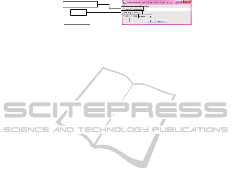
4. A clerk inputs the video's ID for ren!ng
5. The system shows the Rent day
6. A clerk selects the term of ren!ng
Figure 1: Example of correspondences between input/output items and events.
2 RELATED WORKS
Although researches to generate scenarios described
in a natural language are few, there are researches to
generate scenarios described some formal languages.
For example, Repond et al. proposed definitions
of metamodels for use case diagrams and scenarios
(Repond et al., 2011). Use case diagrams and scenar-
ios are described along with the metamodels, and used
for reverse engineering. Existing system is executed
based on the use case diagrams and the execution
trace is recorded. The execution trace is mapped to
the scenarios. Thus, the execution trace corresponds
to the event flow.
Amoyt et al. proposed a tool “UCMEXPORTER”
to transform Use Case Maps (UCMs) (Buhr, 1998)
to scenarios (Amyot et al., 2010). Scenarios of their
method is represented by Message Sequence Charts
(MSCs). According to their study, UCMs can be used
for various requirements analysis. MSCs are suited
for detailed design. Due to UCMEXPORTER, gaps
between models in requirements analysis phase and
design phase.
However, scenarios of these methods are not de-
scribed in a natural language. Additionally, to use
these methods, models must be described. Thus, it is
difficult for stakeholders that do not have knowledge
on software development.
3 FEATURE
Facilitate to Describe Scenarios by
Stakeholders
Although stakeholders that do not have knowledge of
software development are said that they can easily de-
scribe scenarios, it is difficult to describe scenarios in
appropriate granularities and without any missing in-
put and output items. Because operation histories of
existing software packages are used to generate sce-
narios, this method can support to unify the granulal-
ities and reduce the missing input and output items.
Support to Define Appropriate Scenarios
It is difficult to define appropriate operation flows as
scenarios. Because usable operation flows is espe-
cially difficulty to define, there are many cases that
usability issues become clear in using prototypes or
the actual software. Defining input and output items
and individual operations as appropriate granularities
without mistakes and missing are also difficult.
This method assumes that stakeholders try to use
existing software packages like prototypes. Thus,
stakeholders recognize usability issues for operation
flows, and can describe scenarios resolving the us-
ability issues. In addition, because existing software
packages are used to generate scenarios, granularities
of input and output items and individual operations
are considered to be appropriate, and mistakes and
missing are few.
4 CORRESPONDENCES
BETWEEN GUIS AND
SCENARIOS
Each task in a scenario is called an “event”, an oper-
ation flow is called an “event flow”. In requirements
elicitation phase, scenarios are used to represent in-
teractions between users and software in use cases of
UML (Unified Modeling Language). Use cases repre-
sent functions of software. Thus, scenarios represent
usage patterns of use cases. In this method, an event
is described a sentence.
Each event represents input from end users, out-
put to end users, and system processes by a natural
language. Focusing on events of input/output from/to
end users, input and output items appear as objects in
sentences of a scenario. Because GUIs are realized
based on scenarios, these input and output items are
realized as widgets in a window. Figure 1 shows the
correspondences. The evens from 4 to 6 in this fig-
ure represent a flow of a function “renting videos” in
the rental video management system, and the window
realize the event flow.
ICSOFT-EA2014-9thInternationalConferenceonSoftwareEngineeringandApplications
408

(1)
(2)
(3)
(5)
(4)
(6)
Figure 2: Example of window switching.
5 SUPPORT TO SCENARIO
DESCRIPTION
In this method, stakeholders try to use an existing
software package, then, scenarios are generated using
the operation histories. By modifying the generated
scenarios, scenarios that stakeholders require can be
obtained. Items in operation histories are follows:
• Window activation
• Window contents
– Widget types
– Label names of widgets (only widgets on which
label names are put)
– Coordinates of widgets
– Widget size
• Widgets operated by end users
• Window deactivation
The generation is performed by following four
steps.
1. Extraction of window switching
2. Analysis of associations between widgets and
their label names
3. Analysis of operations in a window
4. Generation of scenarios
5.1 Extraction of Window Switching
In operation histories, various flows of function us-
ages are recorded. Thus, it is necessary to divide the
flows in operation histories into each function usage.
Functions of desktop software start to be used
from a certain window, and windows for input and
output are displayed. When functions finish to be
used, the windows for input and output are closed,
and only the certain window is displayed. Web appli-
cations are similar to desktop software. Functions of
web applications start from the top page, and the top
page is shown again in finishing the functions. Here-
after, the certain window and the top page are called
“main window”.
Thus, a flow of function usage is identified as fol-
lows.
Start: Operation to widgets in the main window.
End: After window switching from the start, only
the main window is displayed, again.
The main window is identified as the window dis-
played first in starting the software by analyzing the
first activated window in operation histories. The
“End” point of a flow is also identified by analyzing
window activation and window deactivation. When
a function is used plural times, certain flows are
recorded plural times in the operation histories. In
this case, the same flows are integrated.
Figure 2 shows an example of window switching
of a function “renting video”. The numbers (1)-(6)
indicate windows, and the window (1) is the main
window. Arrows indicate the direction of the window
switching.
5.2 Analysis of Associations Widgets
and their Label Names
5.2.1 Instruction Labels and Target Widgets
Input and output items are described in events as ob-
jects described in 4. These items are realized as wid-
ScenarioGenerationBasedonExistingSoftwareOperationHistory
409

gets in GUIs. Widgets have label names that repre-
sent the names of input and output items. That is, la-
bel names indicate instruction of input from end users
and output to end users.
For some types of widgets, such as button and
menu item widgets, label names are put on them.
However, there are types of widgets on which label
names are not put, such as text field, list box, and
combo box widgets. For these widgets, label wid-
gets are associated with these widgets, and the label
names of the label widgets are used as the label names
of these widgets.
In addition, although for other types of widgets,
such as radio button and check box widgets, label
names are put on, the label names indicate selections,
not instructions. For example, for an event “A clerk
selects customer type” in a scenario, the input item is
“customer type”. When this item is realized as radio
buttons, the label names of the ratio button widgets
are not “customer type”, but selections, such as “reg-
ular” and “senior”. In this case, a label widget is asso-
ciated with these radio button widgets, and the label
name of this label widget is used as the label name of
the ratio button widgets.
In this paper, label widgets used to indicate in-
structions another widgets are called ”instruction la-
bels”, and widgets that instructions indicate by in-
struction labels are called ”target widgets”.
5.2.2 Positional Relationship between
Instruction Labels and Target Widgets
In many cases, instruction labels are located at imme-
diately left or upper to the target widgets. Humans
read text from left to right, and from upper to lower.
The above positional relationships between instruc-
tion labels and target widgets are natural, considering
the flow that end users read label names of instruc-
tion labels and look at the target widgets. The posi-
tional relationships are defined in many User Interface
Guidelines (UI guidelines), such as (Microsoft, ) and
(Inc., ).
Numbers of combinations of instruction labels and
target widgets were surveyed in the reference (Shi-
rogane and Fukazawa, 2008), the positions that the
most instruction labels were located were analyzed as
follows. In this method, instruction labels are identi-
fied based on this analysis.
Text field widgets: Left
Combo box widgets: Left
Radio button widgets: Left
Check box widgets: Left
List box widgets: Upper
5.2.3 Identification of Instruction Labels
To identify instruction labels, distances between in-
struction labels and target widgets are calculated us-
ing coordinates and size of widgets. The definitions
of distances and coordinates are as follows:
d
left
: Distance between the upper right corner of la-
bel widget and the upper left corner of target wid-
get
d
upper
: Distance between the lower left corner of la-
bel widget and the upper left corner of target wid-
get
(label
x1
, label
y1
): Coordinate of the upper corner of
label widget (Recorded in operation histories)
(label
x2
, label
y2
): Coordinate of the lower corner of
label widget (Calculated by adding width to x-
coordinate and height to y-coordinate of the upper
corner)
(widget
x1
, widget
y1
): Coordinate of the upper left
corner of target widget (Recorded in operation
histories)
(widget
x2
, widget
y2
): Coordinate of the lower right
corner of target widget (Calculated by adding
width to x-coordinate and height to y-coordinate
of the upper corner)
Figure 3 shows these definitions.
Label widget
Target widget
d
upper
Label widget Target widget
d
le
(label_x1, label_y1)
(label_x2, label_y2)
(wid_x1, wid_y1)
(wid_x2, wid_y2)
Figure 3: Definitions of distances and coordinates.
Values of d
left
and d
upper
are calculated by the for-
mula (1) and (2) (Shirogane and Fukazawa, 2008).
Values of d
left
are calculated for target widgets of text
field, combo box , radio button, and check box wid-
gets. Values of d
upper
are calculated for target wid-
gets of list box widgets. Values of d
left
and d
upper
are
calculated for all combinations between label widgets
and target widgets.
d
le ft
=
q
(lab x2− wid x1)
2
+ (lab y1− wid y1)
2
(1)
d
upper
=
q
(lab x1− wid x1)
2
+ (lab y2− wid y1)
2
(2)
ICSOFT-EA2014-9thInternationalConferenceonSoftwareEngineeringandApplications
410

For a certain target widget, the label widget that sat-
isfy following three points are identified as the in-
struction label of the target widget.
• The positional relationship is satisfy the definition
in 5.2.2.
• The value of d
left
or d
upper
is the smallest.
• For text field, combo box, radio button, and check
box widgets, (wid
x
1 − label
x
2) is equal or over
0, and for list box widgets, (wid
y
1 − label
y
2) is
equal or over 0.
5.3 Analysis of Operations in a Window
To generate event flows in a scenario, operations by
end users must be composed as event flows.
5.3.1 Integration of Operation
End users often operate a widget several times, be-
cause they mistake and modify input and selection.
In these cases, plural operations to a widget in a win-
dow are recorded. However, scenario do not represent
such plural operations. Thus, number of operations to
a widget are not counted, and only whether end users
operate the widget or not is extracted.
5.3.2 Composition of Event Flow
When a scenario is realized as GUIs, the event flow
is divided into windows, and some events are realized
as a window. Thus, first, an event flow in a window
is composed. Although it is often possible for end
users operate widgets in any order, an event flow is
composed in a natural order.
As described in 5.2.2, humans read text from left
to right, and from upper to lower. Therefore, UI
guidelines define that widgets should be located from
left to right, and from upper to lower (Microsoft, )
(Inc., ). Thus, widgets in a window are sorted us-
ing the following manners by analyzing coordinates
of widgets. In this process, an instruction label and its
target widget(s) are grouped and regarded as a widget.
Figure 4 shows an example of sorting widgets.
1. Widgets are sorted in ascending order of y-
coordinates.
2. When there are plural widgets that have the same
y-coordinates, the widgets are sorted in ascending
order of x-coordinates.
After sorting widgets for all windows, label names
of widgets are extracted. Then, each set of widgets
are arranged based on the order of window switching
Widget A
Widget CWidget B
Widget EWidget D
Widget F
Widget G
Window
Sorted widgets
1. Widget A
2. Widget B
3. Widget C
4. Widget D
5. Widget E
6. Widget F
7. Widget G
Figure 4: Example of sorting widgets.
identified in 5.1, and the order of widgets are inte-
grated as an event flow of a scenario. Example of in-
tegrated set of widgets for window switching in Fig.
2 are shown in Fig. 5. In this figure, “Window (1)” to
“Window (6)” indicate the numbers of windows cor-
responding to Fig. 2. The words in the squares at the
right of the window numbers are the extracted label
names from the windows.
Set of sorted widgets
(label names of operated widgets)
1. Rent videos
2. Member's ID
3. OK
4. Selected videos
5. Add rent videos
6. OK
7. Video's ID for ren!ng
8. Term for ren!ng
9. OK
10. Confirm
11. Confirm
Widget order integrated
as event flow
1. Video's ID for ren!ng
2. Term for ren!ng
3. OK
Window (4)
1. Member's ID
2. OK
Window (2)
1. Selected videos
2. Add rent videos
3. OK
Window (3)
1. Rent videosWindow (1)
1. ConfirmWindow (5)
1. ConfirmWindow (6)
Figure 5: Example of integrated set of widgets.
5.4 Generation of Scenarios
Finally, label names in the integrated set of widgets
are arranged as sentences by following manners.
• “A user” is used as the subject.
• A label name is used as the object.
• “Input” or “select” is used as the verb.
For text field widget: “Input” is used.
For button, radio button, check box: “Select”
is used.
For combo box, list box widgets: “Select” is
used.
ScenarioGenerationBasedonExistingSoftwareOperationHistory
411

Figure 6 shows generated event flows in a scenario
based on Fig. 5.
1. Rent videos
2. Member's ID
3. OK
4. Selected videos
5. Add rent videos
6. OK
7. Video's ID for ren!ng
8. Term for ren!ng
9. OK
10. Confirm
11. Confirm
Sorted widget order
1. A user select "Rent videos".
2. A user input "Member's ID".
3. A user select "OK".
4. A user select "Selected videos".
5. A user select "Add rent videos".
6. A user select "OK".
7. A user input "Video's ID for ren!ng".
8. A user select "Term for ren!ng".
9. A user select "OK".
10. A user select "Confirm".
11. A user select "Confirm".
Part of generated event flows
Figure 6: Example of generated event flows.
6 CONCLUSION
In this paper, to facilitate description of event flows
in scenarios, I proposed a method to generate event
flows in scenarios. In this method, stakeholders tried
to use existing software packages, then operation his-
tories were recorded. Analyzing the operation histo-
ries, event flows of scenarios were generated. Stake-
holders modified the generated scenarios. Using this
method, stakeholders can easily obtain scenarios that
they require. The granularities of scenarios can be
unified and the missing input and output items can be
reduced.
Future works are followings.
• Generate contents of scenarios except for event
flows, such as pre and post conditions
• Make generated scenarios more practicable
• Identify user types
• Identify various types of widgets used as instruc-
tion labels
REFERENCES
Amyot, D., Echihabi, A., and He, Y. (2010). Ucmex-
porter: Supporting scenario transformations from use
case maps. CoRR, abs/1012.2469.
Buhr, R. (1998). Use case maps as architectural entities
for complex systems. IEEE Transactions on Software
Engineering, 24(12).
Inc., A. Os x human interface guidelines.
https://developer.apple.com/library/mac/
documentation/UserExperience/Conceptual/
AppleHIGuidelines/Intro/Intro.html.
Microsoft. Guidelines. http://msdn.microsoft.com/en-
us/library/dn688964.aspx.
Repond, J., Dugerdil, P., and Descombes, P. (2011). Use-
case and scenario metamodeling for automated pro-
cessing in a reverse engineering tool. In ISEC’11 Pro-
ceedings of the 4th India Software Engineering Con-
ference.
Shirogane, J. and Fukazawa, Y. (2008). Correspondence
validation method for gui operations and scenarios by
operation history analysis. In IUI 2008, Proceedings
of 2008 International Conference on Intelligent User
Interfaces.
Shirogane, J., Shibata, H., Iwata, H., and Fukazawa, Y.
(2014). Gui prototype generation from scenarios
in the requirements elicitation phase. In SE 2014,
Proceedings of the IASTED International Conference
Software Engineering.
ICSOFT-EA2014-9thInternationalConferenceonSoftwareEngineeringandApplications
412
