
Separated Computation of the Whole Jet Engine Workflow
Leonid Shabliy, Alexander Krivcov and Oleg Baturin
Samara State Aerospace University, Moskovskoe r, Samara, Russia
Keywords: Gas Turbine Engine, Computational Fluid Dynamic, Boundary Conditions, Turbulence Model, Related
Workflow, Power Balance.
Abstract: The research goal was the methodology to calculate gas turbine engine (GTE) workflows and in the
compressor, in the combustion chamber and the turbine at the same time. Our method allows predicting
interactions between components of a GTE. Solution is provided in separate solvers step by step. The results
of modeling entire GTE in a different CFD codes are presented. Efforts to decide some problem of matching
models are written. Author shows the maximum accuracy of boundary data achieved with this approach.
1 INTRODUCTION
The main elements of GTE are compressor,
combustion chamber and turbine. Usually, each
engine component is designed separately in detached
company department according to own procedures.
In this case the evaluation of engine components
mutual influence and matching of their operation is
performed only during the finished product testing.
This way is long, expensive and complicated. In
addition, it does not take into account the influence
of neighboring components during design stage,
reducing the development quality and increasing the
expenses for identified problems overcoming.
The problem of coupled modeling the workflow
engine is investigated by several different research
groups in different countries (Claus, 2010), but there
are a number of unresolved issues that prevent a
wide practical application (Turner, M., 2004,2010).
In this paper, the authors presented their efforts to
address some of the problems of modeling work
GTE using programs Numeca Fine Turbo and Ansys
Fluent.
2 GTE WORKFLOW
SIMULATION
Previously, the authors have formulated two
approaches for workflow CFD-modeling in GTE
(Krivcov, 2013):
approach in one universal program that
allows to modeling all the core’s
components simultaneously at once;
approach using a number of special
programs each of which are best suited to
describe the workflow of a particular
engine component.
2.1 Using Second Approach
The second approach allows to calculate the
workflow at each component in the most appropriate
program, involving the most appropriate physical
models. This provides a better modeling of the
engine in the nodes. Since the elements of GTE
calculated separately, it requires less computational
resources. Difficulties are caused by the need to
exchange data between different programs, with the
formats conversion of describe the input / output
data and the properties of the working fluid
(Schluter, 2005). The main disadvantage of this
method - the unilateral influence of the parameters
of the previous element to the node downstream.
Below problems described more detail faced by
the authors.
2.2 Common Data About the GTE
Elements Models
To improve the reliability of the engine simulation
results were used simplified models of the seven-
speed high-pressure compressor, combustor and
single-stage high-pressure turbine of the real aircraft
274
Shabliy L., Krivcov A. and Baturin O..
Separated Computation of the Whole Jet Engine Workflow.
DOI: 10.5220/0005108602740279
In Proceedings of the 4th International Conference on Simulation and Modeling Methodologies, Technologies and Applications (SIMULTECH-2014),
pages 274-279
ISBN: 978-989-758-038-3
Copyright
c
2014 SCITEPRESS (Science and Technology Publications, Lda.)
gas turbine engine (Fig. 1). Compressor mesh
contains: - 8.2 mln nodes, 7.5 mln hexa elements,
the combustion chamber - 1.2 mln nodes, 5.8 tetra
elements, turbine - 1.4 mln nodes, 1.3 mln hexa
elements. By its decision solution is provided on a
supercomputer "Sergei Korolev" (SSAU).
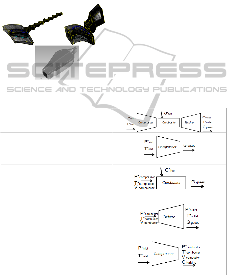
Figure 1: GTE elements models.
2.3 Solution Strategy
Since programs Fluent and Fine Turbo no function
associated start and calculating individual
component alternately executed programs running.
In this case the boundary conditions for a separate
calculation of a unit known in advance, because the
nodes are mutually influence each other (Kulagin,
2002). For example, the temperature field is not
known in advance at the turbine inlet, it necessary to
calculate the combustion chamber. Which in turn
cannot be made because the pressure level is
unknown at the outlet of the combustion chamber, it
determined from the turbine. Therefore, this
calculation can be performed by iterative test passes,
during which the boundary conditions at the nodes
will be updated using the results of the previous
steps (Table 1). Work on this algorithm can be
performed manually or in automatic mode
(Kuz'michev, 1992).
Table 1: Solution strategy.
1. Initially, only pressure and temperature at the inlet
of the compressor, pressure and temperature at the outlet
of the turbine, and fuel consumption are known.
2. Compressor calculation in Numeca Fine Turbo
with mass flow taken from the output of the turbine. As a
result, the output of the compressor is determined by the
field of pressure, temperature, velocity and turbulence
parameters.
3. Combustor calculation in the Ansys Fluent. Input
field parameters (pressure, temperature, velocity) takes
from step 2, on the outlett - mass flow from the output of
the turbine. As a result, the output pressure field is
determined by the burner of temperature, speed and
turbulence parameters.
4. Turbine calculation in Numeca Fine Turbo. Input
field parameters takes from previous step, and the outlet -
output parameters GTE. In this step, we obtain the real
value of air flow through engine by choking nozzle guide
vanes. Next calculations are performed with the adjusted
value of the flow.
5. Compressor calculation in Numeca Fine Turbo
with updated mass flow rate and the outlet field
parameters taken from the combustor calculation (step 3).
As a result, compressor discharge pressure is determined
by the new field of temperatures, velocities and turbulent
flow.
SeparatedComputationoftheWholeJetEngineWorkflow
275

Repetition is performed with st. 3 with the only
difference being that at the boundaries of nodes , as
the boundary conditions are not acceptable uniform
parameter field , and the field is taken from the
calculation node connectivity . Repetition continue
as long as the parameters of the nodes on the borders
will not cease to change significantly. This means
that a stable equilibrium is attained at the boundaries
of nodes , i.e. mutual influence on each other node
set, in other words are found on the boundaries of
such parameters under which the correct modeling
nodes simultaneously on both sides of the border.
Upon completion of this phase of the simulation are
only GTE agreed gasdynamic parameters of
Upon
completion of this phase of the simulation are only
GTE agreed gasdynamic parameters of GTE. It
remains only to ensure proper connectivity modeling
capacity of the compressor and turbine, because they
are mounted on the same shaft , and this is achieved
by giving them equal speed. However, cases are
possible inequality of the compressor and the
turbine, for example, due to the increased heat of the
GTE in the case of the turbine generates more than
the compressor consumes the simulated speed. This
may occur as a consequence computational error
(excessive heat due to inaccurate calculation of
combustion processes), and because of invalid
mode, causing inconsistency really work sites
(Ivliev, 1977). For instance, if too high the amount
of fuel entering the combustion chamber, it is natural
for the turbine flows more energy. In the case of a
real experiment in this case the inequality works
turbine and compressor causes an increase in rotor
speed, increasing the energy consumed by the
compressor, turbine and reduction rotor speed at a
level ensuring consistency of work sites. However,
the settlement program does not automatically
change the speed of the rotor. Therefore, such a
process can be modeled by hand or using scripts
from performing the following sequence of actions:
1. Calculation GTE initial predetermined shaft
speed.
2. Analysis of the results, the definition of torque
difference compressor and turbine ΔM = Mt + Mc (
Mt and Mc are of opposite sign).
3. Depending on the sign ΔM predetermined
increase or decrease the rotor speed and repetition of
the algorithm to st.1 until ΔM decreases to a
predetermined level of error.
In the case of calculation of GTE on the mode
specified TK , such as takeoff or cruising , speed is
set and cannot be edited . In this case the
equalization moments can only be done by changing
the Mt by correcting the amount of fuel supplied to
the combustion chamber performed manually or by
using scripts on a similar algorithm. If the same
amount of fuel is also given ( eg on the conditions of
the experiment) , then because of the lack of degrees
of freedom of the rotor unbalance moments
unavoidably for this model is only a consequence of
computational error: incorrect definition of
resistance paths of the compressor and turbine , or
heat during combustion (eg in the experiment is
incomplete combustion. in this case, the mismatch of
the nodes can be eliminated only by a change
(specification) model: selection and correction
models of turbulence, combustion spray, etc.
2.4 The Problems of Matched Models
For modeling the engine needs to be linked
following parameters:
1) Fluid. In Numeca user can specify only a
single component of fluid. Therefore, the
compressor calculated on the pure air in the
combustion chamber Fluent - a mixture of air, fuel,
and products, and a turbine in Numeca - on the
working fluid with parameters (specific heat,
viscosity, etc.) of a mixture which has been obtained
at the output of the burner.
2) Transfer of parameter fields between elements
of GTE from one node to another is done by
averaging the parameters in the circumferential
direction. Application of the radial distribution of
the flow parameter in Fluent performed with User-
Define Functions (UDF). Each function reads from
the file allocation parameters adjustment channel
obtained from the calculation of the compressor and
turbine in Numeca. Then calculated the radius of the
center of each computational cell at the border and is
calculated corresponding to the radius parameter
using linear interpolation (Fig. 2).
2.4.1 Fluid
To calculate the flow in the turbine must set the
parameters of the working body. In this case the
turbine working fluid is a mixture of gases at the
outlet of the combustion chamber of the following
composition.
Accordingly, the main contribution to the
composition of the mixture produces four
components. Mixture parameters are calculated
according to the law of an ideal mixture:
С = ΣСi·mi
M = ΣMi·mi
R = ΣRi·mi
SIMULTECH2014-4thInternationalConferenceonSimulationandModelingMethodologies,Technologiesand
Applications
276
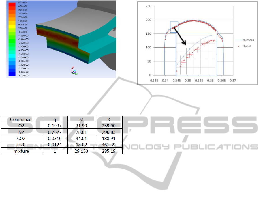
Figure 2: Circumferential velocity field at the inlet of the
combustion chamber.
Table 2: Fluid component properties for turbine
computation.
All the data is entered when setting tasks
Numeca. Parameters are set via the working fluid
and the gas constant profile Cp.
2.4.2 Transfer of Parameter Fields between
Elements of GTE
At the entrance to the combustion chamber defined
input conditions taken from the compressor ,
calculated in Numeca. This is the total pressure ,
static pressure initialization, flow direction ( the
direction vector components of the velocity), the
turbulence parameters (k and epsilon), the total
temperature. After task information flow
characteristics at the inlet and outlet of the
combustion chamber deduced from Fluent for
subsequent use in Numeca compressor and turbine
calculating.
To assess the accuracy of the simulation task was
compared to the input parameter profiles border with
profiles that have been set . Fig . 3 shows a
comparison of the original and the obtained profile
value to the velocity magnitude at the inlet. The
initial profile obtained from Numeca, consists of 59
points connected by a line with 589 imposed points
obtained from Fluent.
Figure 3: Comparison of the Fluent and Fine Turbo
velocity profile at the combustor inlet.
By coincidence of the results obtained with the
original profile settings, you can judge what a way
to set options at the entrance into the combustion
chamber through the UDF works correctly. The
difference is mainly due to the net error of
calculation, and altered flow value. In the
compressor consumption are not explicitly asked,
and the boundary conditions in Numeca were taken
with the design calculation. Therefore, the value of
speed, obtained by "blowing" of the compressor and
combustor, are slightly different. This caused the
difference between the static pressure at the inlet
into the combustion chamber. Data inaccuracies
should be taken into account when further specifying
the calculation of the core. Thus, to calculate the
parameters in the turbine must obtain profiles of the
parameters at the output of the combustion chamber.
Due to the fact that in Fluent in the boundary
layer of the cell is larger than Numeca, the range of
profiles obtained from Fluent, is narrower than the
grid in Numeca. Accordingly, when imposing such a
profile the program will have to extrapolate the
extreme values. Often due to high gradients on the
edges of the profile of such extrapolation is
extremely revisione parameter values, which leads to
the impossibility of calculating. This extrapolation is
required as a rule on 0,001-0,002 mm (first three to
four layers of cells in Numeca). This problem can be
avoided if "stretch" profile on the desired band.
While the stretch factor is extremely small and does
not affect the values in the main part of the profile.
2.5 Results of Calculations Stages
As a result of the first iteration of entire engine
calculation were written in Table 3. ΔM was
approximately 7%.
SeparatedComputationoftheWholeJetEngineWorkflow
277
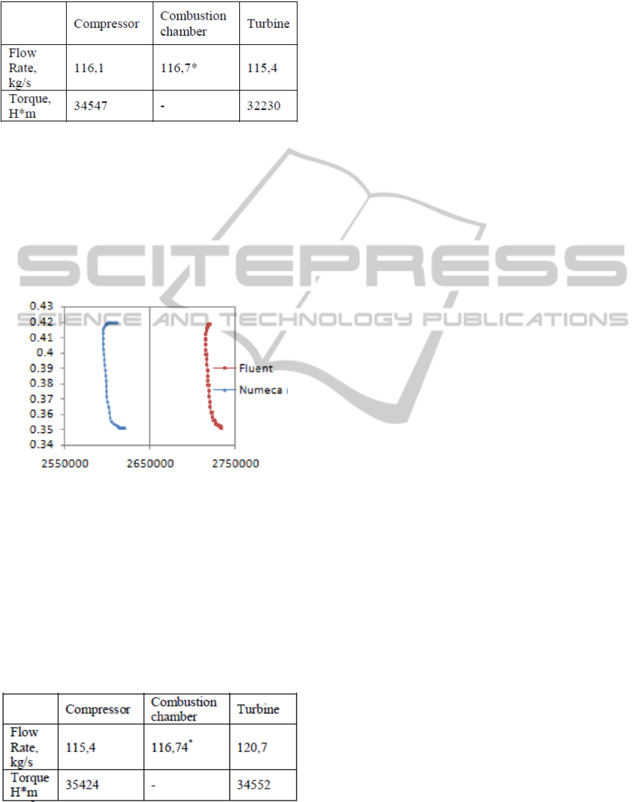
Table 3: Fluid component properties for turbine
computation.
* the flow rate in the combustion chamber differ by an amount of
fuel consumption.
Evident that the correction of the flow through
the combustor section plenum defined by the outlet
of the combustion chamber " shifted " to provide a
desired flow . In the case of a true mass flow rate
(next iteration), the profile is specified without
shear, ie is identical.
After calculating the turbine profiles were
obtained following parameters.
Figure 4: Profile static pressure at the turbine inlet.
Recalculation of the compressor, and then the
combustor at the new flow with the following results
(Table 4). ΔM was approximately 2.5%.
From the values of two iterations can be
interpolating or extrapolating the curves in Fig.4
Choose equal fuel combustion chamber and turbine.
This value is used at the third iteration.
Table 4: Fluid component properties for turbine
computation.
* the flow rate in the combustion chamber differ by an amount of
fuel consumption.
Calculated compressor flow rate equal to minus
the selected fuel. After that, with a given flow rate is
calculated combustion chamber, and then - turbine.
Thereafter, the results of last and penultimate
iteration again chosen fuel for the next iteration.
This process is repeated until, as the costs and are
equal to a sufficient degree of accuracy.
After spending information torque reduction is
performed and the compressor turbine by adjusting
the amount of fuel supplied to the combustor. This
method mimics the automatic control system - a
correction fuel supply quantity to maintain the
desired speed. (Similarly, we can perform the
reduction side, changing the frequency of rotation at
a constant amount of fuel supplied, ie simulate self
promotion engine). As the amount of fuel supplied
to the combustion chamber, changing the
temperature field in the turbine, and changes its
torque. If this flow rate is also changed, then it
generate corrections as described above. After the
information is currently executing control
recalculation of all nodes of the gasifier. If the
parameter field on the adjacent borders gasifier units
are not equal, the calculation continues until the
configuration profiles will not cease to evolve over
iterations.
3 CONCLUSIONS
In this work identified significant problems
associated with long bills and needs of
computational resources, the instability of the
solution process, a lot of the assumptions used.
Furthermore estimator conducting this study should
be qualified and equally well-versed in the workflow
all nodes work together nodes GTE thermodynamics
and numerical simulation of gas flow and
combustion processes.
However, gas-dynamic modeling joint workflow
engine has great potential because it allows to model
the mutual influence of nodes on each other, to
explore the effects of changing operating conditions
or geometric shapes of the elements of the flow on
the characteristics of GTE and all the nodes that are
included in it. For this reason, investigations in this
direction should continue.
ACKNOWLEDGEMENTS
This work was financially supported by the
Government of the Russian Federation (Ministry of
SIMULTECH2014-4thInternationalConferenceonSimulationandModelingMethodologies,Technologiesand
Applications
278

education and science) based on the Government of
the Russian Federation Decree of 09.04.2010 № 218
(theme code 2013-218-04-4777).
REFERENCES
Claus, R.W., Townsend, S., A review of high fidelity, gas
turbine engine simulations. //ICAS 2010, 2010. 27th
International Congress of The Aeronautical Sciences.
Schluter, J., Wu, X., Pitsch, H., Kim, S., Alonso, J.,
Integrated simulations of a compressor/combustor
assembly of a gas turbine engine.//ASME Turbo Expo
2005, GT2005-68204.
Turner, M., “Lessons Learned from the GE90 3D Full
Engine Simulation,” AIAA-2010-1606, Jan.2010.
Turner, M., Reed, J.A., Ryder, R., Veres, J.P.,
“Multifidelity Simulation of a Turbofan Engine with
Results Zoomed into Mini-Maps for a Zero-D Cycle
Simulation,”ASME GT2004-53956.
Krivcov, A.V. Shabliy, L.S., Baturin, O.V., Kolmakova,
D.A., Coupled CFD simulation of gas turbine engine
core // Proceedings of the 4:th CEAS Conference in
Linkoping, 2013. pp. 719-725.
Kulagin, V.V. Teorija raschet i proektirovanie
aviacionnyh dvigatelej i jenergeticheskih ustanovok:
Uchebnik. Osnovy teorii GTD. Rabochij process i
termogazodinamicheskij analiz. Kn.1. Sovmestnaja
rabota uzlov vypolnennogo dvigatelja i ego
harakteristiki. Kn.2. [Tekst]/ V.V. Kulagin – M.:
Mashinostroenie, 2002. – 616 s.
Kuz'michev, V.S., Maslov, V.G., Morozov, M.A.,
Novikov, O.V. Expert assessment of the scientific and
engineering level of an aircraft gas turbine engine
design// (1992) Izvestiya Vysshikh Uchebnykh
Zavedenij. Aviatsionnaya Tekhnika (4) PP. 50 - 55
Ivliev, A.V., Knysh, Yu.A., Lukachev, V.P. Influence of
Combustion Chamber Geometry on Toxic Compound
Emissions// (1977) Sov Aeronaut 20 (1) PP. 44 – 48.
http://www.ansys.com/.
SeparatedComputationoftheWholeJetEngineWorkflow
279
