
Adaptive Control of Position Compensation for Cable-Conduit
Mechanisms Used in Flexible Surgical Robots
T. N. Do
1
, T. Tjahjowidodo
1
, M. W. S. Lau
2
and S. J. Phee
1
1
School of Mechanical and Aerospace Engineering, Nanyang Technological University, Robotic Research Centre, 50
Nanyang Avenue, Singapore, 639798, Singapore
2
Newcastle University International Singapore (NUIS),
180 Ang Mo Kio Avenue 8, Block P, Room 220, Singapore 569830, Singapore
Keywords:
Surgical Robot, Cable-Conduit, Nonlinear Control, Adaptive Laws, Flexible Endoscope.
Abstract:
Natural Orifice Transluminal Endoscopic Surgery (NOTES) is a method that allows for performing complex
operations via natural orifices without skin incisions. Its main tool is a flexible endoscope. Cable-Conduit
Mechanisms (CCMs) are often used in NOTES because of its simplicity, safety in design, and easy trans-
mission. Backlash hysteresis nonlinearities between the cable and the conduit pose difficulties in the motion
control of the NOTES system. It is challenging to achieve the precise position of robotic arms when the slave
manipulator inside the humans body. This paper presents new approaches to model and control for pairs of
CCMs. It is known that the change of cable-conduit configuration will affect the backlash hysteresis non-
linearities. To deal with such change, a new nonlinear and adaptive control scheme will be introduced. The
backlash hysteresis parameters are online estimated under the assumption of availability of output feedback
and unknown bound of nonlinear parameters. To validate the proposed approach, a prototype of single-DOF-
Master-Slave system, which consists of a master console, a telesurgical workstation, and a slave manipulator,
is also presented. The proposed compensation scheme is experimentally validated using the designed sys-
tem. The results show that the proposed control scheme efficiently improves the tracking performances of the
system regardless of the change of endoscope configuration.
1 INTRODUCTION
Flexible endoscope is used in minimally invasive
surgery (MIS) to inspect and treat gastrointestinal
(GI) tract disorders without making any abdominal in-
cisions in the patients body (Zhang et al., 2014); (Ott
et al., 2011); (Clark et al., 2012). One of the promis-
ing surgical procedures using flexible endoscopes is
the natural orifice transluminal endoscopic surgery
(NOTES). The flexible endoscope could reach poten-
tial surgical site via natural orifices or small incisions
and perform flexible tasks with the attached robotic
arms. A pair of Cable-Conduit Mechanisms (CCMs)
or tendon-sheath mechanisms is often used to actuate
the robotic joints inside the human body by control-
ling each of the degrees of freedom (DOFs) of the
robotic arms. The CCM is preferred over other trans-
mission systems because it can operate in restricted
work spaces and in long, narrow, and tortuous paths.
Compared with other mechanisms like cable-pulley or
hyper-redundant mechanism, CCM offers high pay-
load and greater flexibility. However, the main draw-
back in the CCM is the presence of nonlinear fric-
tion and backlash hysteresis. Control of precise mo-
tion of the robotic arms is prominently a challenging
issue in the use of such mechanism. Recently, vari-
ous models for the CCM have been proposed and dis-
cussed to enhance performances of the CCM. Many
researchers (Kaneko et al., 1992); (Palli et al., 2012);
(Sun et al., 2014); (Chiang et al., 2009); (Phee et al.,
2010) used lumped mass model elements to charac-
terize the tendon-sheath transmission. In other ap-
proaches, some authors (Agrawal et al., 2010b) pro-
posed a set of partial differential equations to model
the tendon-sheath nonlinearity using a number of ten-
don elements. However, limitations still exist. Firstly,
if more elements of the CCM are taken into consid-
eration to improve the accuracy, the computation be-
comes more complex. Secondly, a constant preten-
tion for all tendon elements is assumed. Thirdly, the
models need the information of sheath configuration
along the endoscope. Lastly, discontinuous phenom-
ena still exist in the model approaches due to the use
of Coulomb friction model. Although Do and his col-
110
Do T., Tjahjowidodo T., Lau M. and Phee S..
Adaptive Control of Position Compensation for Cable-Conduit Mechanisms Used in Flexible Surgical Robots.
DOI: 10.5220/0005114701100117
In Proceedings of the 11th International Conference on Informatics in Control, Automation and Robotics (ICINCO-2014), pages 110-117
ISBN: 978-989-758-039-0
Copyright
c
2014 SCITEPRESS (Science and Technology Publications, Lda.)
leagues (Do et al., 2013a), (Do et al., 2013b), (Do
et al., 2014b), and (Do et al., 2014a) introduced novel
dynamic friction model to overcome the discontinu-
ity for estimated force feedback, no motion control
schemes were introduced to compensate for the posi-
tion errors.
It has been known that the backlash hysteresis pro-
file varies with the endoscope configuration (Bardou
et al., 2012),(Kesner and Howe, 2011), (Kesner and
Howe, 2014). To achieve accurate tracking control,
two approaches are usually considered. The first one
is that feedback of the robotic joints is available and
the closed-loop control is used. Online estimation of
backlash hysteresis parameters with adaptive control
laws is applied regardless of the changes of configu-
ration. In this case, electromagnetic tracking system
or image processing methods can be considered as a
potential tool to provide the output feedback (Reilink
et al., 2013). In the absence of the position feedback
during the compensation, feedforward control scheme
should be used. To improve the tracking perfor-
mances using offline learning, a backlash hysteresis
model and compensation control scheme with higher
accuracy and degree of smoothness, and ease of im-
plementation, are desired. For the design of back-
lash compensators, some researchers (Su et al., 2000);
(Hu et al., 2013) used a very complex nonlinear and
adaptive control algorithm to deal with the nonlinear-
ities under the assumption of available output feed-
back. They indicated that the backlash model given
by authors in (Tao and Kokotovic, 1995) is not suit-
able for the system control as the backlash function is
discontinuous. Agrawal and his colleagues (Agrawal
et al., 2010a) used a smooth inverse of backlash hys-
teresis model to compensate for the error. However, a
smooth inverse model, a switching law for the veloc-
ity, and output feedback were needed. Do and his col-
leagues (Do et al., 2014c) used a direct inverse model-
based feedforward to compensate for the position er-
ror in a single CCM. The compensator uses the direct
inverse structure that does not require complex inver-
sion of backlash hysteresis model and allows for easy
implementations (Rakotondrabe, 2011); (Do et al.,
2014c), (Hassani et al., 2014); (Minh et al., 2010), and
(Vo-Minh et al., 2011). However, the change of cable-
conduit mechanism has not been considered yet. To
deal with this challenge, a direct control algorithm
is developed regardless of the construction of inverse
model (Cai et al., 2013); (Zhang et al., 2014). In this
paper, new adaptive control laws are presented with-
out using any inverse model for the compensation.
The control scheme in this paper allow for captur-
ing the backlash hysteresis nonlinearities and efficacy
of enhancing tracking performances regardless of the
curvature and sheath angles. Compare to the other
approaches (Agrawal et al., 2010a); (Bardou et al.,
2012),(Kesner and Howe, 2011), (Kesner and Howe,
2014); (Do et al., 2014c), where the backlash hystere-
sis or the bound of parameters must be known in ad-
vance, in our schemes, their bounds are unknown and
online estimated during the compensation. To vali-
date the proposed approach, a dedicated single degree
of freedom of a Master-Slave system is introduced.
The system consists of a master console, actuator
housing, and a slave manipulator. This type of system
has been presented in NOTES systems like MASTER
(Phee et al., 2010), (Abbott et al., 2007). Using the
designed Master-Slave system, the proposed schemes
are experimentally carried out to validate real surgical
tasks such as gripping a determined object. The rests
of this paper are organized as follow: In section 2,
an overview of NOTES system and the transmission
property of a pair of TSM are introduced. The de-
sign of the Master-Slave system for validation, which
contains the master console, motor housing and slave
manipulator, is introduced in this section. In addi-
tion, the development of nonlinear and adaptive con-
trol laws will be given. Experimental demonstration
is presented in section 3. Finally, the conclusion is
drawn in section 4.
2 MATERIALS AND METHODS
In order to evaluate the proposed control scheme, a
human-subject platform is introduced. This section
also presents the cable-conduit transmission charac-
teristics and experimental instruments. Nonlinear and
adaptive control laws for enhancing the tracking per-
formance will be also given.
2.1 NOTES System and Cable-Conduit
Characteristics
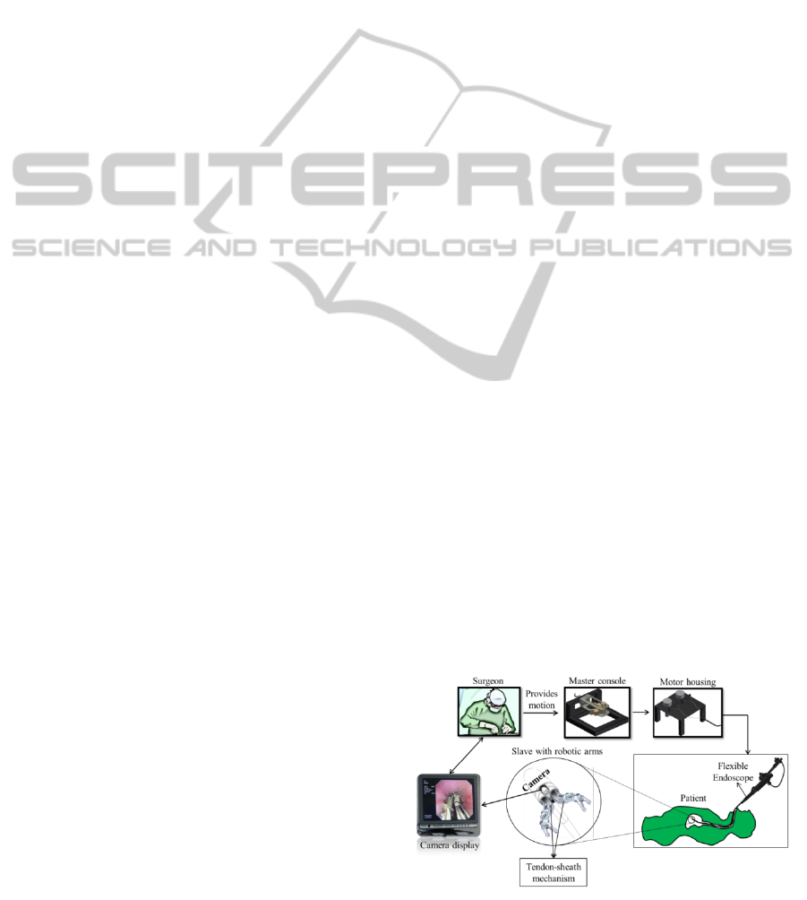
Figure 1: Overview of a NOTES system.
AdaptiveControlofPositionCompensationforCable-ConduitMechanismsUsedinFlexibleSurgicalRobots
111
A typical Natural Orifice Transluminal Endoscopic
Surgery (NOTES) system is illustrated in Fig. 1. Sur-
geons carry out the surgical tasks using a master con-
sole to control the slave manipulator (includes robotic
arms) inside the patients body. The system consists of
a master console, a slave manipulator, and a telesur-
gical workstation (motor housing). One of the main
tools of NOTES is a long and flexible endoscope,
i.e. a flexible shaft with an articulated bending tip
and tool channels to house the robotic arms as well
as a camera (provide visual feedback to the surgeon).
The robotic arms which possess multiple degrees of
freedom (DOFs) are fixed and carried along with the
endoscope to perform demanding surgical procedures
such as suturing and cutting. Triangulation is carried
out at the distal end of the endoscope while actuation
is externally provided.
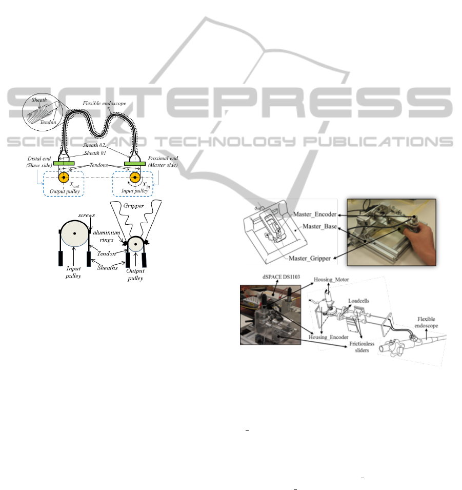
Figure 2: (Upper) Diagram for a pair of CCMs; (Lower)
Ways for connecting cables (tendons) to pulleys.
To control each of the DOFs for the robotic arms,
a pair of CCMs is often used. The pull-pull trans-
missions for the CCMs have been studied in (Kaneko
et al., 1992); (Agrawal et al., 2010b). The upper panel
of Fig. 2 shows the structure of a pair of the CCMs.
x
in
and x
out
denote the displacements at the proximal
end and at the distal end of the system, respectively.
The two cables and conduits are routed along a flex-
ible tube as the endoscope. Suppose that the input
pulley initially rotates in the clockwise direction (pos-
itive velocity-see The upper panel of Fig. 2a). When
the input pulley reverses its motion, the output pulley
does not immediately rotate, which results in a cer-
tain delay. The tension decreases in the previously
tensed cable. The loss of tensions along the conduit,
which due to the gap and friction force between the
cables and the conduits, results in delay for imme-
diate transmission of motion from the input pulley
(proximal end) to the output pulley (distal end). Once
the friction between the cables and the conduit in the
outer loop of the pair of CCMs is overcome, then the
output pulley immediately rotates following the input
pulley. Similar transmission characteristics are de-
scribed for the reversal motion in counter-clockwise.
This behavior of the transmission characteristics of
the CCM is referred to as a backlash hysteresis pro-
file. Note that the dead-band is not considered in this
paper because the cables are always pre-tensed. From
aforementioned descriptions, cable-conduit transmis-
sion can be approximately modeled as the backlash
hysteresis where the nonlinear parameters of hystere-
sis profile depend on the cable-conduit configuration.
2.2 Experimental protocol
In this section, we introduce a dedicated experimental
setup of a single-DOF Master-Slave system. The sys-
tem consists of a master console, telesurgical work-
station (include actuator housing and dSPACE con-
troller), and a slave manipulator. For illustration, a
slave system with a single-DOF robotic arm is con-
sidered. The overview of NOTES system has been
illustrated in Fig. 1. The mechanism design of a
Figure 3: The master console and motor housing with di-
agrams and real photos:(Upper) Master console with two
DOFs; (Lower) Actuator housing with two motors.
master console with a single-DOF, denoted as Mas-
ter Gripper is presented in The upper panel of Fig.
3a. The master console, which enables the user to
control the robotic arm at the distal end, is an er-
gonomic human-machine interface. In the master
console, one encoder (Master Encoder) is mounted
to the Master Gripper to provide necessary signal
(position-reference trajectory y
r
) to the output pul-
ley with an attached gripper. The encoder is type
of SCA16 from SCANCON. Signal from the Mas-
ICINCO2014-11thInternationalConferenceonInformaticsinControl,AutomationandRobotics
112
ter Encoder will be subsequently sent to the dSPCAE
controller where the data are processed and the cables
and conduits actuation are controlled. The users con-
trol the motions of a gripper mounted on the output
pulley via Master Gripper. The picture of the mas-
ter console is shown in right side of the upper panel
of Fig. 3. The telesurgical workstation (The lower
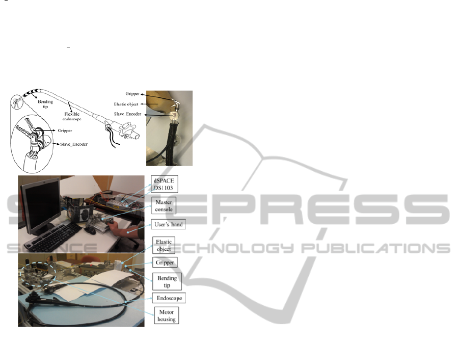
Figure 4: (Upper) Slave manipulator with two DOFs:
(Lower) Photo of experimental setup.
panel of Fig. 3) consists of an actuator housing and
dSPACE DS1103 controller. The controller consists
of the control board, which is programmed via MAT-
LAB Simulink from MathWorks. The signals from
the master console and the robotic arm at distal end
are also acquired to this system. The actuator hous-
ing includes a PITTMAN 8693 DC motors equipped
with high resolution encoder E30. A input pulley,
which actuates the slave joint (gripper with output
pulley) using the CCMs, is also conneted to the mo-
tor. The CCMs are from Asahi Intecc Co. where
the size of the cables is WR7x7D0.27mm with teflon
coated wire ropes and the conduits with a round-wire
coil and inner diameter of 0.36mm and outer diam-
eter of 0.8mm. The length of the two conduits is 2
metre. The two CCMs are routed to follow a flexible
endoscope and are connected to pulleys. At the in-
put pulley, cables are fixed on the pulley using crews
while at the output pulley, cables are fixed on corre-
sponding holes using aluminium rings (see the lower
panel of Fig. 2). In order to record the tensions at
proximal end of the system, two load cells LW-1020-
50 from Interface Corporation are used. They are
mounted on frictionless sliders. The two cables and
two conduits, subsequently, are used to actuate one
of DOFs of the rotation joints. Noting that the ten-
sions at proximal end are used to guarantee the same
pretension when trials are repeated. Fig. 4 depicts
the slave manipulator structure. In the experimental
work, a gripper which is mounted on the tip of the en-
doscope is used as a robotic arm. The two cables are
routed along two conduits passing through a flexible
endoscope. The flexible endoscope, which is a type of
GIF-2T160 from Olympus, Japan, has two tool chan-
nels with a length of 135cm. At each side (proximal
end and distal end), the tendon is attached to corre-
sponding pulleys (see the lower panel of Fig. 2). To
measure the rotational displacement for the gripper
joint at proximal end, a high resolution encoder Type
SCA16 from SCANKON is utilized. The encoder is
connected to the gripper joint via a small cable. The
rotation motion of gripper is recorded by the dSPACE
controller DS1103 via MATLAB environment from
MathWorks.
2.3 Nonlinear and Adaptive Control
An adaptive control law is given in this section to
deal with the change of cable-conduit configuration.
If we consider this change as an unexpected distur-
bance, the nonlinear backlash hysteresis model which
has been described in (Do et al., 2014c) can be rewrit-
ten by:
x
out
= cu
NL
+ D (1)
where D denotes the change of the hysteresis curve
when the cable-conduit configuration varies, u
NL
=
x
in
represents for the control input, x
out
is the output
position.
Before going to the design of control law, some
assumptions are made: (i) the cables are kept at some
suitable pretension in order to avoid the cable slack,
(ii) Output position feedback is used during the com-
pensation, (iii) Uncertain parameter c is positive and
its bound is unknown. Let the positive value D
∗
be the
bound of which is assumed to be unknown. It will be
estimated using the designed adaptive law; α is a pos-
itive parameter. Define a coordinate transformation ω
and n for the system given by Eq. (1) and a tracking
error e
r
as follows:
n =
Z
t
0
(y(τ) − y
r
(τ))dτ
e
r
(t) = y(t) − y
r
(t)
ω = e
r
(t) + α
Z
t
0
e
r
(τ)dτ = ˙n + αn
(2)
The first order derivative of the new variable can
AdaptiveControlofPositionCompensationforCable-ConduitMechanismsUsedinFlexibleSurgicalRobots
113

be expressed by:
˙
ω = α(y − y
r
) + ˙e
r
= α(cu
NL
+ D − y
r
) + ˙e
r
(3)
Denote the inverse of backlash hysteresis slope c
by χ = 1/c, then the estimate of χ and D
∗
will be
stated as
ˆ
χ and
ˆ
D
∗
, respectively. Define
˜
D
∗
= D
∗
−
ˆ
D
∗
as the error estimate bound of disturbance D
∗
. From
Eq. (2) and Eq. (3), the adaptive control law is de-
signed as follows:
u
NL
= −
ˆ
χ(kω + sgn(ω)
ˆ
D
∗
− y
r
+ (1/α) ˙e
r
) (4)
˙
ˆ
χ = δ
1
(kω + sgn
ˆ
D
∗
− y
r
+ (1/α) ˙e
r
)ω (5)
˙
ˆ
D
∗
= δ
2
|ω| (6)
where k, δ
1
,δ
2
are positive parameters that adjust
the controller to force the tracking errors tend to com-
pact sets.
With Eq. (3) to Eq. (6), the following theorem
holds:
Theorem 1. Consider the nonlinear system (Eq. 3)
with uncertainties and satisfies the assumptions (i) to
(iv). The following statements hold under the con-
troller given by Eq. (4) and the update laws given by
Eq. (5) and Eq. (6):
1. The closed loop system results in global stability.
2. The tracking errors e
r
and estimates
ˆ
χ,
ˆ
D
∗
are uni-
formly ultimately bounded (UUB).
Proof : We define the Lyapunov function V as fol-
lows:
V = 0.5ω
2
+ (0.5/µ)(
˜
D
∗
)
2
+ (c/2δ)(
˜
χ)
2
(7)
where
˜
χ = χ −
ˆ
χ is error estimate of χ; µ,δ
are positive parameters. The initial values of func-
tion V is V (0) = 0.5(ω(0))
2
+ (0.5/µ))(
˜
D
∗
(0))
2
+
(c/2δ)(
˜
χ(0))
2
with ω(0),
˜
D
∗
(0),
˜
χ(0) are initial val-
ues of ω,
˜
D
∗
,
˜
χ, respectively.
The derivative of the Lyapunov function given by
Eq. (7) can be obtained by:
˙
V = ω
˙
ω − (1/µ)
˜
D
∗
˙
ˆ
D
∗
− (c/δ)
˜
χ
˙
ˆ
χ = ω(α(cu
NL
+ D
− y
r
) + ˙e
r
) − (1/µ)
˜
D
∗
˙
ˆ
D
∗
− (c/δ)
˜
χ
˙
ˆ
χ (8)
Note that the term u
NL
can be expressed by:
cu
NL
= c
ˆ
χ ¯u = c
ˆ
χ ¯u + ¯u − cχ ¯u = ¯u − c
˜
χ ¯u (9)
where ¯u = −kω − sgn(ω)
ˆ
D
∗
+ y
r
− (1/α) ˙e
r
Replace Eq. (4) to Eq. (6) into Eq. (8), one can
obtain:
˙
V = ω(α(cu
NL
+ D − y
r
) + ˙e
r
) − (1/µ)
˜
D
∗
˙
ˆ
D
∗
− (c/δ)
˜
χ
˙
ˆ
χ = ω(α(−kω − sgn(ω)
ˆ
D
∗
+ y
r
− (1/α) ˙e
r
− c
˜
χ ¯u + D − y
r
) + ˙e
r
) − (1/µ)
˜
D
∗
˙
ˆ
D
∗
− (c/δ)
˜
χ
˙
ˆ
χ
= −αkω
2
− α|ω|
ˆ
D
∗
+ αDω − (1/µ)
˜
D
∗
˙
ˆ
D
∗
− (c/δ)
˜
χ(αδ ¯uω +
˙
ˆ
χ) = −αkω
2
− (c/δ)
˜
χ(αδ ¯uω +
˙
ˆ
χ)
+ (1/µ)
˜
D
∗
(−
˙
ˆ
D
∗
+ αµ|ω|) ≤ −αkω
2
≤ 0 (10)
where δ
1
= αδ,δ
2
= αµ
With the inequality given by Eq. (10), one can see
that the Lyapunov function V is a decreasing function
and bounded from below by zero. From Eq. (10),
one can obtain
˙
V ≤ 0 ⇐⇒ V ≤ V (0) where V (0) =
0.5(ω(0))
2
+ (0.5/µ)(
˜
D
∗
(0))
2
+ (α/2ρ)(
˜
χ(0))
2
≥ 0.
Hence, variables ω,
˜
D
∗
,
˜
χ are also bounded. From (7),
one can obtain 0.5ω
2
≤ V ≤ V (0) or |ω| ≤
p
2V (0).
Two cases for the solutions of n: Case(i) ω = ˙n +
nα ≤
p
2V (0) or n ≤ (n
0
− (1/α)
p
2V (0))e
−αt
+
(1/α)
p
2V (0). There exists t > T > 0 such that
n ≤ (1/α)
p
2V (0) since (n
0
− (1/α)
p
2V (0))e
−αt
→ 0 for any t > T . Case(ii) ω = ˙n + nα ≥ −
p
2V (0)
or n ≥ (n
0
+ (1/α)
p
2V (0))e
−αt
− (1/α)
p
2V (0).
There exists t > T > 0 such that n ≥ −(1/α)
p
2V (0)
since (n
0
+ (1/α)
p
2V (0))e
−αt
→ 0 for any t > T .
For both cases, we have:
|n| ≤ (1/α)
p
2V (0) (11)
With |ω| ≤
p
2V (0) and (11), one can obtain:
| ˙n| − α|n| ≤ |ω| = | ˙n + nα| ≤
p
2V (0)
or | ˙n| ≤ α(1/α)
p
2V (0) +
p
2V (0)
= 2
p
2V (0) (12)
Then, one can verify that the UUB tracking per-
formance for the filter ω and its components n, ˙n = e
r
are guaranteed. It is also demonstrated that the up-
date parameters are guaranteed to be UUB. The proof
is completed here.
Remark 1: It is recommended that relevant valid-
tions based on simulation should be carried out before
doing the practical experiments. Based on the simu-
lation results, optimal parameters can be obtained.
3 REAL-TIME EXPERIMENTAL
VALIDATIONS
For validation purpose, the motion of slave manipu-
lation is investigated by random motions prescribed
from the users movement through the master console.
Fig. 5 illustrates the experimental setup and control
schemes for validation test. In practical validation,
the grasper is required to grip an elastic object that is
controlled using the Master Gripper (see Figs. 3, 4,
and 5). A motion generated by the user via the mas-
ter console is applied to the actuator housing at the
proximal end (see Fig. 5). The Master Encoder and
Slave Encoder are used to record the input and output
motions at corresponding joints using the dSPACE
ICINCO2014-11thInternationalConferenceonInformaticsinControl,AutomationandRobotics
114
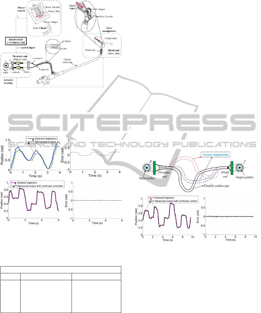
Figure 5: Compensation control structure for the Master-
Slave system.
DS1103. The purpose is to control the output posi-
tion y to follow a desired reference input y
r
as close
as possible.
Figure 6: Compensation results: (Upper) Without com-
pensation; (Lower) With nonlinear control; (Left) Position
tracking; (Right) Tracking error.
Table 1: Quantitative measures for case of nonlinear and
adaptive control.
Position (rad)
Trials Mean squared error Standard deviation
1 0.000276 0.0166
2 0.000196 0.0140
3 0.000286 0.0169
4 0.000244 0.0156
5 0.000227 0.0159
In order to demonstrate the effectiveness of the
proposed nonlinear adaptive scheme, a set of control
parameters are established basing on relevant simula-
tions, i.e. k = 15,α = 5, δ
1
= 10, δ
2
= 10. The signum
function is approximated using sgn(ω) = ω/(|ω| +
0.01) in order to avoid chattering during the imple-
mentation of the controller. The initial values for esti-
mate variables are chosen to
ˆ
χ(0) = 1 and
ˆ
D
∗
(0) = 0.
The experimental validations are carried out five
times (five trials). For illustration purposes, one of the
five trials will be given. Fig. 6 depicts the compensa-
tion results using nonlinear adaptive control scheme
which is illustrated by the proposed structure in Fig.
5. In the case of no compensation control, the mea-
sured position output y always lags to the desired tra-
jectory y
r
. This phenomenon can be seen from the
upper left panel of Fig. 6. When the nonlinear con-
trol scheme is used (see Fig. 5), the measured out-
put y accurately follows the desired trajectory y
r
(see
the left panel of Fig. 6). The relative error under the
nonlinear control scheme is also depicted in the right
panel of Fig. 6. There is a significant reduction from
0.2669 rad peak-to-peak error before compensation to
0.08743 rad peak-to-peak after compensation. Quan-
titative measures of the results in terms of mean error
and standard deviation for each of trials are shown in
Table 1.
Figure 7: Compensation results with disturbance: (Upper)
Random change of configuration; (Lower) Results for non-
linear control; (Left) Position tracking; (Right) Tracking er-
ror.
It is known that the backlash hysteresis profile will
change if the configuration changes. Hence, the per-
formances of proposed control scheme based on the
change of endoscope configuration during the exper-
iments are evaluated and discussed. The endoscope
configuration, which is shown in the upper panel of
Fig. 7, is varied during the experiments. When the
nonlinear adaptive controller is applied (see the lower
panel of Fig. 7), the phase lag and tracking error are
almost around 0.09743 rad peak-to-peak. It can be
concluded that the proposed control can adapt to any
change of the endoscope configuration.
AdaptiveControlofPositionCompensationforCable-ConduitMechanismsUsedinFlexibleSurgicalRobots
115

4 CONCLUSIONS
This paper introduces a new adaptive control scheme
to enhance the tracking performances for a flexible
endoscopic system using cable-conduit mechanisms.
The proposed control laws are able to deal with non-
linearities in the presence of uncertainties and dis-
turbances. Unlike current approaches of the cable-
conduit control, our control scheme has efficiently
reduced the tracking error and robustness. Experi-
mental validations have been carried out using a real
master-slave system to evaluate the controller perfor-
mances. Comparisons between the proposed model
and the experimental data show a good agreement.
It has been demonstrated that the model approach
works well on a real surgical device (Master-Slave
system) in NOTES system to carry out the task of
gripping a real object. It has also been indicated
that the proposed scheme is able to track the de-
sired reference signal regardless of the configuration
of the endoscope. In addition, no knowledge of exact
backlash hysteresis parameters is required. The pro-
posed control scheme has opened potential benefits to
other flexible endoscopic system for enhancing track-
ing performances of precise motion. Future activities
will be conducted the validations for higher degrees
of freedom of flexible endoscopic systems. In addi-
tion, in-vivo on live animal and human will be carried
out for further validations.
REFERENCES
Abbott, D., Becke, C., Rothstein, R., and Peine, W.
(2007). Design of an endoluminal notes robotic sys-
tem. In IEEE/RSJ International Conference on Intel-
ligent Robots and Systems, IROS,, pages 410–416.
Agrawal, V., Peine, W., Yao, B., and Choi, S. (2010a).
Control of cable actuated devices using smooth back-
lash inverse. In IEEE International Conference on
Robotics and Automation (ICRA), pages 1074–1079.
Anchorage, AK.
Agrawal, V., Peine, W. J., and Yao, B. (2010b). Modeling
of transmission characteristics across a cable-conduit
system. IEEE Transactions on Robotics, 26(5):914–
924.
Bardou, B., Nageotte, F., Zanne, P., and De Mathelin, M.
(2012). Improvements in the control of a flexible en-
doscopic system. In IEEE International Conference
on Robotics and Automation (ICRA), pages 3725–
3732. Saint Paul, MN.
Cai, J., Wen, C., Su, H., and Liu, Z. (2013). Robust adaptive
failure compensation of hysteretic actuators for a class
of uncertain nonlinear systems. IEEE Transactions on
Automatic Control, 58(9):2388–2394.
Chiang, L. S., Jay, P. S., Valdastri, P., Menciassi, A.,
and Dario, P. (2009). Tendon sheath analysis for
estimation of distal end force and elongation. In
IEEE/ASME International Conference on Advanced
Intelligent Mechatronics (AIM), pages 332–337.
Clark, M. P., Qayed, E. S., Kooby, D. A., Maithel, S. K., and
Willingham, F. F. (2012). Natural orifice translumenal
endoscopic surgery in humans: a review. Minimally
invasive surgery, 2012.
Do, T. N., Tjahjowidodo, T., Lau, M. W. S., and Phee, S. J.
(2013a). Dynamic friction model for tendon-sheath
actuated surgical robots: modelling and stability anal-
ysis. In ISRM 2013-Proceedings of the 3rd Inter-
national Symposium on Robotics and Mechatronics,
pages 302–311. Singapore.
Do, T. N., Tjahjowidodo, T., Lau, M. W. S., and Phee, S. J.
(2013b). Nonlinear modeling and parameter identi-
fication of dynamic friction model in tendon sheath
for flexible endoscopic systems. In ICINCO 2013-
Proceedings of the 10th International Conference on
Informatics in Control, Automation and Robotics,
pages 5–10. Reykjavik, Iceland.
Do, T. N., Tjahjowidodo, T., Lau, M. W. S., and Phee, S. J.
(2014a). Dynamic friction-based force feedback for
tendon-sheath mechanism in notes system. Interna-
tional Journal of Computer and Electrical Engineer-
ing, 6(3):252–258.
Do, T. N., Tjahjowidodo, T., Lau, M. W. S., and Phee, S. J.
(2014b). An investigation of friction-based tendon
sheath model appropriate for control purposes. Me-
chanical Systems and Signal Processing, 42(1-2):97–
114.
Do, T. N., Tjahjowidodo, T., Lau, M. W. S., Yamamoto, T.,
and Phee, S. J. (2014c). Hysteresis modeling and po-
sition control of tendon-sheath mechanism in flexible
endoscopic systems. Mechatronics, 24(1):12 – 22.
Hassani, V., Tjahjowidodo, T., and Do, T. N. (2014). A
survey on hysteresis modeling, identification and con-
trol. Mechanical Systems and Signal Processing,
49(1):209–233.
Hu, C., Yao, B., and Wang, Q. (2013). Performance-
oriented adaptive robust control of a class of nonlinear
systems preceded by unknown dead zone with com-
parative experimental results. IEEE/ASME Transac-
tions on Mechatronics, 18(1):178–189.
Kaneko, M., Paetsch, W., and Tolle, H. (1992). Input-
dependent stability of joint torque control of tendon-
driven robot hands. IEEE Transactions on Industrial
Electronics, 39(2):96–104.
Kesner, S. and Howe, R. (2011). Position control of motion
compensation cardiac catheters. IEEE Transactions
on Robotics, 27(6):1045–1055.
Kesner, S. B. and Howe, R. D. (2014). Robotic catheter
cardiac ablation combining ultrasound guidance and
force control. The International Journal of Robotics
Research, 33(4):631–644.
Minh, T. V., Kamers, B., Tjahjowidodo, T., Ramon, H.,
and Van Brussel, H. (2010). Modeling torque-angle
hysteresis in a pneumatic muscle manipulator. In
IEEE/ASME International Conference on Advanced
Intelligent Mechatronics (AIM), pages 1122–1127.
ICINCO2014-11thInternationalConferenceonInformaticsinControl,AutomationandRobotics
116

Ott, L., Nageotte, F., Zanne, P., and de Mathelin, M.
(2011). Robotic assistance to flexible endoscopy by
physiological-motion tracking. IEEE Transactions on
Robotics, 27(2):346–359.
Palli, G., Borghesan, G., and Melchiorri, C. (2012). Mod-
eling, identification, and control of tendon-based ac-
tuation systems. IEEE Transactions on Robotics,
28(2):277–290.
Phee, S. J., Low, S., Dario, P., and Menciassi, A. (2010).
Tendon sheath analysis for estimation of distal end
force and elongation for sensorless distal end. Robot-
ica, 28(07):1073–1082.
Rakotondrabe, M. (2011). Bouc-wen modeling and inverse
multiplicative structure to compensate hysteresis non-
linearity in piezoelectric actuators. IEEE Transactions
on Automation Science and Engineering, 8(2):428–
431.
Reilink, R., Stramigioli, S., and Misra, S. (2013). Image-
based hysteresis reduction for the control of flexible
endoscopic instruments. Mechatronics, 23(6):652–
658.
Su, C.-Y., Stepanenko, Y., Svoboda, J., and Leung, T.
(2000). Robust adaptive control of a class of nonlinear
systems with unknown backlash-like hysteresis. IEEE
Transactions on Automatic Control, 45(12):2427–
2432.
Sun, Z., Wang, Z., and Phee, S. J. (2014). Elongation mod-
eling and compensation for the flexible tendon–sheath
system. IEEE/ASME Transactions on Mechatronics,
19(4):1243–1250.
Tao, G. and Kokotovic, P. (1995). Adaptive control of sys-
tem with unknown output backlash. IEEE Transac-
tions on Automatic Control, 40(2):326–330.
Vo-Minh, T., Tjahjowidodo, T., Ramon, H., and Van Brus-
sel, H. (2011). A new approach to modeling hysteresis
in a pneumatic artificial muscle using the maxwell-
slip model. IEEE/ASME Transactions on Mechatron-
ics, 16(1):177–186.
Zhang, Z., Xu, S., and Zhang, B. (2014). Asymptotic track-
ing control of uncertain nonlinear systems with un-
known actuator nonlinearity. IEEE Transactions on
Automatic Control, 59(5):1336–1341.
AdaptiveControlofPositionCompensationforCable-ConduitMechanismsUsedinFlexibleSurgicalRobots
117
