
Development of a Parallel Link Arm for Object Handling by Wheeled
Mobile Robot
Toyomi Fujita
1
and Hiroshi Sugawara
2
1
Department of Electronics and Intelligent Systems, Tohoku Institute of Technology,
35-1 Yagiyama Kasumi-cho, Taihaku-ku, Sendai 982-8577, Japan
2
Renesas Design Corp., 413 Mizuhara, Itami, 664-0005, Japan
Keywords:
Parallel Link Mechanism, Mobile Robot, Handling Task.
Abstract:
This paper presents a parallel link arm for a wheeled mobile robot. A parallel mechanism is useful for a
mobile robot because it has more advantages on high output power than serial link. Conventional parallel
mobile manipulators have not been able to perform handling task such as picking up an object on the floor.
Developed parallel link arm in this study has a hand which directs downward. It is mounted on the robot with
the link for swinging so that it is able to carry an object with handling in wide area. This paper describes
development of the parallel link arm and analyses its kinematics. We also consider basic motions of the arm
for object handling tasks. Experimental results demonstrated the usefulness of developed parallel link arm for
object handling tasks by a wheeled mobile robot.
1 INTRODUCTION
A lot of manipulation arm have been developed for
a mobile robot to perform object handling tasks with
movement. Although the most of them have serial
link structure, there are some problems on this type:
it is difficult to handle heavy object, some errors oc-
cur with respect to hand position in a motion. On
the other hand, parallel link structure has some advan-
tages such as high stiffness and higher output power
at the end effector than serial link structure. Even
though parallel link is not able to move in wide area, it
is useful for mobile robot because the robot can move
to desired position by itself so that it covers the area
for manipulation to compensate the weakness of par-
allel link with utilizing its advantages.
Based on this consideration, some studies have
presented manipulators having parallel mechanism
for a mobile robot. For example, Li et al. (Li
et al., 2006) presented a mobile parallel manipula-
tor which is composed by a wheeled mobile robot
with a DELTA parallel robot. Horin et al. (Horin
et al., 2006) presented a parallel mechanism which
was mounted on three independent carts. Yamawaki
et al. (Yamawaki et al., 2004) presented a mobile
parallel robot in which a parallel mechanism was
mounted on tracked mobile robot. Graf and Dill-
mann (Graf and Dillmann, 1997) proposed a mobile
robot on which a Stewart platform was mounted to
compensate the unwanted accelerations. Decker et al.
(Decker et al., 2001) presented a Gough-Stewart Plat-
form mounted on a mobile robot. Shoval and Shoham
(Shoval and Shoham, 2001) proposed a mobile six-
DOF parallel manipulator which was used with a 3-
legs robot. These types are useful for transportation
of an object. However, these are not able to perform
handling task such as picking up an object on the floor
or ground.
In this study, we consider that the robot performs a
handling task such as picking up by itself and present
a novel type of a mobile parallel manipulator in which
a hand directs to the ground to be suitable for object
handling tasks. In addition, presented type has an-
other link for swinging the parallel link arm in the
right and left directions to get the working space large.
This mechanism enables the robot to accomplish han-
dling tasks in small space such as narrow paths with-
out moving itself as possible.
This paper consists of the following sections: Sec-
tion 2 describes the design and development of the
parallel link arm. Section 3 explains analysis of kine-
matics of the arm. Section 4 shows basic motions for
handling tasks. Section 5 employs fundamental ex-
periments for basic motions. Finally Section 6 gives
conclusions.
592
Fujita T. and Sugawara H..
Development of a Parallel Link Arm for Object Handling by Wheeled Mobile Robot.
DOI: 10.5220/0005116905920598
In Proceedings of the 11th International Conference on Informatics in Control, Automation and Robotics (ICINCO-2014), pages 592-598
ISBN: 978-989-758-040-6
Copyright
c
2014 SCITEPRESS (Science and Technology Publications, Lda.)
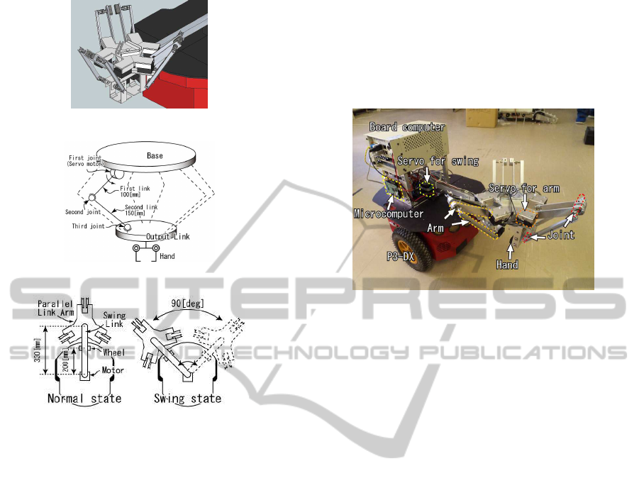
Figure 1: Concept of parallel link arm on a mobile robot
Figure 2: Mechanism of parallel link.
Figure 3: Concept of swing mechanism.
2 DEVELOPMENT OF
PARALLEL LINK ARM
Figure 1 shows a concept of the parallel link arm
which is mounted on a wheeled mobile robot. We
adopted HEXA-type parallel mechanism (Pierrot
et al., 1990) for the arm because this type has six-
DOF and is able to move fast. A hand-unit directed
to downward is also attached to the bottom of the par-
allel link arm so that the robot manipulate an object
on the floor. In addition, we devised a swing link to
change the direction of the arm. Pioneer P3-DX is
used as the mobile platform.
Figure 2 shows mechanism of developed parallel
link arm. The parallel mechanism has six link-units.
Each link-unit consists of three joints and two links.
It is attached to the base and hand-unit at both ends.
The first link has 100 [mm] and the second link has
150 [mm] in length. The first joint, which is attached
to the base, is active revolute joint. The second and
third joints are passive and a universal joint is used
for each. The hand-unit has two actuators to open
and close. It is able to grasp an object which has 100
[mm] in height and 50 [mm] in wide. Kondo KRS-
2552RHV is used for these eight actuators.
We have designed the base, hand-unit, and link-
units using Autodesk AutoCAD. In machining them,
we have generated tool-path from the CAD data using
CAM software JMM-TOOL. From the tool-path, alu-
minum boards which have 2 or 3 [mm] in thickness
have been cut by Originalmind CNC KitMill BT200 .
Figure 4: Robot system with developed parallel link arm.
Figure 3 shows mechanism of the swing link and
concept of swinging. The parallel link arm is fixed at
an end of the swing link. Another end is connected to
a motor Kondo KRS-6003HV mounted at the center
of top plate of P3-DX. The swing link has 330 [mm]
in length so that the parallel link unit protrudes 110
[mm] ahead of the robot. A passive wheel is attached
in the bottom of the swing link at 200 [mm] from the
center of P3-DX to support the weight of parallel link
unit. This mechanism enables the robot to change di-
rection of the parallel link arm in 90 degrees as shown
in the right panel of Fig. 3.
Figure 4 shows an overview of developed system
of parallel link arm on the robot. The weight of the
parallel link arm is 1.5 [kg] and that of the whole
robot system is 20.5 [kg]. A board computer Interface
PCI-B02PA16 and a 32-bit microcomputer Renesas
RX621 are used for controlling whole robot system
and parallel link arm respectively. They are mounted
on the rear part of the top plate of P3-DX to be counter
weight. Simple computation of moment confirmed
that the maximum weight of object attached to the
parallel link arm is 24.8 [kg].
3 KINEMATIC ANALYSIS
3.1 Kinematic Model of Arm
Figure 5 shows a kinematic model of a link-unit with
the base, hand-unit, and swing link. We define right-
hand coordinate systems for them. Σ
B
(x
B
, y
B
, z
B
)
is the base coordinate system at the center of the
base. Its orthogonal unit vectors are x
B
, y
B
, and
DevelopmentofaParallelLinkArmforObjectHandlingbyWheeledMobileRobot
593
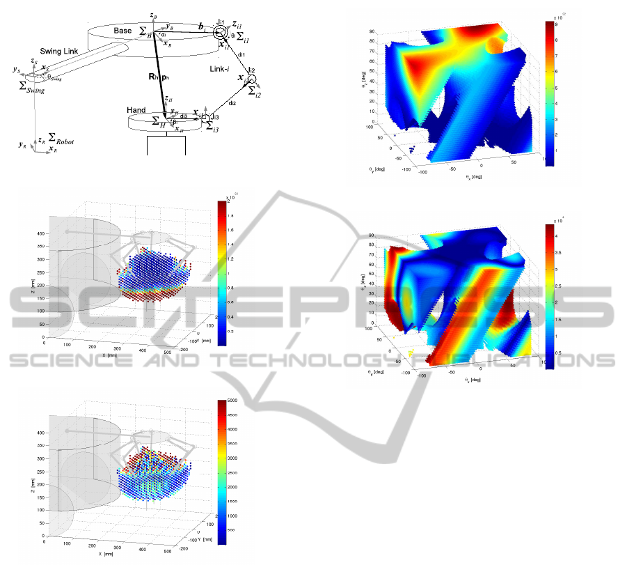
Figure 5: Kinematic model of link systems.
Figure 6: n
θ
(norm of J
θ
) to hand positions.
Figure 7: n
h
(norm of J
h
) to hand positions.
z
B
. Σ
H
(x
H
, y
H
, z
H
) is the hand coordinate system
at the top center of the hand-unit, Σ
i1
(x
i1
, y
i1
, z
i1
)
(i = 1, ..., 6) is the coordinate systems at the ac-
tive first joint for i-th link-unit. Σ
i2
(x
i2
, y
i2
, z
i2
) and
Σ
i3
(x
i3
, y
i3
, z
i3
) (i = 1, ..., 6) are the coordinate sys-
tems at the passive second and third joints for i-th
link-unit. Let d
i1
and d
i2
be the lengths of the first
and second links of the i-th link-unit. In addition, we
define the swing coordinate system Σ
Swing
at the rota-
tion center of the swing link, and the robot coordinate
system Σ
Robot
at the origin of the robot.
3.2 Inverse Kinematics
Let R
α
i
and b
i
be the rotation matrix and position vec-
tor between Σ
B
and Σ
i1
. Let R
β
i
and d
i3
be the rota-
tion matrix and distance between Σ
H
and Σ
i3
. These
Figure 8: n
θ
to hand orientations.
Figure 9: n
h
to hand orientations.
are known because the position of the first joint and
the third joint of i-th link-unit are fixed on the base
and hand-unit mechanically. When translation vector
p
h
and rotation matrix R
h
of the hand-unit to the base
unit are given, the relations between links gives
b
i
+ d
i1
x
i1B
+ d
i2
x
i2B
= p
h
− d
i3
x
i3B
(1)
where x
i1B
, x
i2B
, and x
i3B
are vectors x
i1
, x
i2
, and x
i3
represented in Σ
B
. x
i1B
and x
i3B
are calculated by
x
i1B
= R
α
i
R
θ
i
(1, 0, 0)
T
, (2)
x
i3B
= R
h
R
β
i
(1, 0, 0)
T
(3)
where R
θ
i
is the rotation matrix of the first joint of i-
th link-unit; it is θ
i
angle rotation around y
i1
. From
(1),(2), and (3), we can obtain θ
i
by using kx
i2B
k = 1.
3.3 Singularity
Let ω
h
be the angular velocity vector of the rotation
R
h
. The derivative of (1) leads to
J
h
˙
h = J
θ
˙
θ (4)
where
˙
h = ( ˙p
h
T
, ω
T
h
)
T
and θ = (θ
1
, ··· , θ
6
)
T
. J
h
and
J
θ
are 6× 6 Jacobian matrices. Each row vector of J
h
,
j
h
T
i
(i = 1, ··· , 6), is given by
j
h
T
i
= (d
i2
x
T
i2B
d
i2
([Rx
i3B
]
×
x
i2B
)
T
) (5)
ICINCO2014-11thInternationalConferenceonInformaticsinControl,AutomationandRobotics
594
where [ ]
×
is a skew-symmetric matrix which repre-
sents an operation of cross product. J
θ
is a diagonal
matrix in which the i-th diagonal element is given as
J
θ
(i, i) = d
i1
d
i2
x
T
i2B
∂x
i1B
∂θ
i
. (6)
Gosselin and Angeles (Gosselin and Angeles,
1990) presented three kinds of singularities of parallel
mechanism when
1. det(J
θ
) = 0,
2. det(J
h
) = 0, and,
3. both of 1 and 2 occur simultaneously.
Based on this, we use the following two Euclidean
norms of J
θ
and J
h
:
n
θ
= |detJ
θ
| (7)
and
n
h
=
q
detJ
T
h
J
h
. (8)
These can be considered as manipulabilities of the
parallel link arm. We have analyzed their characteris-
tics in computer simulations.
Figure 6 and Figure 7 respectively show distribu-
tions of n
θ
and n
h
to hand-unit positions when the
hand-unit does not rotate (R
h
is the unit matrix). The
position values are represented in Σ
Robot
in the figures.
The color of dots indicates the value of n
θ
when the
hand is at plotted position. Nothing is plotted where
the parallel link arm is singularity or where it can not
move the hand due to mechanical constraint. The blue
area indicates the position at which it is closer to sin-
gularity. From the result of n
θ
, we can see that the
hand can move more stably at lower positions. On the
other hand, with respect to n
h
, it is close to singularity
at lower hand positions.
Figure 8 and Fig. 9 show distributions of n
θ
and
n
h
to Euler angles (θ
x
, θ
y
, θ
z
) around x
B
, y
B
, and z
B
of
the hand rotation R
h
when the hand-unit position is
(330, 0, 195) [mm] in Σ
Robot
. In the same way, noth-
ing is plotted at the angles by which the parallel link
arm becomes singularity.
These simulation results enable us to make effec-
tive motion plannings of the robot and hand.
4 MOTIONS
4.1 Planning
From the simulation results described in Section 3,
we know the workable space by the hand and swing
motion without hand rotation. If the hand is in the
workable space, the robot basically does not have to
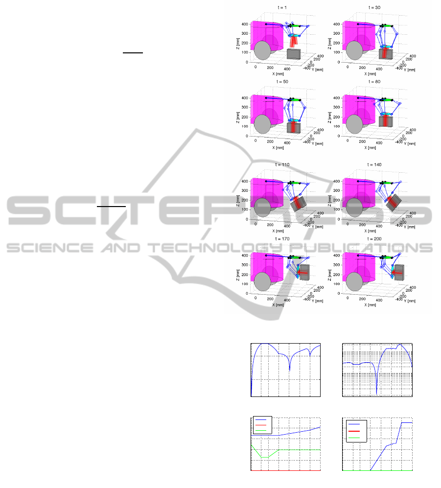
Figure 10: Forward handing motion.
1 30 50 80 110 140 170 200
10
15
10
20
n
θ
t
1 30 50 80 110 140 170 200
10
2
10
3
10
4
n
h
t
1 30 50 80 110 140 170 200
0
100
200
300
400
500
t
[mm]
hand position
x
y
z
1 30 50 80 110 140 170 200
0
20
40
60
80
100
t
[deg]
hand rotation
θ
x
θ
y
θ
z
Figure 11: Simulation results in forward handing motion.
move. It will be better than when the robot moves it-
self for stable handling. Based on this consideration,
a simple motion planning for a handling task was im-
plemented. The procedure is as follows:
1. If the hand is not in whole workable space by the
hand and swing motion, the robot moves to appro-
priate position and orientation.
2. If the hand is not in workable space by the hand
only, the hand moves to appropriate position by
DevelopmentofaParallelLinkArmforObjectHandlingbyWheeledMobileRobot
595
rotating swing link.
3. The hand-unit position p
hdest
and orientation
r
hdest
at the destination are obtained according to
the states of target object, where r
h
= (θ
x
, θ
y
, θ
z
)
T
.
4. From the hand-unit position p
h
(t) and orientation
r
h
(t) at current time t, desired states at the next
time p
h
(t + 1) and r
h
(t + 1) are computed. Con-
sidering a simple straight path, these are given by
p
h
(t + 1) = p
h
(t) +
p
hdest
− p
h
(t)
t
dest
and
r
h
(t + 1) = r
h
(t) +
r
hdest
− r
h
(t)
t
dest
where t
dest
is the time to destination from current
time.
5. The norms n
θ
and n
h
for p
h
(t + 1) and r
h
(t + 1)
are calculated by (7) and (8). Using thresholds v
θ
and v
h
, if both values meet n
θ
≥ v
θ
and n
h
≥ v
h
,
the hand moves to p
h
(t + 1) and r
h
(t + 1). Then,
time is updated and goes to 4 for the next time.
6. If n
θ
< v
θ
or n
h
< v
h
, the hand position or orienta-
tion is kept to be p
h
(t + 1) = p
h
(t) or r
h
(t + 1) =
r
h
(t) and repeat 5. If neither case satisfies n
θ
≥ v
θ
and n
h
≥ v
h
, we assume that the motion can not
be achieved in current hand state, so go back to 1.
4.2 Forward Handing Motion
Figure 10 shows an example of object handling mo-
tion in which the robot picks up an object and carries
it forward. The hand-unit position p
h
(t) and orienta-
tion r
h
(t) at each time step t were as described in Sec-
tion 4.1. The hand starts moving down to the object
at t = 1, starts closing at t = 30, and grasps the object
at t = 50. After that, the robot picks up the object and
starts rotating the hand to turn the object forward at
t = 80. Finally, the object is oriented horizontally at
t = 170, and moved forward slightly at t = 200.
Figure 11 shows transitions of norms n
θ
and n
h
,
hand-unit position p
h
(t), and hand rotation r
h
(t) to
the time step in this motion. To easily correspond to
the positions in Fig. 10, the values of hand position
are represented in the robot coordinate system Σ
Robot
.
We can see that θ
x
, the hand rotation angle around x
B
,
does not change linearly around t = 140. It is due to
a mechanical constraint caused by large angles of the
third joint of the front two link-units. After the hand
moves forward further, the rotation angles can change
linearly.
The robot can apply this hand motion to pick up a
target object and carry it to the destination with mov-
ing itself in wide area.
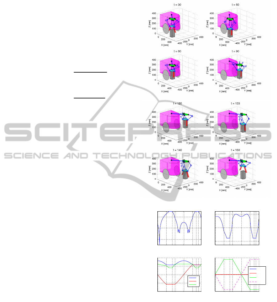
Figure 12: Pick and place motion from right to left side.
1 30 5060 90 120133140150
10
10
10
15
10
20
n
θ
t
1 30 5060 90 120133140150
10
3.1
10
3.3
10
3.5
n
h
t
1 30 5060 90 120133140150
−400
−200
0
200
400
t
[mm]
hand position
x
y
z
1 30 5060 90 120133140150
−50
0
50
t
[deg]
hand rotation
θ
x
θ
y
θ
z
θ
swing
Figure 13: Simulation results in pick and place motion.
4.3 Pick and Place from Side to Side
Figure 12 shows an example of motion in which the
robot picks an object at the right side, carries it to the
opposite side using the swing link, and places it. Af-
ter the swing link rotates to -45 degrees at t = 30, the
hand moves down and picks up the object at t = 60.
The swing link then starts rotating 90 degrees with
keeping orientation of the object at t = 120, and re-
leases the object at t = 140.
ICINCO2014-11thInternationalConferenceonInformaticsinControl,AutomationandRobotics
596
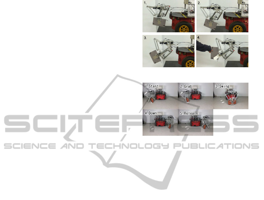
Figure 13 shows transitions of n
θ
, n
h
, p
h
(t), and
r
h
(t) to the time step in this motion. Each result was
obtained in the same way as previous motion. In this
case, the angle of swing link θ
swing
is changed linearly
to move the hand so that the destination comes in the
workable area of hand. The hand rotation angle θ
z
is
changed corresponding to the change of θ
swing
to keep
the orientation of the object.
5 EXPERIMENTS
5.1 Forward Handing Motion
Figure 14 shows an experiment for handing object.
The robot kept grasping a B4-size notebook (panel 1
in Fig. 14), started rotating the hand after slight down
(panel 2), carry the object forward (3), and handed it
by opening the hand (4). It was actually difficult to
rotate the hand forward so that the object orients hor-
izontally as shown in Fig. 10 due to some mechanical
constraints of the second and third joints of link-units.
Nevertheless, this result indicates the ability of hand-
ing task of the robot with parallel link arm.
5.2 Pick and Place from Side to Side
The robot carried an object from right to left with
swinging motion. Figure 15 shows a sequence of the
motion in this experiment. We used a 2.1 [kg] brick
as the target object, which was 100 [mm] in length,
200 [mm] in width, and 52 [mm] in height. The robot
moved the hand down at the right side (panel 1 in
Fig. 15), started grasping the object (panel 2). Af-
ter lifted it up slightly, the robot was swinging it the
parallel link arm to the left side (3). The robot finally
stopped swinging at the destination and touched the
object to the floor (4) and released it (5). This result
verified the validity of working area by utilizing the
swing link.
Although it was actually difficult to move hand
so as to keep its orientation as shown in Fig. 12 due
to some mechanical constraints, this kind of motion
shows that the robot has an ability of performing han-
dling tasks in small space, such as an arrangement of
books between book-shelves in library.
6 CONCLUSIONS
We have developed a parallel link arm to be mounted
on a wheeled mobile robot. Kinematic analysis and
Figure 14: Handing object forward.
Figure 15: Picking and placing from right to left side.
basic motions of the parallel link arm have been pre-
sented. Simulations and experiments confirmed ba-
sic handling motions of the arm even though it had
some mechanical constraints. More detailed kine-
matic analysis should be considered. In future, we
will confirm the potential of the robot by demonstrat-
ing variety of work in wide area as well as narrow
space with the advantage of parallel link by which it
can handle heavier object than serial link manipulator.
REFERENCES
Decker, M., Dang, A., and Ebert-Uphoff, I. (2001). Motion
planning for active acceleration compensation. In Pro-
ceedings of IEEE ICRA 2001, volume 2, pages 1257–
1264.
Gosselin, C. and Angeles, J. (1990). Singularity analysis of
closed-loop kinematic chains. IEEE Transactions on
Robotics and Automation, 6(3):281–290.
Graf, R. and Dillmann, R. (1997). Active Acceleration
Compensation Using a Stewart-Platform on a Mobile
Robot 2 The mobile robots 1 Introduction. In 2nd Eu-
romicro Workshop on Advanced Mobile Robots, pages
59–64.
Horin, P., Djerassi, S., Shoham, M., and Horin, R. (2006).
Dynamics of a six degrees-of-freedom parallel robot
actuated by three two-wheel carts. Multibody System
Dynamics, 16(2):105–121.
Li, Y., Xu, Q., and Liu, Y. (2006). Novel design and model-
ing of a mobile parallel manipulator. In Proceedings
of IEEE ICRA 2006, pages 1135–1140.
Pierrot, F., Uchiyama, M., Dauchez, P., and Fournier, A.
DevelopmentofaParallelLinkArmforObjectHandlingbyWheeledMobileRobot
597

(1990). A new design of a 6-DOF parallel robot. Jour-
nal of Robotics and Mechatronics, 2(4):308–315.
Shoval, S. and Shoham, M. (2001). Sensory redundant
parallel mobile mechanism. In Proceedings of IEEE
ICRA 2001, volume 3, pages 2273–2278.
Yamawaki, T., Omata, T., and Mori, O. (2004). 4r and 5r
parallel mechanism mobile robots. In Proceedings of
IEEE ICRA 2004, volume 4, pages 3684–3689.
ICINCO2014-11thInternationalConferenceonInformaticsinControl,AutomationandRobotics
598
