
Low-cost EM-Simulation-based Multi-objective Design Optimization
of Miniaturized Microwave Structures
Slawomir Koziel
1
, Adrian Bekasiewicz
2
, Piotr Kurgan
2
and Leifur Leifsson
1
1
Engineering Optimization & Modeling Center, Reykjavik University, Menntavegur 1, 101 Reykjavik, Iceland
2
Faculty of Electronics, Telecommunications and Informatics, Gdansk University of Technology, 80-233 Gdansk, Poland
Keywords: Miniaturized Microwave Structures, Design Optimization, Multi-Objective Optimization, Simulation-
Driven Design, Surrogate-based Optimization, Space Mapping.
Abstract: In this work, a simple yet reliable technique for fast multi-objective design optimization of miniaturized
microwave structures is discussed. The proposed methodology is based on point-by-point identification of a
Pareto-optimal set of designs representing the best possible trade-offs between conflicting objectives such as
electrical performance parameters as well as the size of the structure of interest. For the sake of
computational efficiency, most operations are performed on suitably corrected equivalent circuit model of
the structure under design. Model correction is implemented using a space mapping technique involving,
among others, frequency scaling. Our approach is demonstrated using a compact rat-race coupler. For this
specific example, a set of ten designs representing a Pareto set for two objectives (electrical performance
and the layout area) is identified at the cost corresponding to less than thirty high-fidelity EM simulations of
the structure.
1 INTRODUCTION
Design of miniaturized microwave structures for
contemporary wireless communication systems is a
challenging task. It involves, among others,
adjustment of designable (usually geometry)
parameters of the structure to satisfy multiple, often
conflicting objectives such as size, bandwidth, phase
response, etc. (Yeung and Man, 2011). Important
characteristics of compact structures, e.g., folded or
fractal-shaped couplers (Tseng and Chen, 2008;
Ghali and Moselhy, 2008; Liao, et al., 2005), are
densely packed layouts. Due to considerable
electromagnetic couplings between various parts of
such circuits, high-fidelity electromagnetic (EM)
analysis is the only way of accurate evaluation of
their electrical performance parameters.
Unfortunately, high-fidelity EM simulation is
computationally expensive, which turns out to be a
fundamental issue in simulated-driven design of
compact components. Conventional design strategies
such as repetitive parameter sweeps guided by
engineering experience or direct EM-driven
optimization—using, e.g., gradient-based or
derivative free methods (Nocedal and Wright, 2006;
Rios and Sahinidis, 2013)—require large number of
EM analyses, the total cost of which may be
unacceptable from practical point of view or even
prohibitive. On the other hand, alternative
techniques for performance evaluation (e.g.,
exploiting transmission line theory) are grossly
inaccurate. This is particularly true for highly
miniaturized circuits with coupled building blocks
(e.g. Bekasiewicz and Kurgan, 2014; Wincza and
Gruszczynski, 2013; Kurgan and Bekasiewicz, 2014;
Tsai, 2013; Koziel, et al., 2014).
These difficulties can be alleviated, to some
extent, by means of surrogate-based optimization
(SBO) techniques such as space mapping (SM),
which have proven their computational superiority
over traditional optimization algorithms applied to
the design of conventional microwave circuits. SBO
schemes benefit from low-cost surrogates that are
aligned with high-fidelity EM models through
adaptive corrections (Bandler et al., 2004b; Koziel et
al., 2006; Koziel et al., 2008). Because most of
operations are carried out on the corrected low-
fidelity model, and the high-fidelity EM simulation
is only launched occasionally (to verify the current
design and update the surrogate model), the overall
cost of the SBO process can be kept low.
As opposed to conventional designs, compact
767
Koziel S., Bekasiewicz A., Kurgan P. and Leifsson L..
Low-cost EM-Simulation-based Multi-objective Design Optimization of Miniaturized Microwave Structures.
DOI: 10.5220/0005127107670774
In Proceedings of the 4th International Conference on Simulation and Modeling Methodologies, Technologies and Applications (SDDOM-2014), pages
767-774
ISBN: 978-989-758-038-3
Copyright
c
2014 SCITEPRESS (Science and Technology Publications, Lda.)

structures are typically developed based on novel
topologies and the influence of the structure size on
its performance capabilities cannot be foreseen
beforehand (Kurgan et al., 2012; Bekasiewicz et al.,
2012). To eliminate the risk of design failure in the
case of excessively stringent specifications that
cannot be met by a prototype circuit, multi-objective
optimization becomes a necessity. The goal here,
rather than a single optimum design, is to find the
entire set of designs (a so-called Pareto set)
representing the best possible trade-offs between
non-commensurable objectives. The most popular
solution approach is population-based metaheuristics
(Afshinmanesh et al., 2008; Deb, 2001; Jin and
Rahmat-Samii, 2010; Koulouridis et al., 2007;
Koziel and Ogurtsov, 2013; Yeung and Man, 2011).
While methods such as genetic algorithms or particle
swarm optimizers are capable of identifying the
entire Pareto set in one algorithm run, these methods
are of limited use for compact circuit design due to a
large number (from hundreds to tens of thousands)
of objective function evaluations involved (Koziel et
al., 2014; Koziel and Ogurtsov, 2013).
In this paper, we propose a computationally
efficient procedure for multi-objective simulation-
driven design of compact microwave passives. Our
methodology exploits surrogate-based optimization,
an equivalent circuit representation of the structure,
and space mapping correction techniques to perform
a point-by-point Pareto set identification. Our
approach is illustrated using a compact rat-race
coupler design.
2 CASE STUDY: COMPACT
RAT-RACE COUPLER
In this section, we provide a description of a specific
miniaturized microwave circuit to be used for
explaining and demonstrating the proposed multi-
objective design optimization methodology. We also
describe the design objectives that will be of interest.
2.1 Compact Rat-Race Coupler
Consider a novel structure of an equal-split
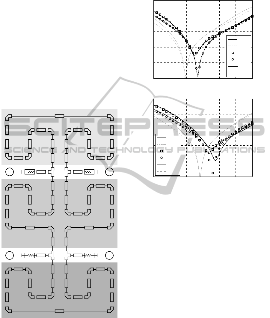
miniaturized rat-race coupler (RRC) shown in Fig. 1.
Figure 1: Geometry of a considered compact rat-race
coupler.
The structure miniaturization is achieved by folding
each 70.7 Ω section. The considered RRC is
designed on Taconic RF-35 substrate (ε
r
= 3.5, h =
0.762 mm, tanδ = 0.018). The input impedance is 50
Ω. The vector of coupler dimensions is: x = [l
1
l
2
l
3
d
w]
T
, whereas w
0
= 1.7, l
0
= 15 remain fixed (all
dimensions in mm). The low- and high-fidelity
models of the structure are prepared with Agilent
ADS (Agilent ADS, 2011) and CST Microwave
Studio (CST, 2013) (~220,000 mesh cells and
simulation time ~15 minutes per design),
respectively. Lower/upper bounds l/u of the solution
space are represented by the following vectors: l = [2
10 17 0.2 0.5]
T
and u = [8 16 25 1.2 1.5]
T
. The initial
design is: x = [5 14 21 07 0.9]
T
.
2.2 Design Objectives
There are two objectives considered in the coupler
design: F
1
– maximization of bandwidth (defined as
intersection of |S
11
| and |S
41
| below –20 dB) centred
around the operating frequency of 1 GHz, and F
2
–
minimization of the RRC footprint (layout area).
1
2
3
4
l
0
w
0
d
l
1
l
2
w
l
3
SIMULTECH2014-4thInternationalConferenceonSimulationandModelingMethodologies,Technologiesand
Applications
768

These two objectives are generally conflicting,
which means that reducing the layout area results in
reduction of the –20 dB bandwidth. The purpose of
multi-objective design in this case it to find out
possible trade-offs between the objectives.
Knowledge about these trade-offs is of fundamental
importance for the designer, especially when
selecting a structure for a particular application.
3 MULTI-OBJECTIVE DESIGN
METHODOLOGY
In this section, we formulate the multi-objective
design problem, discuss surrogate modelling using
space mapping, as well as describe the proposed
multi-objective optimization approach. The
numerical results obtained for the example structure
of Section 2 are presented in Section 4.
3.1 Multi-Objective Design Problem
Formulation
Let F
k
(R
f
(x)), where k = 1, …, N
obj
, be a kth design
objective. Typical objectives include electrical
performance parameters as well as the component
size (in particular the area occupied by the circuit
layout), the latter being critical for the design of
compact structures. In multi-objective scheme we
seek for a representation of a so-called Pareto-
optimal set X
P
, which is composed of non-dominated
designs such that for any x X
P
, there is no other
design y for which the relation y x is satisfied (y
x, i.e., y dominates over x, if F
k
(R
f
(y)) F
k
(R
f
(x)) for
all k = 1, …, N
obj
, and F
k
(R
f
(y)) < F
k
(R
f
(x)) for at
least one k) (Deb, 2001).
3.2 Low-Fidelity Model. Surrogate
Modelling using Space Mapping
The most popular solution approaches for multi-
objective problems are undoubtedly population-
based metaheuristics (Venkatarayalu et al., 2005;
Guimaraes et al., 2006; Yang et al., 2008), including
genetic algorithms (Kuwahara, 2005) or particle
swarm optimizers (Jin and Rahmat-Samii, 2007).
The most important advantage of these techniques is
their ability to identify the entire Pareto set in a
single algorithm run. Unfortunately, the
computational cost of metaheuristic algorithms is
normally very high – typically, thousands or tens of
thousands of objective function evaluations
(Afshinmanesh et al., 2008; Chamaani et al., 2011;
Kuwahara, 2005). Consequently, metaheuristics are
only suitable for handling problems where
computational cost of objective evaluation is not of a
major concern. Here, EM-simulated high-fidelity
model is too expensive to be directly handled in a
multi-objective optimization setting. Therefore, we
use an auxiliary equivalent circuit (low-fidelity)
model R
c
, evaluated by means of a circuit simulator
(Bandler et al., 2001; Koziel et al., 2008; Bandler et
al., 2002), here, Agilent ADS (Agilent ADS, 2011).
Figure 2 shows the circuit model for the coupler
structure of Fig. 1.
The low-fidelity model is very fast, however, it is
not an accurate representation of R
f
. Its corrected
version, a surrogate model R
s
, will be utilized in the
optimization process (Bandler et al., 2004a; Cheng
et al., 2004). Based on initial inspection of the type
of misalignment between the low- and high-fidelity
models, implicit and frequency space mapping (SM)
seem to be the most suitable correction techniques.
More specifically, the surrogate model is defined as
.
() (; , )
R
xRxfp
scF
(1)
where R
c.F
is a frequency-scaled low-fidelity model,
whereas f and p are frequency SM and implicit SM
parameters, respectively.
Let R
c
(x) = [R
c
(x,
1
) R
c
(x,
2
) … R
c
(x,
m
)]
T
,
where R
c
(x,
j
) is evaluation of the circuit model at a
frequency
j
. Then, R
c.F
(x;f,p) = [R
c
(x,f
0
+
1
f
1
,p) … R
c
(x, f
0
+
m
f
1
,p)]
T
, with f
0
and f
1
being
frequency scaling parameters. Here, implicit SM
parameters p are dielectric permittivity as well as
thickness of the microstrip components of the circuit
corresponding to selected groups of components as
indicated in Fig. 2. SM parameters are extracted to
minimize misalignment between R
s
and R
f
as
follows:
**
.
,
[,]argmin|| () (;,)||
fp
fp Rx R xfp
fcF
(2)
Figure 3 shows the responses of the high- and
low-fidelity model at certain design x, as well as the
response of the surrogate model R
s
at the same
design. It can be observed that the model alignment
is greatly improved, however, generalization
capability of the surrogate is limited (cf. Fig. 3(b)).
In particular, it is not possible to find a single set of
SM parameters that would ensure surrogate model
accuracy across the entire design space. As a
consequence, in order to lead towards a satisfactory
design, the surrogate has to be iteratively refined
during the optimization process.
Low-costEM-Simulation-basedMulti-objectiveDesignOptimizationofMiniaturizedMicrowaveStructures
769
3.3 Optimization Algorithm
Due to the limited generalization capability of the
SM surrogate model mentioned in Section 3.2, as
well as required reduction of the computational cost
of the multi-objective optimization process, our
design approach is based on point-by-point
identification of the Pareto set. In the first step, the
coupler structure is optimized taking into account
the first objective only (here, electrical parameters).
The obtained value F
1
(R
f
(x
p
(1)
)) at the optimum
design x
p
(1)
determines, together with the
corresponding value of the second objective (here,
layout area), F
2
(1)
= F
2
(R
f
(x
p
(1)
)), the extreme points
of the Pareto set.
Figure 2: Equivalent circuit model of the coupler structure
of Fig. 1 with highlighted regions with different implicit
SM parameters p (model implemented in Agilent ADS).
(a)
(b)
Figure 3: Responses of the high- and low-fidelity coupler
models as well as the SM surrogate (a) at certain design x
(at which the surrogate is extracted), and (b) at some other
design. Plot (b) indicates limited generalization capability
of the surrogate.
In the subsequent steps, we set the threshold
values for the second objective F
2
(j)
, and optimize
the structure with respect to the first objective so that
the above threshold value is preserved:
()
2
2
()
1
,( ())
arg min ( )
xRx
xRx
j
f
j
pf
FF
F
(3)
Here, x
p
(j)
is the jth element of the Pareto set. The
process is continued until F
1
(R
f
(x
p
(j)
)) is still
satisfactory from the point of view is given design
specifications.
Problem (3) is solved using the SM surrogate
model (cf. Section 2.2) and it is itself realized as an
iterative process
()
(.)
2
2
(.) (.)
1
,( ())
arg min ( )
xR x
xRx
j
jk
s
jk jk
ps
FF
F
(4)
ε
11
,
h
ε
22
,
h
ε
33
,
h
1
2
3
4
0.7 0.8 0.9 1 1.1 1.2 1.3
-50
-40
-30
-20
-10
0
Frequency [GHz]
S-parameters [dB]
|
S
11
|
R
f
|
S
41
|
R
f
|
S
11
|
R
s
|
S
41
|
R
s
|
S
11
|
R
c
|
S
41
|
R
c
0.7 0.8 0.9 1 1.1 1.2 1.3
-50
-40
-30
-20
-10
0
Frequency [GHz]
S-parameters [dB]
|
S
11
|
R
f
|
S
41
|
R
f
|
S
11
|
R
s
|
S
41
|
R
s
|
S
11
|
R
c
|
S
41
|
R
c
SIMULTECH2014-4thInternationalConferenceonSimulationandModelingMethodologies,Technologiesand
Applications
770
where
(.) (.) (.)
.
() (; , )RxRxf p
j
kjkjk
scF
(5)
and
(.) (.)
(.) (.)
.
,
[,]
arg min || ( ) ( ; , ) ||
fp
fp
R
xRx
f
p
jk jk
jk jk
fcF
(6)
The starting point for the algorithm (4) is x
p
(j–1)
(the previously obtained Pareto set point). Normally,
two iterations of (4) are sufficient to obtain x
p
(j)
,
which is because the starting point is already a good
approximation of the optimum. In practice, the
thresholds F
2
(j)
can be obtained as F
2
(j)
=
F
2
(j–1)
with
< 1 (e.g.,
= 0.95), or F
2
(j)
= F
2
(j–1)
–
with
> 0 (e.g.,
= 0.05
F
2
(1)
).
The computational cost of the entire multi-
objective design process using the proposed
methodology can be estimated (in terms of the
number of EM simulations of the structure) as NK,
where N is the number of point in the Pareto set, and
K is the average number of iterations (4) necessary
to obtain the next point. In practice, K 3.
It should also be mentioned that another
important design goal, i.e., |S
21
| = |S
31
| at the
operating frequency (here, 1 GHz), ensuring equal
division of the signal power between ports 2 and 3
of the circuit, is handled implicitly. More
specifically, it is enforced for each design obtained
in the optimization process by applying an additional
penalty function to F
1
in (4) that penalizes designs
for which | |S
21
| – |S
31
| | > ds at the operating
frequency (here, we use ds = 0.1 dB, as an
acceptable inaccuracy level).
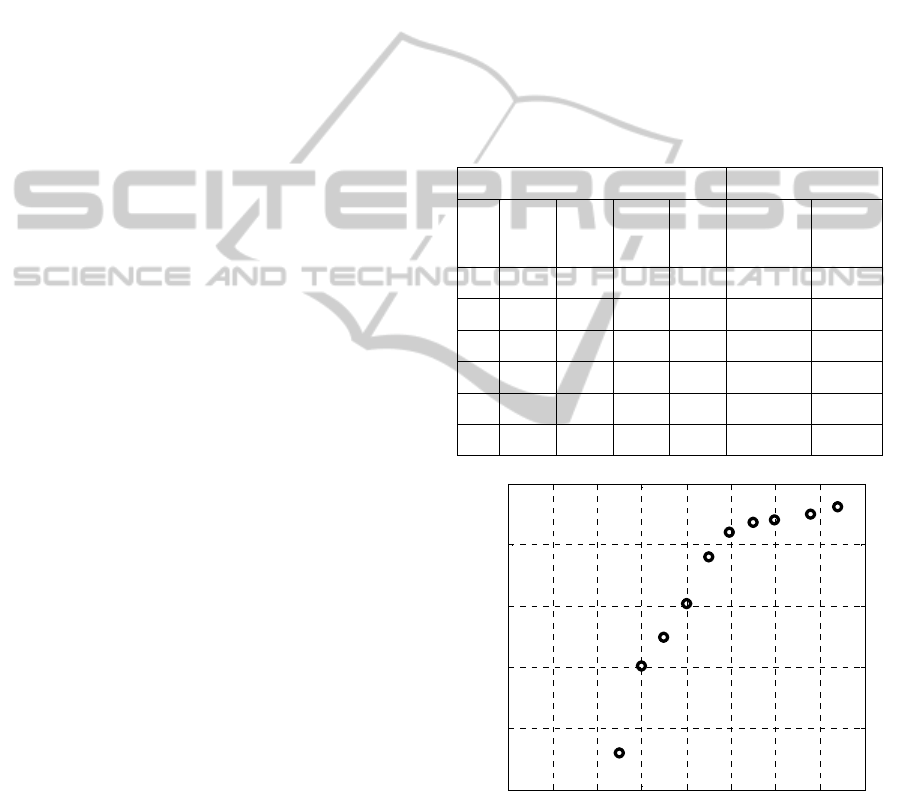
4 NUMERICAL RESULTS
The coupler structure of Section 2 has been designed
using the multi-objective design methodology
described in Section 3. The first design obtained by
using (4) without any area constraints resulted in
-20 dB bandwidth of 281 MHz and the layout area
of 570 mm
2
. Nine other designs have been obtained
by setting up F
2
(j)
to 540, 500, 475, 450, 425, 400,
375, 350, and 325 mm
2
, respectively. Figure 4
shows the obtained representation of the Pareto
front.
For the layout area of 300 mm
2
, it was
impossible to obtain a design with positive value of
–20 dB bandwidth, which essentially means that 300
mm
2
is a lower limit (in terms of layout area) for
practically useful designs for this particular coupler
topology. This is—from the designer standpoint—an
important information regarding miniaturization
limitations, which may be utilized, e.g., to
discriminate structures suitable for a given (in
particular, space-limited) application.
Table 1 and Figure 5 show the numerical data
and frequency characteristics for the selected
designs. It can be observed that the coupler size can
be reduced by over 40 percent with respect to its
original size (corresponding to the best possible
electrical performance), while maintaining
acceptable performance.
Table 1: Multi-objective design optimization of rat-race
coupler: selected results.
Design Variables [mm] Objectives
l
1
l
2
l
3
d W
–20 dB
Bandwidth
[MHz]
Layout
Area
[mm
2
]
4.18 13.20 20.68 0.994 0.865 281 570
3.83 11.76 20.44 0.825 0.877 270 500
4.10 13.78 21.14 0.581 0.887 260 450
4.25 12.17 22.12 0.400 0.923 202 400
3.95 10.87 21.71 0.350 0.936 174 375
4.37 12.33 22.52 0.350 0.820 151 350
Figure 4: Pareto set obtained using the proposed multi-
objective design optimization methodology.
Both Figure 4 and Table 1 indicate the
conflicting nature of the considered objectives:
reduction of the layout area of the circuit inevitably
results in degrading its electrical performance, here,
–20 dB bandwidth.
200 250 300 350 400 450 500 550 600
50
100
150
200
250
300
Coupler layout area [mm
2
]
-20 dB bandwidth [MHz]
Low-costEM-Simulation-basedMulti-objectiveDesignOptimizationofMiniaturizedMicrowaveStructures
771
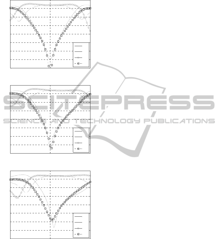
(a)
(b)
(c)
Figure 5: Frequency characteristics for selected coupler
designs, corresponding to the layout area 570 mm
2
(a),
448 mm
2
(b), and 375 mm
2
(c).
All the designs along the Pareto front are
nominally satisfying the basic design goal (i.e., both
|S
11
| and |S
41
| are lower than –20 dB and centred
around the operating frequency of 1 GHz). However,
the designs with wider –20 dB bandwidth (such as
the one shown in Fig. 5(a) versus that in Fig. 5(c))
are electrically better because of higher chance of
satisfying design specifications in case of
unavoidable manufacturing tolerances (a
consequence of which will be a deviation of actual
characteristics of the fabricated circuit with respect
to the nominal ones).
The total cost of the design process corresponds
to less than 30 high-fidelity model evaluations (~7.5
hours), including the overhead related to multiple
evaluations of the circuit model R
c
(the latter does
not exceed 20 percent of the overall EM simulation
cost). It should be noted that direct multi-objective
optimization of the high-fidelity EM antenna
model R
f
would not be possible (the expected cost of
a few thousand of model evaluations is practically
prohibitive).
5 CONCLUSIONS
In this paper, a technique for low-cost multi-
objective design optimization of miniaturized
microwave structures has been proposed. The design
speedup has been obtained through the usage of
appropriately corrected, fast equivalent circuit model
of the structure under design. Another important
component was point-by-point Pareto set
identification through constrained single-objective
optimizations. As a result, the number of high-
fidelity EM simulations of the structure was greatly
reduced (to less than three per identified Pareto set
point). As demonstrated using a compact RRC
coupler, a set of designs corresponding to best
possible trade-offs between conflicting objectives
(here, electrical performance and the layout area of
the structure) has been obtained at a low
computational cost, corresponding to less than thirty
EM simulations of the coupler. According to our
knowledge, this is a first successful attempt to solve
the low-cost multi-objective design problem of
compact structures exploiting surrogate-based
optimization.
The future work will aim at extending the
presented methodology to cases with larger number
of conflicting design objectives, as well as applying
it to other classes of structures, especially antennas,
where fast equivalent circuit models are normally
unavailable.
0.5 1 1.5
-40
-35
-30
-25
-20
-15
-10
-5
0
Frequency [GHz]
S-parameters [dB]
|
S
11
|
|
S
21
|
|
S
31
|
|
S
41
|
0.5 1 1.5
-40
-35
-30
-25
-20
-15
-10
-5
0
Frequency [GHz]
S-parameters [dB]
|
S
11
|
|
S
21
|
|
S
31
|
|
S
41
|
0.5 1 1.5
-40
-35
-30
-25
-20
-15
-10
-5
0
Frequency [GHz]
S-parameters [dB]
|
S
11
|
|
S
21
|
|
S
31
|
|
S
41
|
SIMULTECH2014-4thInternationalConferenceonSimulationandModelingMethodologies,Technologiesand
Applications
772

ACKNOWLEDGEMENTS
The authors thank Computer Simulation Technology
AG, Darmstadt, Germany, for making CST
Microwave Studio available. This work was
supported in part by the Icelandic Centre for Research
(RANNIS) Grant 13045051.
REFERENCES
Afshinmanesh, F., Marandi, A., Shahabadi, M. 2008.
Design of a Single-Feed Dual-Band Dual-Polarized
Printed Microstrip Antenna Using a Boolean Particle
Swarm Optimization. In IEEE Transactions on
Antennas and Propagation, 56, 1845—1852.
Agilent ADS 2011. Agilent Technologies, 1400
Fountaingrove Parkway, Santa Rosa, CA 95403-1799,
USA.
Bandler, J.W., Georgieva, N., Ismail, M.A., Rayas-
Sanchez, J.E., Zhang, Q.-J. 2001. A generalized space-
mapping tableau approach to device modeling. In
IEEE Transactions on Microwave Theory and
Techniques, 49, 67—79.
Bandler, J.W., Ismail, M.A., Rayas-Sanchez, J.E. 2002.
Expanded space-mapping EM-based design
framework exploiting preassigned parameters. In IEEE
Transactions on Circuits and Systems I: Fundamental
Theory and Applications, 49, 1833—1838.
Bandler, J.W., Cheng, Q.S. Hailu, D.M., Nikolova, N.K.
2004. A space-mapping design framework. In IEEE
Transactions on Microwave Theory and Techniques,
52, 2601—2610.
Bandler, J.W., Cheng, Q.S., Dakroury, S.A., Mohamed,
A.S., Bakr, M.H., Madsen, K., Søndergaard, J. 2004.
Space mapping: the state of the art. In IEEE
Transactions on Microwave Theory and Techniques,
52, 337—361.
Bekasiewicz, A., Kurgan, P., Kitlinski, M. 2012. New
approach to a fast and accurate design of microwave
circuits with complex topologies. In IET Microwaves,
Antennas & Propagation, 6, 1616—1622.
Bekasiewicz, A., Kurgan, P. 2014. A compact microstrip
rat-race coupler constituted by nonuniform
transmission lines. In Microwave and Optical
Technology Letters, 56, 970—974.
Chamaani, S., Mirtaheri, S.A., Abrishamian, M.S. 2011.
Improvement of Time and Frequency Domain
Performance of Antipodal Vivaldi Antenna Using
Multi-Objective Particle Swarm Optimization. In
IEEE Transactions on Antennas and Propagation, 59,
1738—1742.
Cheng, Q.S., Bandler, J.W., Koziel, S. 2010. Space
Mapping Design Framework Exploiting Tuning
Elements. In IEEE Transactions on Microwave Theory
and Techniques, 58, 136—144.
CST Microwave Studio 2013. Computer Simulation
Technology AG, Bad Nauheimer Str. 19, D-64289
Darmstadt, Germany.
Deb., K. 2001. Multi-Objective Optimization Using
Evolutionary Algorithms. John Wiley & Sons. New
York.
Ghali, H., Moselhy, T.A. 2004. Miniaturized Fractal Rat-
Race, Branch-Line, and Coupled-Line Hybrids. In
IEEE Transactions on Microwave Theory and
Techniques, 52, 2513—2520.
Guimaraes, F.G., Lowther, D.A., Ramirez, J.A. 2006.
Multiobjective approaches for robust electromagnetic
design. In IEEE Transactions on Magnetics, 42,
1207—1210.
Jin, N. Rahmat-Samii, Y., 2007. Advances in Particle
Swarm Optimization for Antenna Designs: Real-
Number, Binary, Single-Objective and Multiobjective
Implementations. In
IEEE Transactions on Antennas
and Propagation, 55, 556—567.
Jin, N., Rahmat-Samii, Y. 2010. Hybrid Real-Binary
Particle Swarm Optimization (HPSO) in Engineering
Electromagnetics. In IEEE Transactions on Antennas
and Propagation, 58, 3786—3794.
Koulouridis, S., Psychoudakis, D., Volakis, J. 2007.
Multiobjective Optimal Antenna Design Based on
Volumetric Material Optimization. In IEEE
Transactions on Antennas and Propagation, 55, 594—
603.
Koziel, S., Bandler, J.W., Madsen, K. 2006. A space
mapping framework for engineering optimization:
theory and implementation. In IEEE Transactions on
Microwave Theory and Techniques, 54, 3721—3730.
Koziel, S., Bandler, J.W., Madsen, K. 2008. Quality
assessment of coarse models and surrogates for space
mapping optimization. In Optimization and
Engineering, 9, 375—391.
Koziel, S., Cheng, Q.S., Bandler, J.W. 2008. Space
mapping. In IEEE Microwave Magazine, 9, 105—122.
Koziel, S., Ogurtsov, S. 2013. Multi-Objective Design of
Antennas Using Variable-Fidelity Simulations and
Surrogate Models. In IEEE Transactions on Antennas
and Propagation, 61, 5931—5939.
Koziel, S., Bekasiewicz, A., Kurgan, P. 2014. Rapid EM-
driven Design of Compact RF Circuits By Means of
Nested Space Mapping. In IEEE Microwave and
Wireless Components Letters, 24, 364—366.
Koziel, S., Bekasiewicz, A., Zieniutycz, W. 2014.
Expedite EM-Driven Multi-Objective Antenna Design
in Highly-Dimensional Parameter Spaces. In IEEE
Antennas and Wireless Propagation Letters, 13, 631—
634.
Kurgan, P., Filipcewicz, J., Kitlinski, M. 2012.
Development of a compact microstrip resonant cell
aimed at efficient microwave component size
reduction. In IET Microwaves, Antennas &
Propagation, 6, 1291—1298.
Kurgan, P., Bekasiewicz, A. 2014. A robust design of a
numerically demanding compact rat-race coupler. In
Microwave and Optical Technology Letters, 56,
1259—1263.
Low-costEM-Simulation-basedMulti-objectiveDesignOptimizationofMiniaturizedMicrowaveStructures
773

Kuwahara, Y. 2005. Multiobjective optimization design of
Yagi-Uda antenna. In IEEE Transactions on Antennas
and Propagation, 53, 1984—1992.
Liao, S.-S., Sun, P.-T., Chin, N.-C., Peng, J.-T. 2005. A
novel compact-size branch-line coupler. In IEEE
Microwave and Wireless Components Letters, 15,
588—590.
Nocedal, J., Wright, S. 2006. Numerical optimization,
Springer, 2
nd
edition.
Rios, L.M., Sahinidis, N.V. 2013. Derivative-free
optimization: a review of algorithms and comparison
of software implementations. In Journal of Global
Optimization, 56, 1247—1293.
Tsai, L.-T. 2013. A compact dual-passband filter using
stepped-impedance resonators. In Microwave and
Optical Technology Letters, 55, 2514—2517.
Tseng, C.-H., Chen, H.-J. 2008. Compact Rat-Race
Coupler Using Shunt-Stub-Based Artificial
Transmission Lines. In IEEE Microwave and Wireless
Components Letters, 18, 734—736.
Venkatarayalu, N.V., Ray, T., Gan, Y.-B. 2005. Multilayer
dielectric filter design using a multiobjective
evolutionary algorithm. In IEEE Transactions on
Antennas and Propagation, 53, 3625—3632.
Wincza, K., Gruszczynski, S. 2013. Theoretical limits on
miniaturization of directional couplers designed as a
connection of tightly coupled and uncoupled lines. In
Microwave and Optical Technology Letters, 55, 223—
230.
Yang, X.-S., Ng, K.-T., Yeung, S.H., Man, K.F. 2008.
Jumping Genes Multiobjective Optimization Scheme
for Planar Monopole Ultrawideband Antenna. In IEEE
Transactions on Antennas and Propagation, 56,
3659—3666.
Yeung, S.H., Man, K.F. 2011. Multiobjective
Optimization. In IEEE Microwave Magazine, 12,
120—133.
SIMULTECH2014-4thInternationalConferenceonSimulationandModelingMethodologies,Technologiesand
Applications
774
