
Uncertainty Quantification in Smart Grid Co-simulation Across
Heterogeneous Model Domains
Cornelius Steinbrink
OFFIS – Institute for Information Technology, Escherweg 2, 26121 Oldenburg, Germany
1 MOTIVATION
The international power distribution grids are ex-
pected to undergo fundamental restructuring in the
next decades, becoming Smart Grids. Smart Grids are
typically defined as power grids enhanced with infor-
mation and communication technology (ICT). They
provide components of the power system with means
to send and receive information about current states,
energy requirements, load and generation predictions
etc. This calls for the development of various new
hardware devices and control concepts and thereby
for rigorous, systematic testing of the interaction be-
tween the new components.
Smart Grids are highly complex systems since
their dynamics do not solely depend on classical grid
components like generators and consumers anymore,
but also on weather predictions, market prices, the uti-
lization of the ICT system, and many other factors.
This complexity limits the pool of possible testing
procedures. Hardware experiments are too expensive
and inflexible to serve as generally applicable means
of testing. In the form of field tests they are even
potentially dangerous since real infrastructure is in-
volved. Software simulation is considered to be more
suitable for the early stages of Smart Grid research
since it is generally cheap, flexible and safe. However,
monolithic simulation software easily expires in its
usability since it does not consider the expendability
of the Smart Grid setup. Whenever new Smart Grid
components or concepts are introduced, they have to
be modeled and implemented by the software devel-
opers, which requires high manual effort and some-
times simply is not possible. In order to avoid this
overhead, the OFFIS – Institute for Information Tech-
nology, has developed the modular Smart Grid simu-
lation tool mosaik (Rohjans et al., 2013).
Mosaik is an event-based co-simulation frame-
work that allows the integration of existing Smart
Grid component models with the help of a flexible
API. The implemented models exchange data with
one another via mosaik and may be instantiated and
orchestrated to form large-scale simulation scenarios
(i.e. scenarios with thousands of model instances).
The extensive scenario size is enabled at reasonable
computational costs by employing steady-state calcu-
lation of the grid utilization in the frequency domain
(e.g. PyPower, a port of the MATPOWER package
(Zimmerman et al., 2011)). This means that short-
term dynamic behavior like electro-magnetic tran-
sients is not resolved.
Due to its flexible design, mosaik supports various
kinds of simulation processes, e.g. hardware emula-
tion. This is the concept of the Smart Energy Simula-
tion and Automation Laboratory (SESA-Lab) that has
been set up at the OFFIS. The central component of
the laboratory is the real-time simulator eMEGAsim
developed by the company OPAL-RT. This high per-
formance computer allows the simulation of network
models with µs resolution and provides digital and
analogue I/O capabilities that make it a ready-to-use
hardware-in-the-loop framework (HIL, see (de Jong
et al., 2011)). By combining mosaik and eMEGAsim,
the SESA-Lab enables analysis of dynamic transients
in precise subsystems of otherwise steady-state large-
scale scenarios. The main challenge of this approach
is to ensure accuracy of results for this heterogeneous
co-simulation system. A schematic overview of the
SESA-Lab setup is given in Figure 1.
2 STAGE OF THE RESEARCH
A showcase scenario has been implemented to
demonstrate the technical coupling between mosaik
and eMEGAsim. The scenario’s simulator pool con-
tains 44 low voltage grid nodes, 41 households, and
21 photovoltaic converters. The majority of these in-
stances is managed by mosaik. The included simula-
tors are based on time series and thus ensure power
generation and consumption within unproblematic
operational conditions. Similarly, no faults or power
outages have been modeled. Due to the simplicity of
this showcase it is a suitable starting point to system-
atically study the requirements for accurate coupling
16
Steinbrink C..
Uncertainty Quantification in Smart Grid Co-simulation Across Heterogeneous Model Domains.
Copyright
c
2014 SCITEPRESS (Science and Technology Publications, Lda.)
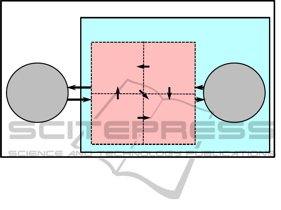
Transformation
of Continuous
Data
Latency
Handling
Dynamic
Scheduling
Uncertainty
Quantification
Coupling
SESA-Lab
eMEGAsim
dynamic
mosaik
Simulator
Pool
steady-state
(e.g. PyPower)
Figure 1: Schematic sketch of the SESA-Lab concept.
between the two systems.
A theoretical list of these requirements has already
been set up and is presented in Section 3. The require-
ment, on which this PhD project is focused, is un-
certainty quantification (UQ). It is the common way
to assess accuracy of measurements or simulation re-
sults. The challenges of designing a flexible UQ sys-
tem in the Smart Grid context are discussed in Sec-
tion 4. A systematic design approach has been de-
veloped to tackle these challenges. The approach is
outlined in Section 6.
3 OUTLINE OF OBJECTIVES
The main objective of the presented PhD project is the
improvement of the coupling between eMEGAsim
and mosaik. Since the former represents a highly dy-
namic time domain system while the latter represents
a steady-state frequency domain system, information
is inevitably lost, which leads to uncertainty in the
results. Four requirements have been identified that
need to be fulfilled in order to reduce this uncertainty
as much as possible and provide a measure for the re-
sult accuracy: information transfer, latency handling,
dynamic scheduling, and, as mentioned before, uncer-
tainty quantification.
The challenge of information transfer focuses on
the transformation of data. As already mentioned,
eMEGAsim calculates data in the time domain. Thus,
frequency domain transformation has to be performed
before sending data to mosaik. The simplest way
to do this is by calculating effective values of volt-
age and current, or via Fourier transform. However,
more elaborate techniques exist that support the goal
of preserving as much information as possible. No-
table concepts applied to power system analysis are
wavelet analysis (Shariatinasab et al., 2012), machine
learning (Wehenkel, 1997), and parameter estimation
(Lechtenberg et al., 2012). Choosing the most appro-
priate method or combination of methods for infor-
mation preservation is only one part of successful in-
formation transfer. It also has to be determined, in
which way mosaik (or implemented models) can ef-
fectively use this information. E.g. currently, there
is no component implemented in mosaik that is able
to process information about higher harmonics in the
eMEGAsim simulation. However, such components
might be integrated in the future. In that case, the
coupling between the platforms should provide usable
information in a standardized manner.
The issue of latency leads to temporal uncer-
tainty. First tests of coupling between mosaik and
eMEGAsim have revealed some transmission latency
for data exchange. Since the real-time simulator is
a closed-source resource, the transmission paths can
not be directly adjusted. However, different possi-
bilities exist to establish the connection between the
platforms. Therefore, the first step to latency han-
UncertaintyQuantificationinSmartGridCo-simulationAcrossHeterogeneousModelDomains
17

dling is given by the systematic comparison of the
different connection strategies in order to find the
one least inflicted with latency. Furthermore, a de-
terministic character of the latency has to be ensured.
Most likely, transmission latency can not be elimi-
nated completely. Instead, the remaining, determinis-
tic latency has to be quantified so that it can be com-
pensated or considered in some other way.
Scheduling is needed for the temporal specifica-
tion of data exchange between the platforms, i.e. the
synchronization. Within mosaik scheduling is event-
based. Thus, data is exchanged whenever new val-
ues have been calculated through a simulation event.
This form of synchronization is very efficient, but it is
not directly applicable to the coupling between mo-
saik and eMEGAsim. After all, the simulation of
eMEGAsim is continuous and therefore does not pro-
duce distinct events. The simplest alternative syn-
chronization mechanism is time-discrete with a fixed
time interval between two “synchronization points”.
Lin and colleagues point out that this mechanism is
rather inefficient since events that require data ex-
change do not necessarily coincide with the fixed syn-
chronization points (Lin et al., 2011). If an important
event happens in between two synchronization points,
the corresponding system has to wait until the end of
the interval to send data. This leads to temporal uncer-
tainty. Of course, this uncertainty can be diminished
by reducing the time length between two synchroniza-
tion points. However, this would lead to much higher
computational effort. Instead, some previously dis-
cussed methods for data transformation may be used
to characterize and detect events in the eMEGAsim
signal. This would allow for much more efficient
and accurate, event-based synchronization between
the platforms.
The presented requirements for accurate coupling
between mosaik and eMEGAsim are strongly con-
nected (see Figure 1). Elaborate information trans-
fer reduces uncertainty caused by information loss
and enables dynamic scheduling. Scheduling itself as
well as latency handling reduce temporal uncertainty.
Therefore, the three features provide the groundwork
for a UQ system that is then used to analyze the re-
maining influence of uncertainty in the Smart Grid
scenarios. Since the design of a UQ system is the
focus of this PhD project, the following sections out-
line the corresponding research process further. The
three aforementioned features will be included in the
coupling in a rather prototypical fashion and refined
in future research projects.
4 RESEARCH PROBLEM
It is challenging to design a general UQ system for a
field of application as complex as the SESA-Lab. The
main reason for this is that UQ is a multi-step process
that requires interaction with the user. Therefore, it
can not be fully automated. First, initial information
has to be provided about uncertainty of system mech-
anisms and input values. Then these uncertainties are
propagated through the model(s) and finally the cal-
culated uncertainty of the results is presented to the
user as a basis for decision-making. Further problems
stem from the fact that there exists no single standard-
ized measure to quantify uncertainty. The methods for
uncertainty propagation are manifold as well. Nev-
ertheless, some categories exist that are helpful for
theoretical conceptualization as well as practical im-
plementation. Uncertainties are typically divided into
aleatory and epistemic.
Aleatory uncertainty is also called irreducible un-
certainty. It stems from natural fluctuations in a sys-
tem that can be statistically described but not dimin-
ished. Examples for this are power production of
wind farms and solar panels, or power consumptions
of households. In practice, knowledge about sources
of aleatory uncertainty is typically assumed in the
sense that mean value, standard deviation and form
of the distribution are known.
Epistemic uncertainty is defined as reducible un-
certainty. It stems from the lack of knowledge about
parameters, input values or the system in general.
Therefore, it can theoretically be reduced when more
knowledge is obtained, but it can never be excluded
completely, due to the nature of knowledge. Exam-
ples for epistemic uncertainty are diverse: simplifi-
cations in the model equations, the possibility of in-
tentional attacks against the system, or operation pa-
rameters of a power plant. In practice, the knowledge
about sources of epistemic uncertainty is by definition
sparse. Generally, only interval boundaries or mea-
sures from possibility theory are given. The coupling
features discussed in Section 3 all contribute to reduc-
ing epistemic uncertainty.
Methods for uncertainty assessment and propaga-
tion are oftentimes only appropriate to treat one of the
two types of uncertainty. Aside from that, they are di-
vided into intrusive and non-intrusive methods. Intru-
sive methods require the user to adjust the numerical
simulation code, e.g. to replace deterministic model
equations by stochastic ones. This leads to higher
computational efficiency since intrusive approaches
are not sampling-based. Non-intrusive methods leave
the model code untouched, which is sometimes less
efficient but much more flexible.
SIMULTECH2014-DoctoralConsortium
18

Since the SESA-Lab is a modular environment,
used by many stakeholders and practitioners of dif-
ferent backgrounds, non-intrusive UQ methods are
deemed the most appropriate. Intrusive methods
would require too much manual effort of the user, and
are not applicable at all when closed-source software
is used.
Additionally to being non-intrusive, UQ meth-
ods must suffice two requirements for the SESA-Lab:
they must be computationally efficient in order to be
applicable in large-scale scenarios, and they must be
applicable for sources of aleatory as well as epistemic
uncertainty. Combining these two requirements un-
derlines the challenging character of UQ in Smart
Grids. Computationally efficient algorithms typically
assume knowledge about the distribution of uncertain
values and are therefore only applicable for aleatory
uncertainty, see e.g. (Lin et al., 2014). Distribution-
ignorant methods, on the other hand, are typically
sampling-based, like Monte Carlo Simulation (MCS),
which leads to high computational costs in complex
systems.
5 STATE OF THE ART
Uncertainty quantification in general is a broad and
active research field. Since it is a collection of widely
applicable methods, it is of interest for every scien-
tific discipline that is associated with measurement or
modeling. Consequently, readily usable tools have
been developed to facilitate the application of UQ
methods. One of the most noteworthy of these tools
is the open-source software DAKOTA (Adams et al.,
2014) that has been developed by Sandia National
Laboratories. It provides not only functionalities for
UQ but also for optimization, parameter estimation
and sensitivity analysis. The UQ capabilities of the
software include different ways to assess initial un-
certainty as well as the most established propagation
methods. However, it is not considered suitable to
manage mosaik’s UQ via DAKOTA by coupling the
platforms. The most important argument against the
coupling is the fact that the analyzed simulation code
has to be started by DAKOTA. This would limit the
independence and thereby the modular character of
mosaik. Furthermore, DAKOTA is not a domain-
specific tool. In the context of Smart Grid research,
it provides a large overhead of unnecessary function-
alities while those functions are not included that have
been specifically developed for the energy domain,
e.g. probabilistic load flow (Borkowska, 1974). Nev-
ertheless, DAKOTA has to be considered as an im-
portant reference and a possible resource. After all,
the open-source character of the software promises to
be helpful for individual implementations of selected
methods.
Although UQ is a field with a long tradition, its
application to power system modeling and especially
Smart Grid modeling has only started to gain atten-
tion in the recent years. It has often been suggested
that large-scale power systems are too complex for
classical sampling-based UQ methods like MCS. In-
stead, new methods are developed and improved, e.g.
the approach by Lin and colleagues (Lin et al., 2014).
They specifically test their collocation method with a
power grid model and demonstrate its computational
efficiency in comparison to MCS.
Hiskens and Alseddiqu present a UQ approach
specifically focused on dynamic, continuous power
system simulations, similar to the ones conducted
by eMEGAsim in the SESA-Lab context (Hiskens
and Alseddiqu, 2006). They point out the compu-
tational efficiency of their trajectory sensitivity ap-
proach, stressing the importance of this feature for
systems as complex as power grids.
The Smart Grid concept increases the complexity
of power systems even more, especially in the con-
text of uncertainty, as suggested by Zio and Aven (Zio
and Aven, 2011). They argue that the large amount
of determining factors yields different forms of un-
certainty due to different states of knowledge. This
is problematic since uncertainty propagation methods
oftentimes rely on knowledge about the uncertainty
sources. Furthermore, they deem it important to con-
sider as much uncertainty sources as possible, but it
can be difficult even for experts to assess input uncer-
tainties for some sources, e.g: what is the probabil-
ity of a fault in a newly developed grid component?
Zio and Aven suggest a general framework for uncer-
tainty assessment in Smart Grids, divided into three
abstract categories, namely “drivers” (observable tar-
gets, e.g. costs), “limiters” (constraints, e.g. limita-
tions in technical deployment), and “effectors” (influ-
encing phenomena, e.g. failures). However, the prac-
tical use of such a framework has not yet been tested.
In the context of mosaik, it is also unclear whether the
framework can be applied to each type of model that
is capable of being integrated through the API.
Li and Zio suggest a more practical approach
for joint assessment of uncertainties from different
sources (Li and Zio, 2012). They combine concepts of
probability and possibility theory in order to account
for different states of knowledge. However, they use
this approach as a first step of MCS that is oftentimes
assumed to be unfit for complex, large-scale systems,
as stated above. It is questionable whether the joint
assessment approach is compatible with more sophis-
UncertaintyQuantificationinSmartGridCo-simulationAcrossHeterogeneousModelDomains
19

ticated propagation methods.
Uncertainty assessment is also the focus of some
auxiliary software tools for energy management sys-
tems. An example is a tool for the assessment of wind
power and load forecast uncertainty developed by
the Pacific Northwest National Laboratory (Makarov
et al., 2010). It is a complex system in itself and con-
tains various methods for uncertainty assessment, e.g.
statistical analysis of error data. Still, it is worth con-
sidering to include specialized tools like this or se-
lected underlying concepts into the mosaik UQ frame-
work.
6 METHODOLOGY
The presented approach to set up a UQ system is
structured according to the design science frame-
work for information system research established by
Hevner and colleagues (Hevner et al., 2004), see Fig-
ure 2. They propose a number of guidelines that help
to set up the research project. In this sense, the UQ
system represents the artifact that is to be designed
(Guideline 1). The requirements are established by
a specific environment, i.e. users of the SESA-Lab,
and a knowledge base, i.e. literature regarding UQ
(Guideline 2). Furthermore, means of evaluation of
the artifact are needed (Guideline 3). For this, two
data and information sets will be set up: an uncer-
tainty taxonomy and a set of test scenarios.
A taxonomy is a common classification scheme in
knowledge engineering that enables the practical han-
dling of theoretical concepts, see e.g. (Avi
ˇ
zienis et al.,
2004). It collects the definitions of the concepts of
a certain domain and captures the relations between
them thereby facilitating the modeling of said con-
cepts. An uncertainty taxonomy in this sense is a
collection of all common uncertainty concepts that il-
lustrates how these concepts are represented and uti-
lized in practice. This establishes standardization and
is thus important for all steps of the UQ process that
require user interaction.
A second helpful data set consists of test scenar-
ios. Scenario-based design is a popular engineer-
ing approach in computer science that provides some
benefits like early evaluation of usability of certain
concepts (Rosson and Carroll, 2002). In a practi-
cal sense, scenario sets furthermore provide different
types of boundary conditions for systematic testing
of implementations. The approach is typically itera-
tive with rough initial scenarios that become refined
through theoretical and practical requirement analy-
sis. Smart Grid scenarios vary in size, types of inte-
grated grid components, and simulated faults. Addi-
tionally, SESA-Lab scenarios vary in the size of the
subsystem that is modeled in eMEGAsim. The show-
case scenario already counts as a first test scenario
that now has to be complemented by other setups.
Once the taxonomy and test scenarios are set up,
they will be used to design and evaluate the artifact,
i.e. a UQ system for the SESA-Lab. A UQ system, as
outlined in Section 4, consists of three components:
an assessment framework for specification of initial
uncertainties, a propagation method, and result repre-
sentation for the final accuracy assessment.
An uncertainty assessment framework should pro-
vide users with the possibility to specify initial un-
certainties of different scenario components in a stan-
dardized manner. The differentiation between epis-
temic and aleatory uncertainty is important here. It
will be facilitated by the outlined uncertainty taxon-
omy.
Once the initial uncertainties are assessed, they
are propagated through the models via an appropri-
ate method. Since a variety of these methods is avail-
able, it has to be researched, which of them are ap-
plicable or adoptable in the SESA-Lab context and
thus should be included into the UQ system. Further-
more, it is promising to enhance sampling-based UQ
methods with practices from the field of Design of Ex-
periments (DoE). DoE provides many techniques that
render sampling more efficient and thereby minimize
the number of needed samples. DoE minimal sam-
pling methods like Latin Hypercube Sampling (LHS,
see (Giunta et al., 2003)) are already well-established
in UQ. The set of test scenarios will allow for system-
atic comparison of propagation methods.
Finally, the calculated uncertainty of the simula-
tion results has to be presented to the user in an effi-
cient and understandable way in order to support in-
terpretation and decision-making. Since this task is
related to the assessment of initial uncertainties, the
taxonomy will again be helpful.
Validation of the UQ system artifact will be con-
ducted via use of the test scenarios. Uncertainty val-
ues may be computed for fixed model compositions
a priori, even with methods that are not applicable in
the UQ system itself, e.g. intrusive methods. Then
these values are compared with the UQ system out-
put in order to evaluate its accuracy. It is reasonable
to select well-understood models for the test scenar-
ios so that correct uncertainty values can be identified
easily.
SIMULTECH2014-DoctoralConsortium
20
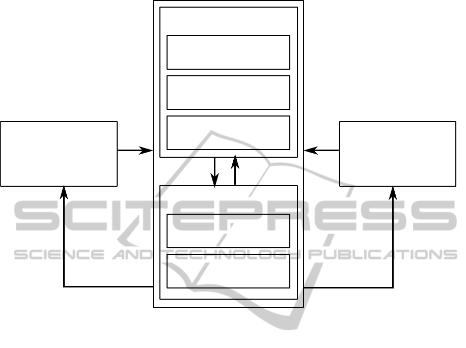
Assessment
Framework
Propagation
Method(s)
Result
Representation
Artifact: UQ System
Taxonomy
Test-Scenarios
Evaluation
Assess
Refine
Environment
Users of the
SESA-Lab
Knowledge Base
Literature
Research
Refine
Requirement
Analysis
Additions to the
Knowledge Base
Figure 2: Design process for the uncertainty quantification system analogous to the framework proposed by (Hevner et al.,
2004).
7 EXPECTED OUTCOME
The expected outcome of the presented PhD project
is a coupling between the simulation platforms
eMEGAsim and mosaik with quantifiable accuracy.
This will contribute to the development of the SESA-
Lab, a setup for software/hardware as well as steady-
state/dynamic Smart Grid co-simulation. The cou-
pling ensures accuracy by reducing temporal and
data value uncertainty through means of latency han-
dling, dynamic scheduling, and data transformation.
The remaining uncertainty is quantified via a flexible
UQ system that provides the user with standardized
means of interaction and readily evaluated propaga-
tion methods.
ACKNOWLEDGEMENT
The author would like to thank Prof. Sebastian Lehn-
hoff for valuable discussions, proofreading, and gen-
eral supervision of the PhD project. Further thank
goes to the SEE PhD program of the University of
Oldenburg for the possibility of pursuing the PhD.
REFERENCES
Adams, B. M., Ebeida, M. S., Eldred, M. S., Jakeman,
J. D., Swiler, L. P., Bohnhoff, W. J., Dalbey, K. R.,
Eddy, J. P., Hu, K. T., Vigil, D. M., Bauman, L. E.,
and Hough, P. D. (2014). Dakota, A Multilevel Paral-
lel Object-Oriented Framework for Design Optimiza-
tion, Parameter Estimation, Uncertainty Quantifica-
tion, and Sensitivity Analysis. Sandia National Lab-
oratories, P.O. Box 5800, Albuquerque, New Mexico
87185, 5.4 edition.
Avi
ˇ
zienis, A., Laprie, J.-C., Randell, B., and Landwehr, C.
(2004). Basic concepts and taxonomy of dependable
and secure computing. IEEE Transactions on Depend-
able and Secure Computing.
Borkowska, B. (1974). Probabilistic load flow. IEEE Trans-
actions on Power Apparatus and Systems.
de Jong, E., de Graaff, R., Vaessen, P., Crolla, P., Roscoe,
A., Lehfuß, F., Lauss, G., Kotsampopoulos, P., and
Gafaro, F. (2011). European white book on real-time
powerhardware-in-the-loop testing. Technical report.
Giunta, A. A., Wojtkiewicz Jr., S. F., and Eldred, M. S.
UncertaintyQuantificationinSmartGridCo-simulationAcrossHeterogeneousModelDomains
21

(2003). Overview of modern design of experiments
methods for computational simulations. In 41st
Aerospace Sciences Meeting and Exhibit.
Hevner, A. R., March, S. T., Park, J., and Ram, S. (2004).
Design science in information systems research. MIS
Quarterly.
Hiskens, I. A. and Alseddiqu, J. (2006). Sensitivity, approx-
imation, and uncertainty in power system dynamics.
IEEE Transactions on Power Systems.
Lechtenberg, M., G
¨
orner, K., G
¨
otze, J., and Rehtanz, C.
(2012). Estimation of oscillation parameters for power
grids. In IEEE Asia Pacific Conference on Circuits
and Systems.
Li, Y. and Zio, E. (2012). Uncertainty analysis of the ad-
equacy assessment model of a distributed generation
system. Renewable Energy.
Lin, G., Elizondo, M., Lu, S., and Wan, X. (2014). Uncer-
tainty quantification in dynamic simulations of large-
scale power system models using the high-order prob-
abilistic collocation method on sparse grids. Interna-
tional Journal of Uncertainty Quantification.
Lin, H., Sambamoorthy, S., Shukla, S., Thorp, J., and Mili,
L. (2011). Power system and communication network
co-simulation for smart grid applications. In Innova-
tive Smart Grid Technologies.
Makarov, Y. V., Huang, Z., Etingov, P. V., Ma, J., Gut-
tromson, R. T., Subbarao, K., and Chakrabarti, B. B.
(2010). Incorporating Wind Generation and Load
Forecast Uncertainties into Power Grid Operations.
Pacific Northwest National Laboratory.
Rohjans, S., Lehnhoff, S., Sch
¨
utte, S., and Scherfke, S.
(2013). mosaik – a modular platform for the eval-
uation of agent-based smart grid control. In 4th
IEEE/PES Innovative Smart Grid Technologies Eu-
rope.
Rosson, M. B. and Carroll, J. M. (2002). Scenario-based de-
sign. In The Human-Computer Interaction Handbook:
Fundamentals, Evolving Technologies and Emerging
Applications. Lawrence Erlbaum Associates.
Shariatinasab, R., Akbari, M., and Rahmani, B. (2012). Ap-
plication of wavelet analysis in power systems. In Ad-
vances in Wavelet Theory and Their Applications in
Engineering, Physics and Technology. InTech.
Wehenkel, L. (1997). Machine learning approaches to
power-system security assessment. IEEE Expert.
Zimmerman, R. D., Murillo-S
´
anchez, C. E., and Thomas,
R. J. (2011). Matpower: Steady-state operations, plan-
ning, and analysis tools for power systems research
and education. IEEE Transactions on Power Systems.
Zio, E. and Aven, T. (2011). Uncertainties in smart grids
behavior and modeling: What are the risks and vul-
nerabilities? how to analyze them? Energy Policy.
SIMULTECH2014-DoctoralConsortium
22
